
Chapter 266: Zigbee Implementation on ESP32-H2
Chapter Objectives
By the end of this chapter, you will be able to:
- Understand the fundamental concepts of Zigbee and the IEEE 802.15.4 standard.
- Describe the different Zigbee device roles and network topologies.
- Configure an ESP-IDF project for Zigbee development on an ESP32-H2.
- Implement a functional Zigbee end device, such as a simple on/off light.
- Understand the commissioning process to join a Zigbee device to a network.
- Recognize which ESP32 variants support Zigbee and why.
- Troubleshoot common issues in Zigbee development.
Introduction
Welcome to a fascinating area of IoT: low-power mesh networking. While Wi-Fi and Bluetooth are excellent for many applications, they are not always the ideal solution for large-scale, low-power device networks like those found in smart homes or industrial automation. This is where protocols like Zigbee shine.
Zigbee is a mature, robust, and secure wireless communication protocol built on the IEEE 802.15.4 standard. It is specifically designed for low-data-rate, low-power applications, enabling devices to form self-healing mesh networks and operate for years on a single battery. With the introduction of the ESP32-H2 and ESP32-C6, which feature a dedicated 802.15.4 radio, Espressif has brought this powerful technology into its ecosystem. This chapter will guide you through the theory and practice of building your first Zigbee device with the ESP32-H2 and ESP-IDF.
Theory
What is IEEE 802.15.4?
At the very foundation of Zigbee is the IEEE 802.15.4 standard. This standard defines the Physical Layer (PHY) and the Media Access Control (MAC) layer for low-rate wireless personal area networks (LR-WPANs). Think of it as the equivalent of the Ethernet standard for wired networks or 802.11 for Wi-Fi; it provides the basic rules for sending and receiving data packets over the air but doesn’t define how networks are formed or how applications should behave.
Key features of IEEE 802.15.4 include:
- Operating Frequencies: It primarily uses the unlicensed 2.4 GHz ISM band, the same band used by Wi-Fi and Bluetooth, but it can also operate in sub-gigahertz bands in some regions.
- Low Power Consumption: The standard is designed from the ground up for minimal power usage, allowing for long battery life.
- Low Data Rate: It supports data rates up to 250 kbps, which is more than sufficient for control and sensor data but far less than Wi-Fi.
The Zigbee Stack
Zigbee builds on top of the IEEE 802.15.4 standard by adding the upper layers required for creating scalable, interoperable, and self-healing mesh networks. These layers handle everything from network formation and security to application-level communication.
graph TD
    subgraph Zigbee Stack
        direction TB
        ZCL["<b>Zigbee Cluster Library (ZCL)</b><br><i>Defines standard device functions<br>(e.g., On/Off, Level Control)</i>"]
        AF["<b>Application Framework (AF)</b><br>Manages endpoints & clusters"]
        APS["<b>Application Support Sublayer (APS)</b><br>Handles message fragmentation & security"]
        NWK["<b>Network Layer (NWK)</b><br>Manages network formation, addressing & routing"]
    end

    subgraph IEEE 802.15.4
        direction TB
        MAC[<b>MAC Layer</b><br>Media Access Control]
        PHY[<b>PHY Layer</b><br>Physical Radio Layer - 2.4 GHz]
    end

    ZCL --> AF
    AF --> APS
    APS --> NWK
    NWK --> MAC
    MAC --> PHY

    classDef zigbee fill:#DBEAFE,stroke:#2563EB,stroke-width:1px,color:#1E40AF
    classDef ieee fill:#D1FAE5,stroke:#059669,stroke-width:2px,color:#065F46
    class ZCL,AF,APS,NWK zigbee
    class MAC,PHY ieee
- Network Layer (NWK): Responsible for network formation, addressing, and routing. It’s the “brains” of the mesh network, figuring out the best path for a message to travel from one node to another.
- Application Support Sublayer (APS): Acts as a bridge between the network layer and the application. It handles message fragmentation, reassembly, and enforces security policies.
- Application Framework (AF): Provides a standardized environment for applications to run. It defines endpoints (like a port in TCP/IP) and clusters, which group related functionality.
- Zigbee Cluster Library (ZCL): This is the heart of Zigbee interoperability. The ZCL defines a standard set of clusters, which are collections of commands and attributes for a specific function. For example, the “On/Off” cluster has commands like “On,” “Off,” and “Toggle,” and an attribute to report the current on/off state. By using these standard clusters, a light switch from one manufacturer can reliably control a light bulb from another.
Zigbee Network Topologies and Device Roles
Zigbee supports several network topologies, but its greatest strength is its mesh topology.
- Star: All devices communicate directly with a central controller. Simple, but has a single point of failure.
- Tree: A hierarchical structure where messages are routed up and down the tree. More robust than a star network.
- Mesh: The most powerful topology. Devices can communicate directly with their neighbors, and messages can be relayed through multiple nodes to reach their destination. If one path fails, the network can automatically “heal” by finding an alternative route.
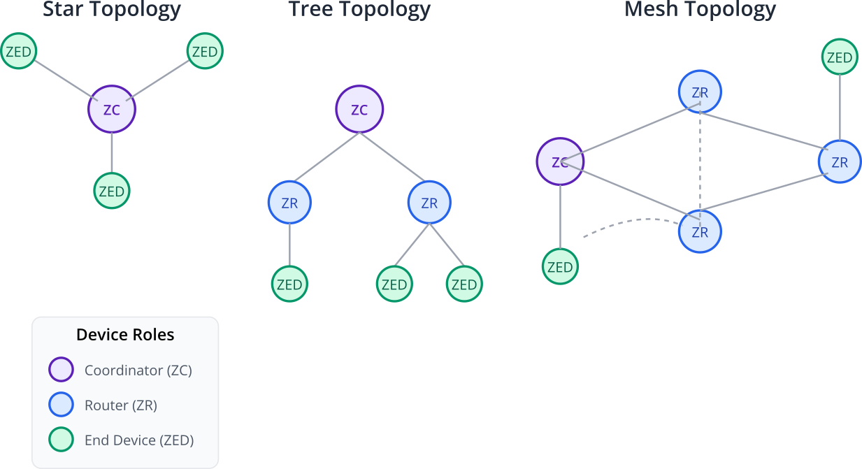
Within a Zigbee network, devices can have one of three roles:
- Coordinator (ZC): There is exactly one Coordinator in every Zigbee network. It is responsible for starting the network, selecting the radio channel, and managing security. It acts as the root of the network and often serves as a gateway to other networks (like the internet).
- Router (ZR): A Router is a full-function device that can route traffic for other nodes, extending the range and reliability of the network. It can also run applications (e.g., a smart light bulb that also acts as a router). Routers must be mains-powered as they need to be always on to participate in routing.
- End Device (ZED): A Zigbee End Device is a simplified device that does not route traffic. Its primary goal is to perform a specific function (e.g., a door sensor, a simple switch) and sleep as much as possible to conserve power. ZEDs are often battery-powered and communicate only with their parent Router or the Coordinator.
Practical Example: Building a Zigbee On/Off Light
Let’s apply this theory by building a simple Zigbee On/Off Light using an ESP32-H2 development board. This device will join a Zigbee network and respond to standard “On,” “Off,” and “Toggle” commands from a Zigbee coordinator (like a commercial hub or another ESP32-H2 programmed as a coordinator).
1. Project Setup in VS Code
We will use one of the official ESP-IDF examples as a starting point. The light example is perfect for our needs.
- Open VS Code with the Espressif IDF extension installed.
- Press
F1to open the command palette and typeESP-IDF: Show Examples Projects, then press Enter. - Select your current ESP-IDF version.
- In the examples list, find and select
zigbee/light. - A new window will appear. Click the
Create project using example lightbutton and choose a location on your computer to save the project.
2. Hardware Setup
You will need:
- An ESP32-H2 development board (e.g., the ESP32-H2-DevKitM-1).
- A USB cable for flashing and power.
- An LED and a current-limiting resistor (e.g., 330Ω) to connect to a GPIO pin, or you can use the onboard RGB LED if your dev kit has one. For this example, we’ll assume the onboard LED is on GPIO8.
3. Code Walkthrough
Open the main/esp_light_main.c file. The example code is already well-structured, but let’s break down the key components.
/* main/esp_light_main.c */

#include "esp_log.h"
#include "freertos/FreeRTOS.h"
#include "freertos/task.h"
#include "ha/esp_zigbee_ha_standard.h"
#include "esp_light.h"

// ... (other includes)

static const char *TAG = "ESP_ZIGBEE_LIGHT";

/********************* Define functions **************************/
// This structure holds information about the light bulb's state.
typedef struct light_bulb_device_params_s {
    esp_zb_ieee_addr_t ieee_addr;
    uint8_t  endpoint;
    uint16_t short_addr;
} light_bulb_device_params_t;

// This function is called when the light's state (on/off) needs to change.
static void esp_zb_buttons_handler(uint8_t button_evt)
{
    // In a real product, this would handle physical button presses on the device.
    // For this example, it's not used, but it shows how you would integrate local control.
}

// Main Zigbee stack event handler.
static void bdb_start_top_level_commissioning_cb(uint8_t mode_mask)
{
    // This function is called when the device needs to join a network.
    // It starts the commissioning process, making the device discoverable.
    ESP_ERROR_CHECK(esp_zb_bdb_start_top_level_commissioning(mode_mask));
}

void esp_zb_app_signal_handler(esp_zb_app_signal_t *signal_struct)
{
    uint32_t *p_sg_p       = signal_struct->p_app_signal;
    esp_err_t err_status = signal_struct->esp_err_status;
    esp_zb_app_signal_type_t sig_type = *p_sg_p;

    switch (sig_type) {
    case ESP_ZB_ZDO_SIGNAL_SKIP_STARTUP:
        ESP_LOGI(TAG, "Zigbee stack initialized");
        esp_zb_bdb_start_top_level_commissioning(ESP_ZB_BDB_MODE_INITIALIZATION);
        break;
    case ESP_ZB_BDB_SIGNAL_DEVICE_FIRST_START:
    case ESP_ZB_BDB_SIGNAL_DEVICE_REBOOT:
        if (err_status == ESP_OK) {
            ESP_LOGI(TAG, "Device started up in %s factory-new mode", esp_zb_bdb_is_factory_new() ? "" : "non");
            if (esp_zb_bdb_is_factory_new()) {
                ESP_LOGI(TAG, "Start network steering");
                esp_zb_bdb_start_top_level_commissioning(ESP_ZB_BDB_MODE_NETWORK_STEERING);
            } else {
                ESP_LOGI(TAG, "Device rebooted");
            }
        } else {
            ESP_LOGE(TAG, "Failed to initialize Zigbee stack");
        }
        break;
    case ESP_ZB_BDB_SIGNAL_STEERING_COMPLETE:
        if (err_status == ESP_OK) {
            esp_zb_ieee_addr_t extended_pan_id;
            esp_zb_get_extended_pan_id(extended_pan_id);
            ESP_LOGI(TAG, "Successfully joined network, extended_pan_id: %02x:%02x:%02x:%02x:%02x:%02x:%02x:%02x, pan_id: 0x%04hx, channel: %d",
                     extended_pan_id[7], extended_pan_id[6], extended_pan_id[5], extended_pan_id[4],
                     extended_pan_id[3], extended_pan_id[2], extended_pan_id[1], extended_pan_id[0],
                     esp_zb_get_pan_id(), esp_zb_get_current_channel());
        } else {
            ESP_LOGI(TAG, "Network steering was not successful (status: %d)", err_status);
            esp_zb_scheduler_alarm(bdb_start_top_level_commissioning_cb, ESP_ZB_BDB_MODE_NETWORK_STEERING, 1000);
        }
        break;
    default:
        ESP_LOGI(TAG, "ZDO signal: %d, status: %d", sig_type, err_status);
        break;
    }
}

// This task handles the main Zigbee processing loop.
static void esp_zb_task(void *pvParameters)
{
    // Initialize the Zigbee stack configuration
    esp_zb_cfg_t zb_nwk_cfg = ESP_ZB_DEFAULT_CONFIG();
    // Set the role to Router. It could also be an End Device.
    // Routers help build the mesh, End Devices are low-power.
    zb_nwk_cfg.esp_zb_role = ESP_ZB_DEVICE_TYPE_ROUTER;
    // Initialize the stack with the configuration
    esp_zb_init(&zb_nwk_cfg);

    // ** Define the Endpoint and Clusters for our Light Bulb **
    // A device can have multiple endpoints, each with different functions.
    // We have one endpoint for our light.
    esp_zb_ep_list_t *esp_zb_ep_list = esp_zb_ep_list_create();

    // The ZCL defines standard clusters. We use On/Off, Level Control, Identify, etc.
    // This makes our light compatible with other Zigbee devices.
    esp_zb_cluster_list_t *esp_zb_cluster_list = esp_zb_cluster_list_create();

    // Create the Basic cluster (mandatory)
    esp_zb_attribute_list_t *esp_zb_basic_cluster = esp_zb_basic_cluster_create(NULL);
    esp_zb_cluster_list_add_cluster(esp_zb_cluster_list, esp_zb_basic_cluster, ESP_ZB_ZCL_CLUSTER_SERVER_ROLE);

    // Create the Identify cluster (for finding the device)
    esp_zb_attribute_list_t *esp_zb_identify_cluster = esp_zb_identify_cluster_create(NULL);
    esp_zb_cluster_list_add_cluster(esp_zb_cluster_list, esp_zb_identify_cluster, ESP_ZB_ZCL_CLUSTER_SERVER_ROLE);

    // ** Create the On/Off cluster - This is the key part for our light **
    esp_zb_on_off_cluster_cfg_t on_off_cfg;
    on_off_cfg.on_off = ESP_ZB_ZCL_ON_OFF_ON_OFF_DEFAULT_VALUE; // Default to off
    esp_zb_attribute_list_t *esp_zb_on_off_cluster = esp_zb_on_off_cluster_create(&on_off_cfg);
    esp_zb_cluster_list_add_cluster(esp_zb_cluster_list, esp_zb_on_off_cluster, ESP_ZB_ZCL_CLUSTER_SERVER_ROLE);

    // Add the cluster list to the endpoint list
    esp_zb_ep_list_add_ep(esp_zb_ep_list, esp_zb_cluster_list, HA_ESP_LIGHT_ENDPOINT, ESP_ZB_AF_HA_PROFILE_ID, ESP_ZB_HA_ON_OFF_LIGHT_DEVICE_ID);

    // Register the endpoint list with the Zigbee stack
    esp_zb_device_register(esp_zb_ep_list);

    // Set the Zigbee event handler function
    esp_zb_set_primary_network_channel_set(ESP_ZB_PRIMARY_CHANNEL_MASK);
    ESP_ERROR_CHECK(esp_zb_start(false));

    // This is the main loop for the Zigbee task
    esp_zb_main_loop_iteration();
}

// This function gets called whenever a Zigbee attribute is changed by an external command.
// For example, when the coordinator sends an "On" command.
static esp_err_t zb_attribute_handler(const esp_zb_zcl_set_attr_value_message_t *message)
{
    esp_err_t ret = ESP_OK;
    ESP_RETURN_ON_FALSE(message, ESP_FAIL, TAG, "Empty message");
    ESP_RETURN_ON_FALSE(message->info.status == ESP_ZB_ZCL_STATUS_SUCCESS, ESP_ERR_INVALID_ARG, TAG, "Received message with error status");
    ESP_LOGI(TAG, "Received message: endpoint(0x%x), cluster(0x%x), attribute(0x%x), data size(%d)",
             message->info.dst_endpoint, message->info.cluster, message->info.attr_id, message->info.data.size);

    // Check if the message is for the On/Off cluster
    if (message->info.cluster == ESP_ZB_ZCL_CLUSTER_ID_ON_OFF) {
        // Check if the attribute is the OnOff attribute
        if (message->info.attr_id == ESP_ZB_ZCL_ATTR_ON_OFF_ON_OFF_ID) {
            // Get the new value (0 for Off, 1 for On)
            uint8_t value = *(uint8_t *)message->info.data.value;
            ESP_LOGI(TAG, "On/Off attribute changed to %s", value ? "ON" : "OFF");

            // *** This is where you control the hardware! ***
            light_driver_set_power(value);
        }
    }
    return ret;
}

void app_main(void)
{
    // Initialize standard ESP32 components
    esp_zb_platform_config_t config = {
        .radio_config = ESP_ZB_DEFAULT_RADIO_CONFIG(),
        .host_config = ESP_ZB_DEFAULT_HOST_CONFIG(),
    };
    ESP_ERROR_CHECK(esp_zb_platform_init(&config));

    // Register our custom attribute handler
    ESP_ERROR_CHECK(esp_zb_add_usr_cb(zb_attribute_handler));

    // Create and start the main Zigbee task
    xTaskCreate(esp_zb_task, "Zigbee_main", 4096, NULL, 5, NULL);
}
Tip: The
light_driver_set_power()function is an abstraction provided incomponents/esp_light/light_driver.c. It handles the GPIO operations. By default, it might be configured for a specific dev board. You may need to modifylight_driver.cor usemenuconfigto change theCONFIG_ZIGBEE_LIGHT_GPIOto match your hardware setup.
4. Configuration and Building
- Set the Target: In the VS Code status bar, click on the current target (e.g.,
esp32) and change it to your specific variant,esp32h2. - Run
menuconfig: Open a new ESP-IDF terminal in VS Code (Ctrl+orCmd+idf.py menuconfig. - Verify Configuration:
- Navigate to
Component config—>Zigbee. - Ensure
Zigbee roleis set toRouterorEnd Device. For a light bulb,Routeris common if it’s mains-powered, as this strengthens the mesh. - Under
Component config—>Zigbee—>Light Example Configuration, you can set theGPIO number for lightif you don’t want to use the default.
- Navigate to
- Save and Exit
menuconfig. - Build the Project: In the ESP-IDF terminal, run
idf.py build.
5. Flashing and Running
- Connect your ESP32-H2 board to your computer.
- Flash the code: In the ESP-IDF terminal, run the command:
idf.py -p /dev/ttyUSB0 flash(replace/dev/ttyUSB0with your board’s serial port, which might beCOMxon Windows). - Monitor the Output: Run
idf.py -p /dev/ttyUSB0 monitor. You should see logs from the device as it boots up.
flowchart TD
    A[Start: Device Powers On] --> B{ESP-IDF Zigbee<br>Stack Initialized?};
    B -- Yes --> C{Device is Factory New?};
    B -- No --> X[Error: Failed to<br>Initialize Stack];

    C -- Yes --> D["<b>Network Steering</b><br>Start searching for an<br>open Zigbee network to join"];
    C -- No --> E["<b>Rejoin Process</b><br>Attempt to reconnect to the<br>previously known network"];

    D --> F{Network Found?};
    F -- Yes --> G[Join Network &<br>Get Address];
    F -- No --> H["Steering Failed<br>(Timeout)"];

    E --> G;

    H --> I{Retry Steering?};
    I -- Yes --> D;
    I -- No --> J[Enter Low Power State<br>or Wait for User Input];

    G --> K[Commissioning Complete!<br><b>Successfully Joined Network</b>];

    %% Styling
    classDef start fill:#EDE9FE,stroke:#5B21B6,stroke-width:2px,color:#5B21B6;
    classDef process fill:#DBEAFE,stroke:#2563EB,stroke-width:1px,color:#1E40AF;
    classDef decision fill:#FEF3C7,stroke:#D97706,stroke-width:1px,color:#92400E;
    classDef success fill:#D1FAE5,stroke:#059669,stroke-width:2px,color:#065F46;
    classDef failure fill:#FEE2E2,stroke:#DC2626,stroke-width:1px,color:#991B1B;

    class A,E,D start;
    class B,C,F,I decision;
    class G process;
    class K success;
    class X,H,J failure;
When it starts, it will be in “factory-new” mode and will begin “network steering.” This means it is actively trying to find and join a Zigbee network.
6. Commissioning and Testing
To test your light, you need a Zigbee Coordinator. This can be:
- A commercial hub: Amazon Echo (4th gen or newer), Philips Hue Bridge, SmartThings Hub, etc. Put the hub into pairing mode (e.g., “Alexa, discover devices”). The ESP32-H2 light should be found and added. You can then control it via the Alexa app or by voice.
- Another ESP32-H2/C6: You can flash the
zigbee/coordinatorexample onto a second board. Once the coordinator is running, it will form a network, and your light device will automatically join it. You can then use the coordinator’s command-line interface to send on/off commands.
Once the light successfully joins the network, the monitor output will show:
I (xxxx) ESP_ZIGBEE_LIGHT: Successfully joined network, …
Now, when you use your coordinator (e.g., the Alexa app) to turn the light on or off, you will see the corresponding log message in the monitor, and the physical LED on your board will change state!
I (xxxx) ESP_ZIGBEE_LIGHT: On/Off attribute changed to ON
Variant Notes
- ESP32-H2 & ESP32-C6: These are the primary SoCs from Espressif that support Zigbee. They have a built-in IEEE 802.15.4 radio, which is a hardware prerequisite for Zigbee communication. The ESP-IDF Zigbee stack is fully supported on these chips.
- ESP32, ESP32-S2, ESP32-S3, ESP32-C3: These variants do not have an 802.15.4 radio. Therefore, they cannot run the Zigbee protocol natively. It is technically possible to create a Zigbee gateway by connecting an external 802.15.4 radio module (via SPI or UART) to one of these SoCs, but they cannot act as standalone Zigbee devices.
Common Mistakes & Troubleshooting Tips
- Mistake: Device fails to join the network.
- Troubleshooting:
- Ensure your Zigbee Coordinator/Hub is in pairing mode and is physically close to the ESP32-H2 during the first join attempt.
- Check the monitor logs. If it says “Network steering was not successful,” it means it couldn’t find a network to join. Try factory resetting the device by erasing the flash (
idf.py erase_flash) and re-flashing. - Verify that both the coordinator and the end device are not on conflicting Zigbee channels. While steering should handle this, interference from 2.4GHz Wi-Fi can be an issue.
- Troubleshooting:
- Mistake: The device joins, but doesn’t respond to commands.
- Troubleshooting:
- Double-check that your
zb_attribute_handlerfunction is correctly registered withesp_zb_add_usr_cb(). - Ensure the logic inside the handler is correct. Are you checking for the right cluster ID (
ESP_ZB_ZCL_CLUSTER_ID_ON_OFF) and attribute ID (ESP_ZB_ZCL_ATTR_ON_OFF_ON_OFF_ID)? - Verify your hardware control function (
light_driver_set_power) is pointing to the correct GPIO and is functioning as expected.
- Double-check that your
- Troubleshooting:
- Mistake: Build fails with errors related to Zigbee functions.
- Troubleshooting:
- Make sure you have selected the correct target board (ESP32-H2) in VS Code. Building a Zigbee project for an incompatible target like the ESP32-S3 will result in errors.
- Ensure that the Zigbee component is enabled in
menuconfig. If you started from a blank project, you might need to enable it manually underComponent config.
- Troubleshooting:
- Mistake: The device seems to crash or reboot randomly.
- Troubleshooting:
- Zigbee is a complex stack and requires a fair amount of RAM and task stack space. In
app_main, ensure the stack size foresp_zb_taskis sufficient. The default of 4096 bytes is usually fine, but if you add more complex logic, you might need to increase it. - Check for stack overflows using the ESP-IDF’s built-in tools.
- Zigbee is a complex stack and requires a fair amount of RAM and task stack space. In
- Troubleshooting:
Exercises
- Dimmable Light: Modify the project to be a “Dimmable Light.” This involves adding the Level Control cluster (
esp_zb_level_control_cluster_create) to your endpoint. In thezb_attribute_handler, add logic to handle attribute changes for theESP_ZB_ZCL_CLUSTER_ID_LEVEL_CONTROLcluster. Use the received level value (0-254) to control the brightness of the LED using the LEDC (PWM) peripheral. - Zigbee Switch: Create a new project based on the
zigbee/light_switchexample. Configure it to control the Zigbee light you built in this chapter. This will require you to understand how to send ZCL commands (likeesp_zb_zcl_on_off_cmd_req) from the switch to the light’s address. - Battery-Powered Sensor: Modify the On/Off light project to be a battery-powered end device.
- In
menuconfig, change theZigbee roletoEnd Device. - Remove the On/Off cluster and add the Temperature Measurement cluster.
- Write a task that periodically reads a (real or simulated) temperature sensor and updates the temperature attribute value using
esp_zb_zcl_set_attribute_val(). Because it’s an end device, it can now enter low-power sleep modes between transmissions.
- In
Summary
- Zigbee is a low-power, mesh networking protocol based on the IEEE 802.15.4 standard, ideal for smart home and industrial applications.
- The ESP32-H2 and ESP32-C6 are the Espressif SoCs with the required 802.15.4 radio hardware to run Zigbee natively.
- Zigbee networks consist of a Coordinator, Routers, and End Devices.
- Interoperability in Zigbee is achieved through the Zigbee Cluster Library (ZCL), which defines standard commands and attributes for device functions (e.g., On/Off, Level Control).
- Developing a Zigbee application in ESP-IDF involves initializing the stack, defining device endpoints and clusters, and handling events and attribute changes in callback functions.
- Commissioning is the process by which a new device securely joins a Zigbee network.
Further Reading
- Espressif Zigbee Guide: The official documentation is the most important resource.
- Zigbee Alliance (now Connectivity Standards Alliance): For deep technical specifications on Zigbee 3.0 and the ZCL.
- Example Projects: Explore other examples in the
zigbeedirectory of ESP-IDF for more complex applications like coordinators, custom clusters, and more.
