
Chapter 1: What is an Embedded System?
Chapter Objectives
Upon completing this chapter, you will be able to:
- Define what constitutes an embedded system and differentiate it from a general-purpose computer.
- Identify the core characteristics of embedded systems, including resource constraints, reliability, and dedicated functionality.
- Understand the fundamental relationship between hardware and software in an embedded context.
- Recognize real-world examples of embedded systems and appreciate their role in modern technology.
- Explain why a powerful single-board computer like the Raspberry Pi 5 can serve as an effective platform for learning embedded principles.
- Perform basic resource monitoring on a Linux system to gain practical insight into system constraints.
Introduction
Welcome to the fascinating world of embedded systems. If you’ve ever used a microwave, a digital watch, a modern car, or a smart thermostat, you have interacted with an embedded system. They are the silent workhorses of our technological world—specialized computing systems designed to perform a dedicated function, often in real-time and with significant constraints on resources like power, memory, and processing capability. Unlike your desktop PC or laptop, which is a general-purpose machine designed to run a vast array of different applications, an embedded system is an expert, meticulously engineered for one primary purpose. From the anti-lock braking system in a car to the flight controller in a drone, these systems are everywhere, forming the invisible fabric of modern life.
This chapter serves as your formal introduction to this critical field. We will move beyond simple definitions to build a deep, foundational understanding of what makes a system “embedded.” We will explore the unique challenges and design considerations that define this engineering discipline, such as the tight coupling of hardware and software and the paramount importance of reliability. Understanding these core principles is the first and most crucial step in your journey. While professional embedded systems are often built on highly specialized hardware, we will use the Raspberry Pi 5 as our learning platform. Its combination of accessible hardware I/O (Input/Output) and the power to run a full-featured Linux operating system makes it an ideal environment to bridge the gap between high-level software and the underlying hardware, allowing us to explore embedded concepts in a practical, hands-on manner.
Technical Background
The Core Definition: Beyond General-Purpose Computing
At its heart, an embedded system is a combination of computer hardware and software designed to perform a specific, dedicated task. This definition, while accurate, only scratches the surface. The true essence of an embedded system lies not just in what it is, but in the constraints and design principles that shape it. The journey from a general-purpose computer to a specialized embedded device is one of deliberate engineering trade-offs, where every component and line of code is scrutinized for efficiency, cost, and reliability.
Characteristic 1: Dedicated Function
The most defining characteristic of an embedded system is its dedicated function. Consider the engine control unit (ECU) in a modern automobile. Its job is singular and critical: to manage the engine’s performance by monitoring sensors and controlling actuators to optimize fuel injection, ignition timing, and emissions. It does not run web browsers, word processors, or video games. This specialization is its greatest strength. By focusing on a narrow set of tasks, engineers can optimize the system to a degree that is impossible in a general-purpose computer. The hardware can be tailored to the exact requirements of the task, eliminating costly and power-hungry components that are not needed. The software can be stripped down to its bare essentials, reducing complexity, minimizing the potential for bugs, and ensuring that critical tasks can be executed predictably and on time.
Characteristic 2: Resource Constraints
This leads directly to the second core characteristic: resource constraints. Embedded systems are almost always designed to operate within a strict budget of size, cost, and power consumption. The processor in your smart thermostat, for example, is far less powerful than the one in your smartphone. It has just enough processing power to read temperature sensors, execute its control algorithm, and update its display—and no more. This is a deliberate design choice. A less powerful processor is cheaper, smaller, and, most importantly, consumes significantly less electrical power. In a battery-operated device or a system that will be manufactured in the millions, these savings are paramount. Memory, both RAM for active computation and non-volatile storage (like Flash memory) for the program code, is similarly constrained. An embedded developer must be perpetually conscious of their memory footprint, carefully managing every byte to ensure the system can operate within its hardware limits.
Characteristic 3: Real-Time Operation
The concept of real-time operation is another critical pillar of embedded systems, though it is often misunderstood. “Real-time” does not necessarily mean “very fast.” Rather, it means “predictably on time.” A real-time system is one that must guarantee a response to an event within a strict, predetermined time deadline. Missing a deadline is considered a system failure. Let’s return to the car’s anti-lock braking system (ABS). When a sensor detects that a wheel is about to lock up, the ABS controller must respond by modulating the brake pressure within milliseconds. A delay of even a fraction of a second could be catastrophic. This is a hard real-time system, where failure to meet a deadline has severe consequences.
%%{ init: { 'theme': 'base', 'themeVariables': { 'fontFamily': 'Open Sans' } } }%%
graph LR
    subgraph "Hard Real-Time (e.g., Automotive ABS)"
        direction LR
        A1(Event: <br>Wheel Lock Detected) --> B1{Process Data};
        B1 --> C1(Meet Deadline?);
        C1 -- Yes --> D1[Modulate Brakes: <br>SUCCESS];
        C1 -- No --> E1[Deadline Missed: <br>CATASTROPHIC FAILURE];
    end

    subgraph "Soft Real-Time (e.g., Infotainment Media Player)"
        direction LR
        A2(Event: <br>'Next Track' Button Pressed) --> B2{Process Request};
        B2 --> C2(Meet Deadline?);
        C2 -- Yes --> D2[Play Next Track: <br>SUCCESS];
        C2 -- No --> E2["Deadline Missed: <br>DEGRADED PERFORMANCE <br><i>(Annoying lag)</i>"];
    end

    %% Styling
    classDef primary fill:#1e3a8a,stroke:#1e3a8a,stroke-width:2px,color:#ffffff;
    classDef success fill:#10b981,stroke:#10b981,stroke-width:2px,color:#ffffff;
    classDef decision fill:#f59e0b,stroke:#f59e0b,stroke-width:1px,color:#ffffff;
    classDef process fill:#0d9488,stroke:#0d9488,stroke-width:1px,color:#ffffff;
    classDef failure fill:#ef4444,stroke:#ef4444,stroke-width:1px,color:#ffffff;
    classDef warning fill:#eab308,stroke:#eab308,stroke-width:1px,color:#1f2937;

    class A1,A2 primary;
    class B1,B2 process;
    class C1,C2 decision;
    class D1,D2 success;
    class E1 failure;
    class E2 warning;
In contrast, a soft real-time system can tolerate occasional missed deadlines, though performance will degrade. For example, the media player in your car’s infotainment system should ideally respond instantly when you press the “next track” button. If it occasionally takes an extra half-second to respond, it’s annoying but not dangerous. The system’s overall utility is diminished, but it hasn’t failed in a critical sense. The design of real-time systems involves a deep interplay between the operating system’s scheduler, interrupt handling, and careful software design to ensure that tasks are prioritized and executed in a deterministic manner. The Linux kernel, while not a hard real-time operating system by default, can be configured with extensions like PREEMPT_RT to provide the deterministic behavior required for many real-time applications.
Characteristic 4: Unwavering Reliability
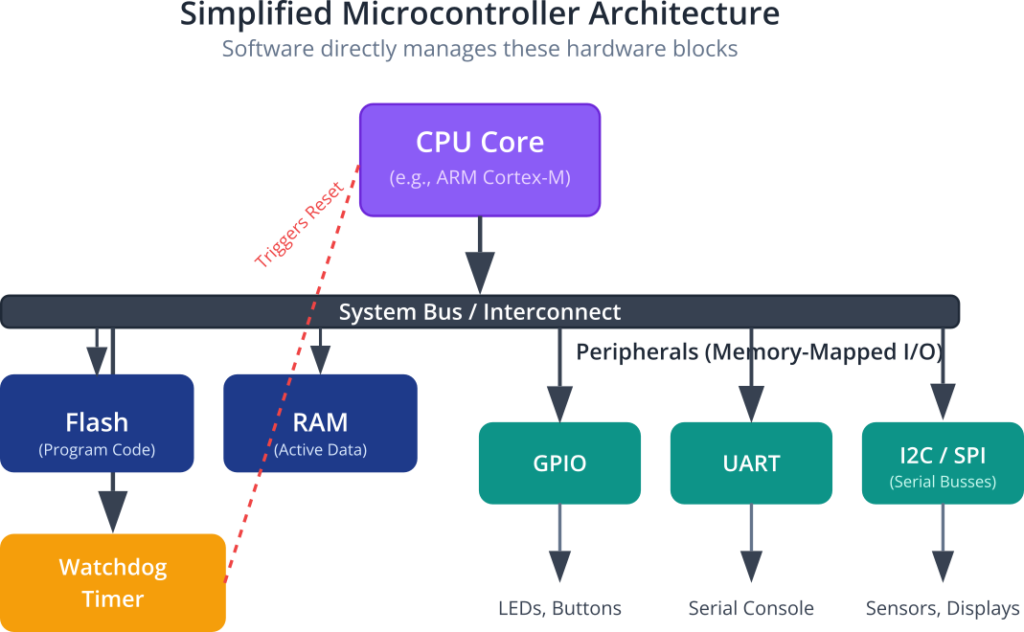
This deterministic behavior is intrinsically linked to reliability and stability. Embedded systems are expected to operate flawlessly for years without human intervention. The software controlling a satellite, a medical pacemaker, or a power grid controller cannot simply be rebooted if it crashes. This demands a level of robustness far beyond that of desktop software. The code must be rigorously tested, with sophisticated error handling to manage unexpected sensor readings, hardware faults, or communication dropouts. Often, these systems incorporate a watchdog timer, which is a simple hardware counter that is periodically reset by the software. If the software hangs or crashes, it will fail to reset the timer. When the timer expires, it triggers a hardware reset of the entire system, forcing it back into a known good state. This is a fundamental fail-safe mechanism in countless embedded designs.
The Hardware-Software Symbiosis
Finally, the tight coupling of hardware and software is a defining feature of the embedded world. An embedded software engineer must have a much deeper understanding of the underlying hardware than a typical application developer. You cannot write a device driver without intimately knowing the registers, memory maps, and communication protocols of the hardware component you are trying to control. This is where documents like datasheets and technical reference manuals become a developer’s most important tools. The software is not an abstract layer running on generic hardware; it is a meticulously crafted set of instructions designed to manipulate specific electronic components. This interaction happens at a very low level, often involving direct manipulation of memory-mapped hardware registers. For example, to turn on an LED connected to a specific pin on a microcontroller, the software doesn’t call a high-level function like turnOnLed(). Instead, it writes a specific bit pattern to a specific memory address that corresponds to the hardware register controlling that pin.
Bridging Theory and Practice with the Raspberry Pi 5
The Raspberry Pi 5, while vastly more powerful than a typical microcontroller, provides an excellent platform for learning these concepts. It runs Linux, a powerful operating system that typically abstracts away the hardware. However, it also exposes its hardware peripherals, like the General-Purpose Input/Output (GPIO) pins, through interfaces that allow us to peel back those layers of abstraction. We can write a Python script that feels like a high-level application, but which ultimately manipulates the same hardware control registers as a low-level C program on a simple microcontroller. This allows us to start with familiar, high-level concepts and progressively dig deeper into the hardware-software interface, which is the very heart of embedded systems engineering. By monitoring its resource usage, interacting with its I/O, and understanding how the operating system manages its hardware, we can use the Raspberry Pi to gain tangible, practical experience with the core principles that govern all embedded systems, from the simplest smart lightbulb to the most complex interplanetary rover.
Practical Examples
Theory provides the foundation, but true understanding is forged through practice. In this section, we will use the Raspberry Pi 5 to move from abstract concepts to concrete, hands-on examples. These exercises are designed to illustrate the core characteristics of an embedded system in a tangible way.
Example 1: The “Embedded Hello, World” – Blinking an LED
The quintessential first step in embedded development is not printing “Hello, World!” to a screen, but making something happen in the physical world. Blinking an LED is the classic example. It demonstrates direct hardware control, the most fundamental aspect of an embedded system.
Hardware Integration
You will need the following components:
- A Raspberry Pi 5 with Raspberry Pi OS installed and configured.
- A breadboard.
- One standard LED (any color).
- One 330Ω resistor.
- Jumper wires (male-to-female).
Wiring Instructions:
- Safety First: Ensure your Raspberry Pi 5 is powered off and disconnected from the power supply before making any connections.
- Connect one end of a jumper wire to a Ground pin on the Raspberry Pi. Pin 6 is a convenient choice. Connect the other end to the blue (negative) rail on your breadboard.
- Connect another jumper wire from GPIO pin 17 (physical pin 11) on the Raspberry Pi to a row on the breadboard.
- Place the 330Ω resistor on the breadboard, with one leg in the same row as the wire from GPIO 17.
- Place the LED on the breadboard. Connect its longer leg (the anode, positive) to the other leg of the resistor.
- Connect the shorter leg of the LED (the cathode, negative) to the ground rail on the breadboard.

Warning: Always use a current-limiting resistor when connecting an LED to a GPIO pin. Connecting an LED directly can draw too much current from the pin, potentially damaging the Raspberry Pi permanently.
Code and Procedure
We will use Python and the gpiozero library, which provides a simple, high-level interface to the GPIO pins.
Power on your Raspberry Pi 5 and open a terminal window.
Create a new Python file named blinker.py:
nano blinker.pyEnter the following code into the file:
# Import the necessary libraries
from gpiozero import LED
from time import sleep

# Create an LED object connected to GPIO pin 17
# The library handles the low-level setup for us.
led = LED(17)

print("Starting LED blinker program. Press Ctrl+C to exit.")

try:
    # This is the main loop of our embedded program.
    # It will run forever until interrupted.
    while True:
        # Turn the LED on
        led.on()
        print("LED ON")
        # Wait for 1 second
        sleep(1)

        # Turn the LED off
        led.off()
        print("LED OFF")
        # Wait for 1 second
        sleep(1)

except KeyboardInterrupt:
    # This block runs when you press Ctrl+C
    print("\nProgram terminated. Cleaning up GPIO.")
    # The gpiozero library automatically handles cleanup,
    # but it's good practice to be explicit.
    led.close()
Save the file and exit the editor (Ctrl+X, then Y, then Enter).
Run the program from the terminal:
python3 blinker.pyExpected Output:
You should see the LED on your breadboard turn on for one second, then off for one second, repeating indefinitely. In the terminal, you will see the corresponding “LED ON” and “LED OFF” messages. This simple program perfectly encapsulates the dedicated-function nature of an embedded system. It does one thing—blink an LED—and does it reliably and continuously until it is stopped.
Example 2: Monitoring System Resources
A key aspect of embedded systems is operating within resource constraints. While the Raspberry Pi 5 is powerful, the principles of monitoring CPU and memory are universal. We will use standard Linux command-line tools to observe how our system behaves.
Procedure and Commands
- Monitoring with top:The top command provides a real-time, dynamic view of the processes running on your system. Open a terminal and run it:
topYou will see a constantly updating table. The top few lines provide a summary of the system’s state.%Cpu(s): This shows the CPU usage, broken down by categories likeus(user space),sy(system/kernel space), andid(idle). In a quiet system, the idle percentage will be very high.MiB Mem: This shows your total RAM, how much is free, and how much is used.
- Generating a Load:Now, let’s see how these numbers change when the system is doing work. Open a second terminal window (leaving top running in the first). In this new terminal, we will run a command to stress the CPU. The stress-ng tool is excellent for this, but a simple infinite loop in bash works too.
# This command creates an infinite loop that performs a calculation,# consuming CPU cycles on a single core.while true; do a=1; done - Observing the Change:Look back at your top window. You will see a dramatic change. The %Cpu(s) idle value (id) will drop significantly, and one of the cores will show close to 100% usage. You will also see the bash process near the top of the process list, consuming the CPU.
- Monitoring Memory with free:The free command gives a snapshot of memory usage. It’s less dynamic than top but very clear.
free -hThe-hflag makes the output “human-readable” (e.g., showing MB or GB).# Expected output will look something like this: total used free shared buff/cache available Mem: 7.8Gi 450Mi 6.8Gi 20Mi 550Mi 7.1Gi Swap: 100Mi 0B 100MiThis simple act of monitoring provides a practical feel for the finite nature of system resources. In a professional embedded project, engineers spend a great deal of time profiling their applications to ensure that CPU usage never unexpectedly spikes to 100% and that memory usage stays well within the available RAM, preventing crashes and instability.
Common Mistakes & Troubleshooting
As you begin your journey in embedded systems, you will inevitably encounter some common pitfalls. Recognizing them early is key to a smoother learning curve.
Exercises
These exercises are designed to build upon the practical examples and reinforce the core concepts of the chapter.
- Modified Blinker: The S.O.S. Signal
- Objective: Modify the
blinker.pyscript to flash the LED in the pattern of an S.O.S. signal (three short flashes, three long flashes, three short flashes). This exercise reinforces the concept of software controlling hardware timing to create a specific, functional pattern. - Guidance: A “short” flash could be 0.2 seconds, and a “long” flash could be 0.6 seconds. You will need to add appropriate
sleep()calls between theled.on()andled.off()calls. Think about the pauses needed between letters (e.g., 1 second) and between full S.O.S. sequences (e.g., 3 seconds). - Verification: Run the script and visually confirm that the LED flashes in the correct S.O.S. pattern.
- Objective: Modify the
- User Input to Hardware Output: The Push-Button LED
- Objective: Add a push button to your circuit that controls the LED. When the button is pressed, the LED should turn on. When it is released, the LED should turn off. This introduces the concept of hardware input triggering a software response.
- Hardware: You will need a tactile push button to add to your breadboard.
- Guidance: Connect one side of the button to a GPIO pin (e.g., GPIO 26) and the other side to Ground. Use the
gpiozerolibrary’sButtonclass. The code will look something like this:from gpiozero import Button; button = Button(26). You can then usebutton.wait_for_press()andbutton.wait_for_release()or check its state in a loop withif button.is_pressed:. - Verification: The LED should light up immediately when you press the button and turn off as soon as you release it.
- Basic Resource Profiling
- Objective: Write a simple Python script that performs a computationally intensive task (e.g., calculating a large number of prime numbers) and simultaneously monitor the system’s CPU and memory usage.
- Guidance: Create a Python script that runs a heavy calculation in a loop. While it’s running, use the
topandfree -hcommands in another terminal to observe the impact. Log the CPU usage and memory usage at the start of the script and after it has been running for one minute. - Expected Outcome: You should observe a significant increase in CPU usage for the Python process and a small but measurable increase in memory consumption. This exercise provides a practical demonstration of how software execution consumes finite system resources.
Summary
This chapter has introduced the foundational concepts of embedded systems. We have moved from a simple definition to a more nuanced understanding of the principles that guide embedded engineering.
- Dedicated Function: Embedded systems are specialized computers designed to perform a specific task or a small set of related tasks.
- Resource Constraints: They are engineered to operate within strict limits of processing power, memory, physical size, and power consumption.
- Reliability: Embedded systems must be highly reliable and stable, often operating for years without failure or human intervention. Watchdog timers are a common hardware mechanism to ensure robustness.
- Real-Time Operation: Many embedded systems are real-time systems, meaning they must respond to events within a guaranteed time deadline. This is about predictability, not just speed.
- Hardware-Software Co-design: The software in an embedded system is tightly coupled with the hardware it controls, requiring developers to have a deep understanding of the underlying electronics.
- The Raspberry Pi as a Learning Tool: While more powerful than a typical microcontroller, the Raspberry Pi 5 provides an accessible platform to learn embedded principles by interacting with hardware GPIO and monitoring system resources.
Further Reading
For those wishing to delve deeper, the following resources provide authoritative and comprehensive information on the topics introduced in this chapter.
- Raspberry Pi Foundation Documentation: The official source for all hardware specifications, GPIO information, and software guides for the Raspberry Pi.
- ARM Architecture Reference Manuals: For a deep dive into the processor architecture that powers the Raspberry Pi and the vast majority of embedded devices.
- “Computer Organization and Design: The Hardware/Software Interface” by David A. Patterson and John L. Hennessy: A foundational university textbook that provides an essential understanding of how computers work, from transistors up to high-level software.
- The Linux Kernel Archives: The official repository for the Linux kernel source code and its documentation. Essential for understanding how the OS interacts with hardware.
- “Making Embedded Systems: Design Patterns for Great Code” by Elecia White: A practical, modern guide that focuses on design principles and best practices for writing reliable embedded software.
- The
gpiozeroLibrary Documentation: An excellent resource for controlling hardware on the Raspberry Pi with Python, with many examples and clear explanations.- Website: https://gpiozero.readthedocs.io/
