
Chapter 239: ULP (Ultra Low Power) Co-processor Programming
Chapter Objectives
By the end of this chapter, you will be able to:
- Understand the architecture and purpose of the Ultra-Low-Power (ULP) co-processor.
- Differentiate between the ULP implementations on various ESP32 series chips (FSM vs. RISC-V).
- Write, assemble, and link a ULP program within an ESP-IDF project.
- Load and run a ULP program from the main CPU.
- Use the ULP to perform measurements (e.g., ADC readings) while the main CPUs are in deep sleep.
- Wake up the main system from deep sleep based on conditions evaluated by the ULP.
- Store and retrieve data from RTC slow memory for communication between the ULP and the main CPU.
Introduction
In the world of battery-powered IoT devices, power consumption is the most critical design constraint. While the ESP32 is highly capable, its main processors can consume significant power, even in light sleep modes. For applications that need to periodically monitor sensors or wait for an external trigger without draining the battery, a more efficient solution is required.
This is where the Ultra-Low-Power (ULP) co-processor comes in. The ULP is a small, secondary processor designed to run simple programs while the main CPUs are in a deep sleep state. It can perform basic tasks like reading sensors connected to RTC peripherals, performing simple calculations, and deciding whether to wake up the main system. By offloading these “monitoring” tasks to the ULP, an ESP32 device can remain in deep sleep for extended periods, drastically reducing its average power consumption from milliamps (mA) to just a few microamps (µA). This chapter will guide you through the theory and practice of harnessing the ULP to build truly power-efficient applications.
Theory
What is the ULP Co-processor?
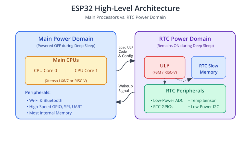
The ULP co-processor is an independent processing unit that resides within the ESP32’s RTC (Real-Time Clock) domain. Its key feature is its ability to operate while the main CPUs are powered down in deep sleep. This allows a device to perform periodic tasks without the power overhead of waking the entire system.
The ULP’s primary mission is simple: monitor and decide. It monitors peripherals, processes the data, and decides if a condition has been met to wake up the main CPU.
ULP Architecture and Variants
The ULP architecture is not the same across all ESP32 variants. It is crucial to understand which version you are working with.
- FSM (Finite State Machine) ULP: Found in the original ESP32. This is a very simple, custom-designed co-processor. Its instruction set is minimal and designed for sequential logic and peripheral access. It is programmed exclusively in a dedicated assembly language.
- RISC-V ULP: Found in ESP32-S2, ESP32-S3, ESP32-C6, and ESP32-H2. This is a more advanced co-processor based on a standard RISC-V architecture. This upgrade allows developers to write ULP code in C, making development significantly easier and more powerful.
| Feature | FSM (Finite State Machine) ULP | RISC-V ULP |
|---|---|---|
| Found In | Original ESP32 | ESP32-S2, ESP32-S3, ESP32-C6, ESP32-H2 |
| Programming Language | Dedicated Assembly Language | C / C++ (and Assembly) |
| Architecture | Simple, custom-designed state machine | Standard 32-bit RV32IMC RISC-V Core |
| Key Feature | Extremely low power for very simple, sequential tasks. | More powerful, flexible, and easier to program for complex logic. |
| Development Experience | Requires learning a unique instruction set. More challenging for complex logic. | Familiar C development environment, enabling more complex algorithms. |
Note: The ESP32-C3 does not have a ULP co-processor. It relies on other low-power modes and RTC functionality.
How the ULP Works
The ULP workflow involves three main stages:
- Initialization by the Main CPU:
- The main application, running on a primary core, writes the ULP program into a special section of memory called RTC slow memory. This memory region remains powered on during deep sleep.
- The main application configures the ULP timer. This timer determines how often the ULP program will wake up and execute. For example, you might set it to run every 5 seconds.
- The main application starts the ULP and then enters deep sleep.
- ULP Program Execution:
- The ULP timer expires, and the ULP co-processor begins executing the program stored in RTC slow memory.
- The ULP program can access peripherals in the RTC domain, such as specific GPIOs, the internal temperature sensor, and certain ADC channels.
- The ULP program performs its logic. For example, it might read an ADC value and compare it to a threshold stored in RTC slow memory.
- Wakeup or Halt:
- Condition Met: If the ULP program determines that the main CPU needs to be woken up (e.g., the sensor reading crossed a threshold), it executes a special
wakeinstruction. This sends a signal that wakes the ESP32 from deep sleep. - Condition Not Met: If the wakeup condition is not met, the ULP executes a
haltinstruction. This puts the ULP back to sleep until its timer triggers it again. The main CPUs remain in deep sleep.
- Condition Met: If the ULP program determines that the main CPU needs to be woken up (e.g., the sensor reading crossed a threshold), it executes a special
graph TD
    subgraph Main CPU Task
        A[Start: Main App Running];
        B{ULP Program Ready?};
        C[1- Load ULP program into<br>RTC Slow Memory];
        D["2- Configure ULP Timer<br>(e.g., run every 5s)"];
        E[3- Start ULP Co-Processor];
        F[4- Enter Deep Sleep];
    end

    subgraph "ULP Co-Processor Task (in RTC Domain)"
        G((ULP Timer Expires));
        H[ULP Wakes Up &<br>Executes Program];
        I["Access RTC Peripherals<br>(e.g., Read ADC Sensor)"];
        J{Evaluate Condition<br>e.g., ADC_VAL < THRESHOLD?};
        K[Condition Met: Execute WAKE instruction];
        L[Condition NOT Met: Execute HALT instruction];
    end

    subgraph System State
        M[Main CPU Wakes Up];
        N[Main CPU Stays in Deep Sleep];
    end

    %% Styling
    classDef starto-node fill:#EDE9FE,stroke:#5B21B6,stroke-width:2px;
    classDef process-node fill:#DBEAFE,stroke:#2563EB,stroke-width:1px;
    classDef decision-node fill:#FEF3C7,stroke:#D97706,stroke-width:1px;
    classDef check-node fill:#FEE2E2,stroke:#DC2626,stroke-width:1px;
    classDef success-node fill:#D1FAE5,stroke:#059669,stroke-width:2px;
    classDef endo-node fill:#F3F4F6,stroke:#6B7280,stroke-width:2px;

    class A,E starto-node;
    class C,D,H,I process-node;
    class B,J decision-node;
    class K,L check-node;
    class F,N endo-node;
    class M success-node;
    class G fill:#FEF9C3,stroke:#F59E0B,stroke-width:2px;

    %% Connections
    A --> B;
    B -->|"Yes"| C --> D --> E --> F;
    F --> G;
    G -.-> H;
    H --> I --> J;
    J -->|"True"| K --> M;
    J -->|"False"| L --> N;
    L -.-> G;
ULP Programming Model and Toolchain
The ESP-IDF provides a complete toolchain for ULP development.
- For FSM ULP (ESP32):
- You write code in a unique assembly language.
- The toolchain includes an assembler (
esp32-ulp-elf-as) and a linker. - In your project’s
CMakeLists.txt, you specify the assembly files (.S) to be processed. The build system automatically assembles them, links them, and generates symbol maps (.hand.ldfiles) that your main application can use to reference ULP variables and the program entry point.
- For RISC-V ULP (ESP32-S2/S3/C6/H2):
- You can write code in C, which is much more convenient.
- The toolchain uses a standard RISC-V GCC compiler (
riscv32-esp-elf-gcc). - The
CMakeLists.txtintegration is similar, but you specify C source files for the ULP component.
Practical Example: Wake on ADC Threshold (ESP32-S3 RISC-V ULP)
This example demonstrates how to use the RISC-V ULP on an ESP32-S3 to read an ADC channel periodically. If the reading is below a certain threshold (as if a light sensor detected darkness), it will wake the main CPU from deep sleep.
1. Project Setup
- Create a new project in VS Code using the ESP-IDF: New Project command. Choose the
esp-idf-templateand select the appropriate port and ESP32-S3 target. - Create a new component for the ULP code. A good practice is to keep ULP-related files separate. Create a directory named
ulp_riscv_adcinside acomponentsdirectory at the project root. - Inside
components/ulp_riscv_adc, create two files:ulp_main.candCMakeLists.txt.
2. ULP Component CMakeLists.txt
This file tells the build system how to handle the ULP C code.
File: components/ulp_riscv_adc/CMakeLists.txt
# CMakeLists.txt for the ULP component

# Define the ULP application details
ulp_app_create(ulp_riscv_adc_app          # Name of the ULP application
               "ulp_main.c"               # Source file for the ULP program
               "RTC_SLOW_MEM"             # Where to link the ULP binary (always this)
               )

# Register the ULP component with the build system
idf_component_register(SRCS              "ulp_main.c"
                       REQUIRES          ulp
                       EMBED_FILES       ${ulp_riscv_adc_app_out_bin}
                       EMBED_TXTFILES    ${ulp_riscv_adc_app_out_lst}
                       )

# Add a dependency on the ULP application for the main component
# This ensures ULP code is built before the main application
target_link_libraries(${COMPONENT_TARGET} INTERFACE ulp_riscv_adc_app)
3. ULP Program (ulp_main.c)
This is the C code that the RISC-V ULP will execute. It initializes an ADC, reads a value, compares it to a threshold, and wakes the main CPU if needed.
Hardware Setup: Connect a potentiometer or a photoresistor to GPIO1. This is ADC1_CH0 on many ESP32-S3 boards.
File: components/ulp_riscv_adc/ulp_main.c
#include "ulp_riscv.h"
#include "ulp_riscv_utils.h"
#include "ulp_riscv_gpio.h"
#include "ulp_riscv_adc_ulp_proc.h"
#include <stdint.h>

/* Global variables that can be accessed from the main CPU.
   These must be declared RTC_SLOW_ATTR to be placed in RTC slow memory.
*/
RTC_SLOW_ATTR uint32_t adc_reading;
RTC_SLOW_ATTR uint32_t wakeup_threshold = 1000; // Main CPU can change this value

/* Main entry point for the ULP program. */
int main(void)
{
    // Configure ADC
    // Note: ADC channel numbers map to GPIOs. Check your board's documentation.
    // GPIO1 is ADC1_CH0 on many ESP32-S3 devkits.
    const int adc_channel = ADC_CHANNEL_0;
    const int adc_unit = ADC_UNIT_1;

    // Configure the ADC unit
    ulp_riscv_adc_init(adc_unit);
    // Set attenuation for the channel. This determines the input voltage range.
    // 11dB gives a full range up to ~3.1V.
    ulp_riscv_adc_channel_config(adc_unit, adc_channel, ADC_ATTEN_DB_11);

    // --- Main ULP loop ---
    // This code runs every time the ULP is woken by its timer.

    // Perform an ADC reading
    adc_reading = ulp_riscv_adc_read(adc_unit, adc_channel);

    // Compare the reading with the threshold
    if (adc_reading < wakeup_threshold) {
        // If value is below threshold (e.g., it's dark), wake the main CPU.
        ulp_riscv_wakeup_main_processor();
    }

    // --- Halt the ULP ---
    // The ULP will halt here and wait for the next timer trigger.
    // The main CPUs remain in deep sleep unless woken up.
    return 0; // Returning from main is equivalent to halting
}
4. Main Application Code
This C code runs on the main CPU. It configures and starts the ULP, then enters deep sleep.
File: main/main.c
#include <stdio.h>
#include "freertos/FreeRTOS.h"
#include "freertos/task.h"
#include "esp_sleep.h"
#include "esp_log.h"
#include "driver/gpio.h"
#include "driver/rtc_io.h"
#include "ulp_riscv.h"

// Include the generated header file for the ULP program.
// This allows us to access the ULP binary and its global variables.
#include "ulp_riscv_adc_app.h"

static const char *TAG = "MAIN_CPU";

// Extern declaration for ULP variables defined in ulp_main.c
extern RTC_SLOW_ATTR uint32_t adc_reading;
extern RTC_SLOW_ATTR uint32_t wakeup_threshold;

void app_main(void)
{
    // Check the wakeup reason
    esp_sleep_wakeup_cause_t cause = esp_sleep_get_wakeup_cause();
    if (cause != ESP_SLEEP_WAKEUP_ULP) {
        ESP_LOGI(TAG, "Not a ULP wakeup, starting ULP program");

        // --- ULP Initialization ---
        // 1. Load the ULP program binary into RTC memory
        esp_err_t err = ulp_riscv_load_binary(ulp_riscv_adc_app_bin_start,
                                              (ulp_riscv_adc_app_bin_end - ulp_riscv_adc_app_bin_start));
        ESP_ERROR_CHECK(err);

        // 2. Set the ADC pin to an RTC GPIO to allow ULP access
        // ADC1_CH0 is GPIO1 on ESP32-S3
        rtc_gpio_init(GPIO_NUM_1);
        // Important: ADC pins must be isolated when in sleep mode
        rtc_gpio_isolate(GPIO_NUM_1);

        // 3. Set the ULP wakeup timer period (e.g., 2 seconds)
        // The ULP will run every 2000 ms.
        ulp_set_wakeup_period(0, 2000 * 1000);

        // 4. Set the wakeup threshold for the ULP program
        wakeup_threshold = 500; // Wake up if ADC reading is less than 500
        ESP_LOGI(TAG, "ULP wakeup threshold set to %" PRIu32, wakeup_threshold);

        // 5. Start the ULP program
        err = ulp_riscv_run();
        ESP_ERROR_CHECK(err);
        ESP_LOGI(TAG, "ULP coprocessor started.");

    } else {
        // --- Woken up by ULP ---
        ESP_LOGW(TAG, "Woken up by ULP!");
        ESP_LOGI(TAG, "Last ADC reading from ULP: %" PRIu32, adc_reading);
    }

    // --- Enter Deep Sleep ---
    ESP_LOGI(TAG, "Entering deep sleep...");
    // The main CPU will now sleep. The ULP will continue to run periodically.
    esp_deep_sleep_start();
}
5. Build, Flash, and Observe
- Configure: Run
idf.py menuconfig. Go toComponent config->ESP32-S3-Specific->ULP-RISC-V coprocessor. EnsureULP-RISC-V core enabledis checked. Save and exit. - Build: Use the ESP-IDF: Build your project command in VS Code (or run
idf.py build). - Flash: Use the ESP-IDF: Flash your project command (or run
idf.py -p [PORT] flash). - Monitor: Open the ESP-IDF monitor.
- On the first run, you will see the main CPU initialize the ULP and go to sleep.
- Adjust the potentiometer connected to GPIO1.
- When the ADC reading drops below the threshold (500), the ULP will wake the main CPU. You will see the “Woken up by ULP!” message, along with the ADC reading that triggered the event. The device will then re-enter deep sleep.
Variant Notes
- ESP32 (FSM ULP):
- Programming Language: Assembly only. The code is structured differently with labels and specific instructions like
rd_sar_adc,wake, andhalt. - Toolchain:
esp32-ulp-elf-toolchain is used. - Example Snippet (Assembly):
- Programming Language: Assembly only. The code is structured differently with labels and specific instructions like
| FSM ULP Assembly (ESP32) | RISC-V ULP C Code (ESP32-S3, etc.) |
|---|---|
| Task: Read an ADC value and wake the main CPU if it’s below a threshold. | |
// 1. Define memory locations .global adc_reading .global threshold // 2. Read ADC value into R0 rd_sar_adc ADC_UNIT_1, ADC_CH, R0 // 3. Store the reading in memory st R0, adc_reading, 0 // 4. Compare with threshold move R1, threshold sub R0, R0, R1 // If reading < threshold, result is negative jump_if_neg wake_up_label // 5. Condition not met, halt halt // 6. Wake up sequence wake_up_label: wake halt |
#include "ulp_riscv.h"
#include "ulp_riscv_adc_ulp_proc.h"

// 1. Define memory locations
RTC_SLOW_ATTR uint32_t adc_reading;
RTC_SLOW_ATTR uint32_t threshold;

int main(void) {
  // 2. Read ADC value
  adc_reading = ulp_riscv_adc_read(
      ADC_UNIT_1, ADC_CHANNEL_0
  );

  // 4. Compare with threshold
  if (adc_reading < threshold) {
    // 6. Wake up sequence
    ulp_riscv_wakeup_main_processor();
  }

  // 5. Condition not met, halt
  return 0; // Halts the ULP
}
|
- ESP32-S2: Has a RISC-V ULP, very similar to the ESP32-S3. The example code should work with minimal changes (mostly GPIO/ADC channel mapping).
- ESP32-C6 / H2: Also feature a RISC-V ULP. The programming principles are the same, but always consult the datasheet for the specific RTC peripherals and GPIOs available to the ULP on these chips.
Common Mistakes & Troubleshooting Tips
| Mistake / Issue | Symptom(s) | Troubleshooting / Solution |
|---|---|---|
| Forgetting RTC GPIO Config | ULP program runs, but sensor readings are always zero, max value (e.g., 4095), or nonsensical. | In the main CPU code, ensure you initialize the pin as an RTC GPIO before starting the ULP. Example: rtc_gpio_init(GPIO_NUM_1); |
| Wrong Memory Access | ULP crashes or behaves unpredictably. Debugging shows it halts unexpectedly. The main CPU never wakes up. | Ensure all variables shared between the main CPU and ULP are placed in RTC memory using the RTC_SLOW_ATTR macro. Check that the ULP code is only reading from/writing to these specific variables. |
| ULP Toolchain Build Errors | Build fails with errors like "ulp_riscv_... not found" or "esp32-ulp-elf-as: command not found". |
1. Verify the ESP-IDF environment is properly sourced in your terminal. 2. Run idf.py menuconfig and check under Component config -> ESP32...-Specific that the ULP core is enabled. |
| High Power Consumption in Sleep | Battery drains much faster than the expected microamps range. |
1. Confirm esp_deep_sleep_start() is actually being called. 2. Isolate external components to ensure they aren't drawing power. 3. Use rtc_gpio_isolate(GPIO_NUM_X); on unused RTC pins to prevent current leakage. |
| ULP Never Wakes Main CPU | The device goes to sleep and never prints the "Woken up by ULP!" message, even when the trigger condition is met. |
1. Use a simpler condition to test the wake mechanism (e.g., if (1) { wake; }). 2. "Debug" by writing intermediate ULP values to RTC_SLOW_ATTR variables. Wake the CPU with a timer instead of the ULP, and print the stored values to see the ULP's logic flow. |
Exercises
- Adjustable Threshold: Modify the main application code to set the
wakeup_thresholdbased on a value read from NVS (Non-Volatile Storage) at boot. - ULP Blink: Write a ULP program that toggles an RTC GPIO every time it runs. Observe the LED blinking at the ULP's wakeup interval while the main CPU is asleep. (You will need an oscilloscope or a very slow wakeup period to see this).
- ULP Event Counter: Create a
RTC_SLOW_ATTRvariable namedrun_count. Modify the ULP program to increment this counter every time it executes. In the main CPU code, print therun_countafter being woken up to see how many times the ULP ran before the wakeup condition was met. - Averaging Filter: (Advanced) Modify the ULP program to take 4 ADC readings in a row, calculate their average, and then compare the average value against the threshold. This helps prevent spurious wakeups due to noise.
Summary
- The ULP co-processor allows an ESP32 to perform simple tasks while the main CPUs are in deep sleep, dramatically saving power.
- The original ESP32 uses a simple FSM ULP programmed in assembly.
- Newer chips like ESP32-S2, S3, C6, H2 use a more powerful RISC-V ULP that can be programmed in C.
- ULP programs and shared data are stored in RTC slow memory, which is retained during deep sleep.
- The main CPU is responsible for loading the ULP program, setting its run interval, and initiating deep sleep.
- The ULP can wake the main CPU using a special
wakeinstruction when a specific condition is met. - Proper configuration of RTC GPIOs is essential for the ULP to interact with external sensors.
Further Reading
- ESP-IDF ULP Coprocessor Programming Guide (Latest): https://docs.espressif.com/projects/esp-idf/en/latest/esp32/api-reference/system/ulp.html
- ULP RISC-V Coprocessor Guide (for S2/S3/C6/H2): https://docs.espressif.com/projects/esp-idf/en/latest/esp32s3/api-reference/system/ulp_riscv.html
- ESP32 Technical Reference Manual: (Check the RTC chapter for in-depth hardware details) https://www.espressif.com/sites/default/files/documentation/esp32_technical_reference_manual_en.pdf
