
Chapter 260: USB CDC Implementation on ESP32-S2/3
Chapter Objectives
By the end of this chapter, you will be able to:
- Manually configure and initialize the USB driver for a Communications Device Class (CDC) device.
- Create a dedicated FreeRTOS task to manage the TinyUSB stack.
- Implement application logic to read data sent from a host PC over a virtual serial port.
- Write data from the ESP32 back to the host PC.
- Build a simple command-line interface controlled via USB.
- Understand the workflow for developing applications that use both the UART for debugging and native USB for primary communication.
Introduction
In the previous chapter, we saw how effortlessly we could redirect the system console to the native USB port using a simple menuconfig setting. This is incredibly useful for logging, but it only scratches the surface of what the native USB peripheral can do. The real power is unlocked when we take manual control of the USB stack.
By manually implementing a USB CDC device, you can create a dedicated, high-speed communication channel between your application and a host computer. This is essential for applications that need to receive commands, stream large amounts of sensor data, or present a custom command-line interface (CLI) for configuration and control.
This chapter will guide you through the process of setting up the TinyUSB stack manually, creating a robust two-way serial communication link, and building a practical, interactive application.
Theory
1. What is USB CDC, Really?
The Communications Device Class (CDC) is a composite USB class. This means it’s made up of multiple “interfaces.” For a virtual serial port, two are key:
- Communications Class Interface: This interface is used for control purposes—setting the virtual baud rate, parity, and other serial line parameters. Most of the time, TinyUSB and the operating system handle this automatically.
- Data Class Interface: This is the workhorse interface. It provides two “bulk” endpoints—one for sending data to the host (IN endpoint) and one for receiving data from the host (OUT endpoint). This is the channel through which our actual application data flows.
When you plug your ESP32 into a PC, and it enumerates as a CDC device, the PC’s operating system recognizes these interfaces and loads a standard driver, creating a virtual COM port that applications like a serial terminal can open and use.
graph TB
    subgraph "Host PC"
        A["PC Application<br>(e.g., PuTTY, Serial Monitor)"]
        B["Operating System<br><b>(Generic CDC Driver)</b>"]
    end

    subgraph "ESP32-S3 Device"
        D["TinyUSB Stack<br><i>(manages USB protocol)</i>"]
        E["ESP32 Application<br><b>(Your Code)</b>"]
    end

    C(USB Cable)

    %% Forward flow
    A --> B
    B --> C
    C --> D
    D --> E

    %% Reverse flow
    E --> D
    D --> C
    C --> B
    B --> A

    %% Add labels to connections
    A -.->|"Writes/Reads Data"| B
    B -.->|"USB Packets"| C
    C -.->|"USB Packets"| D
    D -.->|"API Calls<br>(tud_cdc_n_read/write)"| E

    %% Styling
    classDef pc fill:#DBEAFE,stroke:#2563EB,stroke-width:1px,color:#1E40AF
    classDef esp fill:#D1FAE5,stroke:#059669,stroke-width:2px,color:#065F46
    classDef transport fill:#FEF3C7,stroke:#D97706,stroke-width:1px,color:#92400E

    class A,B pc
    class D,E esp
    class C transport
2. The TinyUSB Application Workflow
When you don’t use the console redirection feature, you must manage the TinyUSB stack yourself. The workflow involves three main components:
- Initialization: You must explicitly initialize the TinyUSB stack by calling
tusb_init(). This sets up the necessary data structures and prepares the USB peripheral. - The TinyUSB Task: The USB protocol is event-driven and managed by the host. The TinyUSB stack needs to constantly check for and respond to events from the host (e.g., “the host sent you data,” “the host is ready to receive data”). This is handled by a function called
tud_task(). It is absolutely critical that this function is called repeatedly and frequently in your application. The standard practice is to dedicate a high-priority FreeRTOS task to this single purpose. - Application Interface: Your main application code interacts with the virtual serial port using the TinyUSB CDC API. This involves checking if data is available, reading it, and writing responses back.
flowchart TD
    A["Start: app_main()"] --> B(Initialize Peripherals<br>e.g., GPIO);
    B --> C{"Call <b>tusb_init()</b><br>Initialize TinyUSB Stack"};
    C --> D{"Create <b>tinyusb_task</b><br>(High Priority)"};
    C --> E{"Create <b>Application Task(s)</b><br>(e.g., cdc_cli_task)"};

    subgraph "FreeRTOS Task Scheduler"
        direction TB
        subgraph "Core 0"
            D_Task["<b>tinyusb_task</b>"]
            D_Task --> D_Loop{ }
            D_Loop -- "Repeats endlessly" --> D_Task_Action["Call <b>tud_task()</b><br><i>Handles USB events</i>"] --> D_Loop
        end
        subgraph "Core 1"
            E_Task["<b>Application Task</b>"]
            E_Task --> E_Action{"Check for input<br><i>tud_cdc_n_available()</i>"}
            E_Action --> E_Decision{Data available?}
            E_Decision -- Yes --> E_Process["Read & Process Data<br><i>tud_cdc_n_read()</i>"]
            E_Process --> E_Write["Write Response<br><i>tud_cdc_n_write()</i>"] --> E_Task
            E_Decision -- No --> E_Task
        end
    end

    D_Task_Action -.->|Data for App| E_Action
    E_Write -.->|Data for Host| D_Task_Action

    %% Styling
    classDef primary fill:#EDE9FE,stroke:#5B21B6,stroke-width:2px,color:#5B21B6;
    classDef process fill:#DBEAFE,stroke:#2563EB,stroke-width:1px,color:#1E40AF;
    classDef decision fill:#FEF3C7,stroke:#D97706,stroke-width:1px,color:#92400E;
    classDef task fill:#D1FAE5,stroke:#059669,stroke-width:2px,color:#065F46;

    class A,B,C,D,E primary;
    class D_Task,E_Task,D_Task_Action,E_Action,E_Process,E_Write task;
    class E_Decision decision;
3. Key TinyUSB CDC API Functions
The CDC driver in TinyUSB is designed to support multiple virtual serial ports. Therefore, its functions are often named with _n_ to specify the port number. For a single CDC device, this number will always be 0.
| Function Name | Description | Common Usage |
|---|---|---|
tud_cdc_n_connected(itf) |
Checks if the host serial terminal is open and connected to the CDC port. | Use in a loop to wait before sending an initial prompt, preventing data loss. |
tud_cdc_n_available(itf) |
Returns the number of bytes received from the host and waiting in the buffer. | Check if this is > 0 before calling read() to avoid reading empty data. |
tud_cdc_n_read(itf, buf, size) |
Reads available data from the internal USB buffer into your application’s buffer. | Call inside an if (tud_cdc_n_available(..)) block to process incoming commands. |
tud_cdc_n_write(itf, buf, size) |
Writes a buffer of data to be sent to the host. Also available as _str() and _char() variants. |
Used to send log data, command responses, and sensor readings to the PC. |
tud_cdc_n_write_flush(itf) |
Forces any data lingering in the write buffer to be sent to the host immediately. | Crucial for interactive CLIs. Call after writing a prompt or response to ensure the user sees it right away. |
Analogy: Think of
tud_task()as the postal worker for your ESP32’s USB port. The postal worker needs to constantly check the mailbox for incoming mail (host data) and pick up outgoing mail (ESP32 data). If the postal worker stays home (i.e., you don’t calltud_task()), mail piles up, and nothing gets delivered in either direction. Your application logic is like you, the homeowner, who reads the mail and writes replies.
Practical Example: USB Command-Line Interface
Let’s build an application that allows us to control the built-in RGB LED on a common ESP32-S3 development board via a command-line interface over USB. We will send commands like led on and led off from a serial terminal.
Project Goal: Create a manual USB CDC interface to control an LED.
Step 1: Project Setup and Configuration
- Create a new ESP-IDF project in VS Code. Set the target to ESP32-S3.
- Open
menuconfig(ESP-IDF: Launch SDK Configuration Editor). - Go to
Component Config—>TinyUSB Stack. - In the
Device Descriptorsubmenu, you can set a customProduct Namelike “ESP32-S3 CLI”. - In the
CDC-ACM (Serial port)submenu, ensureNumber of CDC-ACM portsis set to1. - Crucially, go back to
Component config->ESP System Settings->Channel for console outputand ensure it is set toDefault UART. We want ourESP_LOGmessages to go to the UART port for debugging, keeping the CDC port clean for our CLI. - Save and exit
menuconfig.
Step 2: Write the Application Code
Replace the contents of main/main.c with the following code. Note the comments explaining each part.
#include <stdio.h>
#include <string.h>
#include "freertos/FreeRTOS.h"
#include "freertos/task.h"
#include "esp_log.h"
#include "driver/gpio.h"
#include "tusb.h"
#include "tusb_cdc_acm.h"

// Define the GPIO for the onboard LED (this is for the ESP32-S3-DevKitC-1 v1.0)
// Check your board's schematic for the correct GPIO number.
#define BLINK_GPIO 48

static const char *TAG = "USB_CLI";

// Task to run the TinyUSB stack
void tinyusb_task(void *pvParameters)
{
    while (1) {
        // This is the main processing task for TinyUSB
        tud_task();
        // Give other tasks a chance to run
        vTaskDelay(pdMS_TO_TICKS(1));
    }
}

// Task to handle commands received over CDC
void cdc_cli_task(void *pvParameters)
{
    char command_buffer[64];
    int command_len = 0;

    // Wait until the CDC port is connected
    while (!tud_cdc_n_connected(0)) {
        vTaskDelay(pdMS_TO_TICKS(100));
    }
    ESP_LOGI(TAG, "CDC port connected");
    tud_cdc_n_write_str(0, "ESP32-S3 CLI Ready\r\n> ");
    tud_cdc_n_write_flush(0);


    while (1) {
        // Check if there is data to be read
        if (tud_cdc_n_available(0)) {
            uint8_t buf[64];
            uint32_t count = tud_cdc_n_read(0, buf, sizeof(buf));

            for(uint32_t i=0; i<count; i++) {
                // Echo the character back to the terminal
                tud_cdc_n_write_char(0, buf[i]);

                if (buf[i] == '\r' || buf[i] == '\n') {
                    // Terminate the command string
                    command_buffer[command_len] = '\0';
                    tud_cdc_n_write_str(0, "\r\n"); // New line for the response

                    // Process the command
                    if (strcmp(command_buffer, "led on") == 0) {
                        gpio_set_level(BLINK_GPIO, 1);
                        tud_cdc_n_write_str(0, "OK: LED is ON\r\n");
                    } else if (strcmp(command_buffer, "led off") == 0) {
                        gpio_set_level(BLINK_GPIO, 0);
                        tud_cdc_n_write_str(0, "OK: LED is OFF\r\n");
                    } else {
                        tud_cdc_n_write_str(0, "ERROR: Unknown command\r\n");
                    }

                    // Reset for the next command
                    tud_cdc_n_write_str(0, "> ");
                    tud_cdc_n_write_flush(0);
                    command_len = 0;
                } else if (command_len < sizeof(command_buffer) - 1) {
                    // Add character to buffer
                    command_buffer[command_len++] = buf[i];
                }
            }
             tud_cdc_n_write_flush(0);
        }
        vTaskDelay(pdMS_TO_TICKS(10));
    }
}


void app_main(void)
{
    ESP_LOGI(TAG, "Initializing USB CLI Application");

    // Configure the GPIO for the LED
    gpio_reset_pin(BLINK_GPIO);
    gpio_set_direction(BLINK_GPIO, GPIO_MODE_OUTPUT);

    // Initialize the TinyUSB stack
    ESP_LOGI(TAG, "USB initialization");
    tusb_init();

    // Create a task to run the TinyUSB driver
    xTaskCreate(tinyusb_task, "tinyusb_task", 4096, NULL, 5, NULL);

    // Create a task to handle our CLI
    xTaskCreate(cdc_cli_task, "cdc_cli_task", 4096, NULL, 4, NULL);
}
Step 3: Build, Flash, and Interact
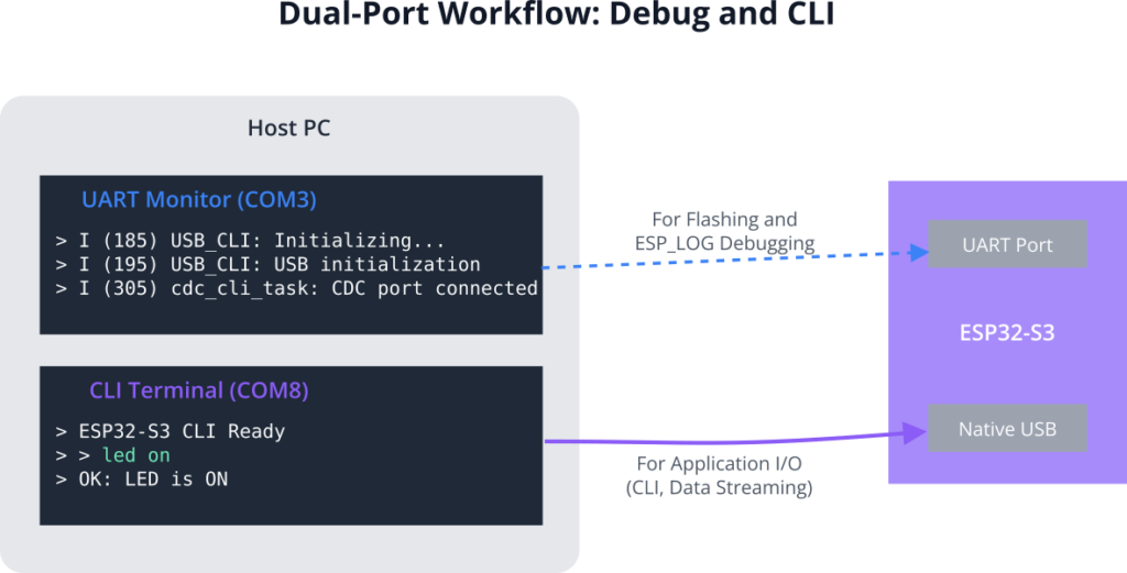
- Connect UART Port: Connect your ESP32-S3 board to your PC using the UART port.
- Flash: Build and flash the code using the standard VS Code command.
- Monitor UART: Open the ESP-IDF monitor on the UART COM port. You should see the
ESP_LOGImessages: “Initializing USB CLI Application” and “USB initialization”. - Connect Native Port: Now, connect a second USB cable to the Native USB port. Your PC should detect a new serial device.
- Monitor CDC Port: Open a second serial terminal (e.g., PuTTY, Tera Term, or the VS Code
ESP-IDF: Monitor Device (Select Port to Monitor)command on the new COM port). - Interact: Press Enter in the CDC terminal. You should see the
ESP32-S3 CLI Readyprompt. Now you can typeled onorled offand see the LED respond, with “OK” messages printed back to your terminal.
Variant Notes
- ESP32-S2/S3 Only: This functionality is exclusive to the S2 and S3 variants. Attempting to compile this code for other targets will result in build errors as the TinyUSB component will not be available for them.
- Performance on ESP32-S3: The dual-core architecture of the S3 is a significant advantage here. You can pin the
tinyusb_taskto one core and thecdc_cli_task(and other application logic) to the other. This ensures that even if your application is busy, the USB stack remains highly responsive, preventing dropouts. - Resource Usage on ESP32-S2: On the single-core S2, you must be more careful. If your application task performs a long, blocking operation, it can starve the
tinyusb_task, potentially causing the USB device to become unresponsive to the host. Keep application tasks short and use delays to yield processing time.
Common Mistakes & Troubleshooting Tips
| Mistake / Issue | Symptom(s) | Troubleshooting / Solution |
|---|---|---|
Forgetting tud_task() |
The device doesn’t show up on the PC at all, or it appears as an “Unknown Device” and is unresponsive. | Create a Task: Ensure you have a dedicated FreeRTOS task that does nothing but call tud_task() in a continuous loop. This task must have a high priority. |
| No Response in Terminal | You can send commands to the ESP32, but you never see the “OK” response or the next prompt. | Flush the Buffer: The data is likely sitting in the USB buffer. Call tud_cdc_n_write_flush(0) immediately after writing your response to force it to be sent to the PC. |
| Mixing up Ports | You type led on into the UART monitor and nothing happens, or you look for ESP_LOG messages in the CDC terminal and see nothing. |
Be Methodical: Use two separate terminal windows. Label one “DEBUG (UART)” and the other “CLI (Native USB)”. Always double-check which window you are typing in. |
| Blocking the USB Task | On an ESP32-S2, the USB connection works for a while but then becomes unresponsive, especially when the application is busy. | Don’t Block: Ensure your application tasks do not perform long, blocking operations. Use vTaskDelay() frequently to yield control so the high-priority tinyusb_task can run. |
Exercises
- ADC Data Logger: Write an application that reads a value from an ADC channel every second. Format this value into a CSV (Comma Separated Value) string like
"timestamp,adc_value\n"(e.g.,"12345,2048\n") and write it to the USB CDC port. You can then copy this output and paste it into a spreadsheet to graph the data. - RGB LED Controller: Extend the example to control the RGB components of the onboard LED. Implement commands like
rgb <r> <g> <b>(e.g.,rgb 255 0 128). This will require more advanced string parsing usingsscanforstrtok. - USB-to-UART Bridge: Turn your ESP32-S3 into a USB-to-UART converter. Initialize
UART1on two spare GPIOs. Write a task that reads from USB CDC and writes toUART1. Write a second task that reads fromUART1and writes to USB CDC. You can then use your S3 board to communicate with other serial devices.
Summary
- Manual USB CDC implementation gives you full control over a high-speed serial data channel to a host PC.
- The TinyUSB stack, integrated into ESP-IDF, provides the necessary APIs.
- The
tud_task()function is the heart of the USB stack and must be called continuously in a dedicated FreeRTOS task. - You can read and write data using the
tud_cdc_n_read()andtud_cdc_n_write()functions. - A common and robust design pattern is to use the UART port for debug logs and the native USB CDC port for the primary application I/O.
- This feature is only available on the ESP32-S2 and ESP32-S3.
Further Reading
- TinyUSB Device CDC Documentation: The official documentation for the TinyUSB CDC class provides details on all available functions.
- ESP-IDF USB Examples: ESP-IDF includes a dedicated example for a USB CDC-ACM device.
- Look in
examples/peripherals/usb/device/tusb_cdcin your ESP-IDF installation directory.
- Look in
