
Chapter 3: Real-World Examples of Embedded Systems
Chapter Objectives
Upon completing this chapter, you will be able to:
- Identify the pervasive role of embedded systems in consumer, automotive, industrial, and medical products.
- Describe the unique design constraints and challenges presented by each of these major application domains.
- Analyze the architecture of a common embedded system, such as an automotive ECU or a smart home device.
- Explain how system classifications (standalone, real-time, networked) apply to real-world products.
- Implement a prototype of an industrial monitoring system using a Raspberry Pi 5 to simulate a real-world application.
- Evaluate the trade-offs between cost, performance, reliability, and safety in different embedded contexts.
Introduction
Having established a framework for classifying embedded systems in the previous chapter, we now turn our attention to the world around us. Embedded systems are not abstract concepts confined to a laboratory; they are the invisible engines of modern life, silently powering the devices we depend on daily. From the moment you wake up to the sound of a digital alarm clock to the car that safely transports you to your destination, you are interacting with dozens, if not hundreds, of embedded systems. This chapter bridges the gap between theory and reality by taking a deep dive into specific, real-world applications across four major domains: consumer electronics, automotive, industrial automation, and medical devices.
Understanding these examples is vital for an aspiring embedded engineer. It contextualizes the design principles we have discussed and reveals the “why” behind the technical decisions. You will see how the hard real-time constraints discussed previously are a matter of life and death in an automotive braking system, how power efficiency becomes the paramount concern in a wearable fitness tracker, and how extreme reliability is non-negotiable in an industrial robot. By examining these case studies, you will develop a richer appreciation for the engineering trade-offs that shape our technological landscape. This exploration will culminate in a practical project where you use your Raspberry Pi 5 to build a simplified industrial control dashboard, transforming abstract concepts into a tangible, working prototype.
Technical Background
The true diversity and ingenuity of embedded engineering are best understood by examining its application in the wild. Each industry imposes a unique set of pressures—market, regulatory, environmental, and physical—that mold the final product. By dissecting examples from different fields, we can see our theoretical classifications manifest as concrete design choices.
The World of Consumer Electronics
Consumer electronics is perhaps the most visible and fast-paced domain for embedded systems. It is a world driven by intense competition, rapid innovation, and immense cost pressure. The goal is to deliver compelling features in an attractive package at a price point the mass market will accept. This relentless cycle forces engineers to make critical trade-offs between performance, power consumption, and bill of materials (BOM) cost.
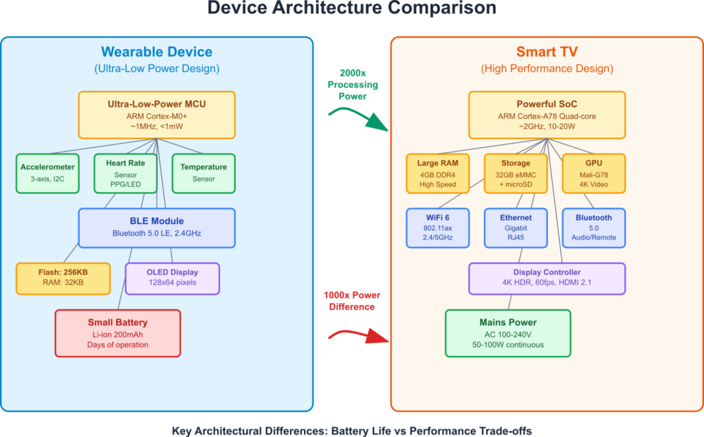
Consider the modern smart television. At its heart, it is a powerful networked, soft real-time embedded system. Its primary task is to decode and display high-resolution video streams, a computationally intensive process with soft real-time deadlines—dropping a frame occasionally degrades the experience but doesn’t cause a system failure. The core of a smart TV is a highly integrated System on a Chip (SoC), which combines multiple processor cores, a powerful Graphics Processing Unit (GPU), video decoding hardware, audio processors, and various I/O interfaces onto a single piece of silicon. This integration is key to reducing cost and size. The TV runs a sophisticated operating system, often a customized version of Linux or a proprietary OS like webOS or Tizen, which manages everything from the user interface to network connectivity and app execution. This is a far cry from the simple, standalone microcontrollers of older televisions, which merely had to respond to an infrared remote and change channels. Today’s TV is an IoT device, constantly connected to the internet, requiring robust network stacks, security protocols, and the ability to receive over-the-air (OTA) software updates.
Another ubiquitous example is the wearable fitness tracker. This device epitomizes the challenges of mobile embedded systems. The defining constraint is power. It must operate for days or even weeks on a tiny rechargeable battery. Every microampere of current is precious. Engineers achieve this through a combination of hardware and software strategies. They choose ultra-low-power microcontrollers, sensors that can be put into a deep sleep mode, and a simple, efficient display technology like OLED. The software is often a bare-metal application or a lightweight RTOS, meticulously designed to keep the main processor asleep as much as possible. It wakes up for brief intervals to read a sensor, update the display, and then immediately returns to a low-power state. It uses a power-efficient communication protocol like Bluetooth Low Energy (BLE) to periodically sync its data with a smartphone, offloading the heavy lifting of data analysis and visualization to the more powerful device.
The Automotive Revolution
Nowhere has the impact of embedded systems been more transformative than in the automotive industry. A modern car is a network on wheels, containing anywhere from 50 to over 150 individual Engine Control Units (ECUs). Each ECU is a dedicated embedded system responsible for a specific function, such as managing the engine, controlling the transmission, deploying airbags, or managing the climate control. This distributed architecture is a response to the immense complexity of the vehicle.
The Engine Control Unit (ECU) is a classic hard real-time system. It must precisely control fuel injection and spark timing in synchronization with the engine’s rotation, a process that requires calculations and actions on a microsecond timescale. A missed deadline could lead to engine damage, increased emissions, or poor performance. These ECUs are built for extreme reliability, designed to operate for years in a harsh environment of intense vibrations, temperature swings, and electrical noise.
These disparate ECUs must communicate with each other. This is accomplished through a specialized vehicle network, most commonly the Controller Area Network (CAN) bus. The CAN bus is a robust, message-based protocol designed to allow microcontrollers to communicate without a central host. For example, the wheel speed sensors (part of the ABS ECU) broadcast the speed of each wheel onto the CAN bus. The instrument cluster ECU listens for these messages to update the speedometer, while the transmission ECU might use the same data to decide when to shift gears. This creates a resilient, decentralized system.
graph TD
    subgraph "Anti-lock Braking System (ABS) ECU"
        A[Wheel Speed Sensors] -->|Sends Raw Data| B(ABS Controller);
    end

    subgraph "Vehicle Network"
        C((CAN Bus));
    end

    subgraph "Listening ECUs"
        D[Instrument Cluster ECU];
        E[Transmission Control Unit];
        F[Engine Control Unit];
    end

    B -->|Broadcasts <b>Wheel Speed: 75 km/h</b>| C;
    C -->|Message Received| D;
    C -->|Message Received| E;
    C -->|Message Received| F;

    D --> G{Update Speedometer};
    E --> H{Adjust Gear Shift Strategy};
    F --> I{Optimize Traction Control};

    classDef primary fill:#1e3a8a,stroke:#1e3a8a,stroke-width:2px,color:#ffffff;
    classDef process fill:#0d9488,stroke:#0d9488,stroke-width:1px,color:#ffffff;
    classDef system fill:#8b5cf6,stroke:#8b5cf6,stroke-width:1px,color:#ffffff;
    classDef success fill:#10b981,stroke:#10b981,stroke-width:2px,color:#ffffff;

    class A,B primary;
    class C system;
    class D,E,F process;
    class G,H,I success;
More recently, the rise of Advanced Driver-Assistance Systems (ADAS) and in-vehicle infotainment (IVI) has pushed automotive embedded systems to new heights of complexity. ADAS features like adaptive cruise control, lane-keeping assist, and automatic emergency braking rely on a suite of sensors—cameras, radar, LiDAR—and powerful processors capable of performing real-time sensor fusion and machine learning. These are safety-critical, hard real-time systems where failure is not an option. They must adhere to stringent functional safety standards like ISO 26262, which dictates a rigorous process for development, testing, and validation to minimize risk. The IVI system, by contrast, is a feature-rich, networked system, often running a high-level OS like Automotive Grade Linux or Android Automotive, that must balance soft real-time performance for media playback with the demands of navigation and connectivity.
The Backbone of Industry
In the industrial world, the focus shifts from the consumer’s desires to the factory’s demands: uptime, reliability, and precision. Industrial automation relies on embedded systems that are built to be incredibly robust and operate continuously for decades in challenging environments.
The workhorse of this domain is the Programmable Logic Controller (PLC). A PLC is a ruggedized embedded computer used for controlling manufacturing processes, such as assembly lines, robotic devices, or environmental controls. From the outside, it looks like a simple box with rows of screw terminals for connecting sensors and actuators. Inside, it runs a highly deterministic, real-time operating system. Its primary function is to execute a user-programmed logic loop, repeatedly reading the state of its inputs, executing a program (often written in a graphical language called Ladder Logic), and then updating its outputs. This scan cycle must be predictable and fast. PLCs are designed for modularity and fault tolerance, with redundant power supplies and processors available for critical applications.
flowchart TD
    subgraph Factory["Factory Floor (Physical Assets)"]
        A["Machine 1<br/>(Vibration, Temp Sensors)"]
        B["Machine 2<br/>(Power Consumption Sensor)"]
        C["Assembly Line<br/>(Optical Sensor)"]
    end

    subgraph Edge["Local Network (Edge Layer)"]
        D["<b>Edge Gateway</b><br/>(e.g., Raspberry Pi, Industrial PC)"]
        E["• Data Aggregation<br/>• Real-time Anomaly Detection<br/>• Local Control Logic"]
        F["• Local Dashboard"]
    end

    subgraph Cloud["Remote (Cloud Infrastructure)"]
        G["Cloud Platform<br/>(AWS, Azure, etc.)"]
        H["• Long-Term Storage<br/>• Advanced Analytics<br/>• Predictive Maintenance Models"]
        I["• Centralized Monitoring"]
    end

    A -->|"Raw Sensor Data"| D
    B -->|"Raw Sensor Data"| D
    C -->|"Raw Sensor Data"| D
    D -->|"Filtered/Analyzed Data"| G
    D -->|"Local Alerts/Actions"| F
    G -->|"Insights/Commands"| I

    classDef physical fill:#0d9488,color:#fff,stroke:#065f46
    classDef edge fill:#8b5cf6,color:#fff,stroke:#1f2937,stroke-width:2px
    classDef edgeDetails fill:#f0f9ff,color:#000,stroke:#8b5cf6
    classDef cloud fill:#1e3a8a,color:#fff,stroke:#1e40af
    classDef cloudDetails fill:#f0f9ff,color:#000,stroke:#1e3a8a

    class A,B,C physical
    class D edge
    class E,F edgeDetails
    class G cloud
    class H,I cloudDetails
The modern factory is evolving into the Industrial Internet of Things (IIoT), where machines are interconnected to enable predictive maintenance, improve efficiency, and allow for remote monitoring and control. This involves deploying thousands of embedded sensors to monitor machine health—vibration, temperature, power consumption. These sensors, often low-power wireless devices, send their data to an edge gateway. This gateway, which could be a device like an industrial PC or a powerful embedded platform like the Raspberry Pi, performs initial data filtering and analysis. It might run a machine learning model to detect anomalies locally, sending an alert only when a potential problem is found. This edge computing approach reduces the massive amount of data that needs to be sent to the cloud, saving bandwidth and enabling faster local responses. The communication protocols used here are robust industrial standards like Modbus, PROFINET, or EtherCAT, which are designed for deterministic, low-latency communication over Ethernet.
The High-Stakes World of Medical Devices
The final domain we will explore is medical technology, where the stakes are the highest. Embedded systems in this field are subject to the most stringent requirements for safety, reliability, and security, all overseen by rigorous regulatory bodies like the U.S. Food and Drug Administration (FDA).
Consider a hospital patient monitoring system. This device continuously tracks a patient’s vital signs—heart rate (ECG), blood oxygen level (SpO2), blood pressure, and respiration. This is a safety-critical, networked, real-time system. The algorithms that analyze the ECG waveform to detect arrhythmias must execute in real-time. The system must be able to trigger an alarm reliably and immediately if a vital sign crosses a critical threshold. A software bug or a missed deadline could have dire consequences for the patient. To ensure safety, the development process must follow strict standards like IEC 62304 (for software lifecycle processes) and ISO 14971 (for risk management). Every line of code must be traceable to a requirement and meticulously tested.
Another example is the infusion pump, a device used to deliver fluids, medication, or nutrients to a patient in controlled amounts. This is a hard real-time embedded system. It must control a motor with extreme precision to deliver a specific volume of liquid over a set period. An error in the delivery rate could lead to a dangerous under-dose or overdose. The software must include numerous safety checks, such as detecting air in the line or a blockage (occlusion). The user interface must be designed to be unambiguous and prevent user error, as a simple mistake in entering a number could be fatal. Furthermore, as these devices become networked to integrate with electronic health records, they must be secured against malicious attacks that could compromise patient safety. The design of a medical device is a multi-disciplinary effort, involving not just embedded engineers but also clinical experts, human factors engineers, and regulatory specialists.
Practical Examples
To make these concepts tangible, we will build a simplified prototype of an industrial monitoring dashboard. In this scenario, our Raspberry Pi 5 will act as an edge gateway. It will monitor the status of a “machine” (simulated with a button and an LED) and a critical process variable like temperature or pressure (simulated with a potentiometer). It will then serve a web page that acts as a live dashboard, accessible from any computer on the same network.
Warning: This project involves connecting to the Raspberry Pi’s GPIO pins. Ensure the Pi is powered off whenever you are making or changing connections. Use the correct resistor for the LED to avoid damaging the pin or the LED.
Hardware Required
- Raspberry Pi 5
- Breadboard and jumper wires
- 1x Tactile push button
- 1x LED (any color)
- 1x 330Ω resistor (for the LED)
- 1x 10kΩ potentiometer
- 1x MCP3008 Analog-to-Digital Converter (ADC)
Why the MCP3008? The Raspberry Pi’s GPIO pins are digital; they can only detect high (3.3V) or low (0V). They cannot read analog values, which vary continuously, like the output from a potentiometer. The MCP3008 is an ADC chip that reads analog voltages and converts them into digital values that the Pi can understand via the SPI protocol.
Build and Configuration Steps
- Enable SPI: The MCP3008 uses the SPI communication protocol.
- Open a terminal and run
sudo raspi-config. - Navigate to
3 Interface Options->I4 SPI. - Select
<Yes>to enable the SPI interface. - Reboot when prompted.
- Open a terminal and run
- Install Libraries: We need libraries for web development (Flask), GPIO control, and SPI communication for the ADC.
# Update package list
sudo apt update
# Install Flask web framework
pip install Flask
# Install Adafruit library for MCP3008
pip install adafruit-circuitpython-mcp3xxx
Hardware Integration
Wiring Diagram: This is the most complex part. Follow it carefully.
- LED:
- LED Anode (longer leg) -> 330Ω Resistor -> Raspberry Pi GPIO 17 (Pin 11)
- LED Cathode (shorter leg) -> Raspberry Pi GND (Pin 14)
- Button:
- One leg -> Raspberry Pi GPIO 27 (Pin 13)
- Opposite leg -> Raspberry Pi GND (Pin 20)
- MCP3008 ADC:
- Pin 16 (VDD) -> Raspberry Pi 3.3V (Pin 1)
- Pin 15 (VREF) -> Raspberry Pi 3.3V (Pin 1)
- Pin 14 (AGND) -> Raspberry Pi GND (Pin 9)
- Pin 13 (CLK) -> Raspberry Pi SCLK (GPIO 11, Pin 23)
- Pin 12 (DOUT/MISO) -> Raspberry Pi MISO (GPIO 9, Pin 21)
- Pin 11 (DIN/MOSI) -> Raspberry Pi MOSI (GPIO 10, Pin 19)
- Pin 10 (CS) -> Raspberry Pi CE0 (GPIO 8, Pin 24)
- Pin 9 (DGND) -> Raspberry Pi GND (Pin 9)
- Potentiometer:
- Left pin -> Raspberry Pi GND (Pin 25)
- Middle pin -> MCP3008 CH0 (Pin 1)
- Right pin -> Raspberry Pi 3.3V (Pin 1)
File Structure
Create a project directory and organize your files like this. This separation of concerns is good practice.
industrial_dashboard/
├── app.py              # The main Flask application and sensor logic
└── templates/
    └── index.html      # The HTML template for our web dashboard
Code Snippets
1. The Web Dashboard (templates/index.html)
This file uses basic HTML and a little JavaScript to fetch data from our Flask server every second and update the page without needing to reload.
<!-- templates/index.html -->
<!DOCTYPE html>
<html lang="en">
<head>
    <meta charset="UTF-8">
    <meta name="viewport" content="width=device-width, initial-scale=1.0">
    <title>Industrial Machine Dashboard</title>
    <style>
        body { font-family: sans-serif; background-color: #f0f2f5; margin: 0; padding: 2em; }
        .dashboard { max-width: 600px; margin: auto; background: white; padding: 2em; border-radius: 8px; box-shadow: 0 4px 8px rgba(0,0,0,0.1); }
        h1 { color: #333; text-align: center; }
        .status-box { padding: 1.5em; margin-top: 1em; border-radius: 6px; text-align: center; font-size: 1.5em; font-weight: bold; color: white; transition: background-color 0.5s; }
        .status-running { background-color: #28a745; }
        .status-stopped { background-color: #dc3545; }
        .parameter-box { margin-top: 1.5em; }
        label { font-weight: bold; color: #555; }
        progress { width: 100%; height: 30px; }
        #pressure-value { font-size: 1.2em; text-align: center; }
    </style>
</head>
<body>
    <div class="dashboard">
        <h1>Machine Monitoring</h1>

        <div id="machine-status" class="status-box">
            Loading...
        </div>

        <div class="parameter-box">
            <label for="pressure">Process Pressure:</label>
            <progress id="pressure" value="0" max="100"></progress>
            <p id="pressure-value">0 PSI</p>
        </div>
    </div>

    <script>
        function updateDashboard() {
            fetch('/data')
                .then(response => response.json())
                .then(data => {
                    // Update Machine Status
                    const statusDiv = document.getElementById('machine-status');
                    statusDiv.textContent = data.machine_status;
                    if (data.machine_status === 'RUNNING') {
                        statusDiv.className = 'status-box status-running';
                    } else {
                        statusDiv.className = 'status-box status-stopped';
                    }

                    // Update Pressure Gauge
                    document.getElementById('pressure').value = data.pressure_percent;
                    document.getElementById('pressure-value').textContent = data.pressure_psi + ' PSI';
                })
                .catch(error => console.error('Error fetching data:', error));
        }

        // Update every second
        setInterval(updateDashboard, 1000);
        // Initial load
        document.addEventListener('DOMContentLoaded', updateDashboard);
    </script>
</body>
</html>
2. The Flask Application (app.py)
This Python script does all the work: it sets up the GPIO pins, reads the sensors, and runs a web server to provide the data to the dashboard.
# app.py
from flask import Flask, render_template, jsonify
import time
import board
import busio
import digitalio
import adafruit_mcp3xxx.mcp3008 as MCP
from adafruit_mcp3xxx.analog_in import AnalogIn

# --- Flask App Setup ---
app = Flask(__name__)

# --- Hardware Initialization ---
# Create the SPI bus
spi = busio.SPI(clock=board.SCK, MISO=board.MISO, MOSI=board.MOSI)

# Create the chip select (CS)
cs = digitalio.DigitalInOut(board.D8) # Using CE0

# Create an MCP3008 object
mcp = MCP.MCP3008(spi, cs)

# Create an analog input channel on pin 0 for the potentiometer
pot_channel = AnalogIn(mcp, MCP.P0)

# Setup LED and Button pins
led = digitalio.DigitalInOut(board.D17)
led.direction = digitalio.Direction.OUTPUT

button = digitalio.DigitalInOut(board.D27)
button.direction = digitalio.Direction.INPUT
button.pull = digitalio.Pull.UP # Use internal pull-up resistor

# --- Helper Functions ---
def get_pot_value():
    """Reads the potentiometer and scales it to a percentage and PSI value."""
    # The ADC returns a 16-bit value (0-65535)
    raw_value = pot_channel.value
    # Scale to 0-100 for percentage
    percent = (raw_value / 65535) * 100
    # Scale to a simulated pressure range, e.g., 0-1500 PSI
    psi = (raw_value / 65535) * 1500
    return {"percent": round(percent), "psi": round(psi)}

def get_machine_status():
    """Reads the button to determine machine status and controls the LED."""
    # Button is pulled up, so False (0V) means it's pressed.
    if not button.value:
        led.value = True  # Turn LED on
        return "RUNNING"
    else:
        led.value = False # Turn LED off
        return "STOPPED"

# --- Web Routes ---
@app.route('/')
def index():
    """Serves the main dashboard page."""
    return render_template('index.html')

@app.route('/data')
def data():
    """This is the API endpoint our JavaScript will call."""
    status = get_machine_status()
    pressure = get_pot_value()

    # Return data as JSON
    return jsonify(
        machine_status=status,
        pressure_percent=pressure["percent"],
        pressure_psi=pressure["psi"]
    )

# --- Main Execution ---
if __name__ == '__main__':
    # To run this, find your Pi's IP address with `hostname -I`
    # Then access http://<your_pi_ip>:5000 from another device
    app.run(host='0.0.0.0', port=5000, debug=False)
Run and Verify
- Navigate to your project directory:
cd industrial_dashboard - Find your Raspberry Pi’s IP address:
hostname -I(note the first address shown). - Run the Flask application:
python app.py - On another computer, tablet, or phone connected to the same network, open a web browser and navigate to
http://<YOUR_PI_IP_ADDRESS>:5000. - Expected Output: You should see the “Industrial Machine Dashboard”.
- Initially, it should show “STOPPED” in a red box.
- Press and hold the button on your breadboard. The LED on the circuit should light up, and the dashboard status should change to “RUNNING” in a green box.
- Turn the potentiometer. The progress bar and the “PSI” reading on the dashboard should change in real-time, reflecting the potentiometer’s position.
This project, while simple, effectively demonstrates the architecture of an IIoT gateway, combining sensor input, actuator output, data processing, and network communication in a single embedded system.
Common Mistakes & Troubleshooting
When engineers move between domains, they can sometimes carry over assumptions that are inappropriate or even dangerous in the new context. Understanding these cross-domain fallacies is crucial.
Exercises
These exercises build upon the chapter’s concepts and the practical example, encouraging you to think more deeply about real-world design challenges.
- Enhancing the Industrial Dashboard with Data Logging:
- Objective: Add persistence to the industrial monitor, a common requirement for trend analysis and diagnostics.
- Task: Modify the
app.pyscript. Every time the/dataendpoint is called and the machine is “RUNNING”, append a timestamped JSON line containing the pressure reading to a log file (e.g.,pressure_log.csv). - Verification: Run the system for a minute while turning the potentiometer. Stop the script and inspect the
pressure_log.csvfile. It should contain a series of timestamped readings, which could be used later for analysis.
- Implementing a Critical Alert System:
- Objective: Simulate a safety-critical alert, a key feature of industrial and medical systems.
- Task: Add a “critical pressure” threshold to
app.py. If the pressure (PSI value) exceeds a certain limit (e.g., 1200 PSI), the web dashboard should display a prominent “OVER PRESSURE WARNING” message in flashing red text. This should override the normal display. - Verification: Run the application and turn the potentiometer past the threshold you set. The web page should immediately update with the flashing warning message. When you turn the pressure back down, the warning should disappear.
- Deconstructing a Real-World Device:
- Objective: Apply the chapter’s concepts to analyze a product you own.
- Task: Choose a common embedded device (e.g., a Wi-Fi router, a smart speaker, a microwave oven, or a digital camera). Research the device online. Try to identify:
- Its primary microcontroller or SoC.
- Its classification (standalone, networked, real-time?).
- Its main inputs and outputs.
- The likely design constraints (cost, power, performance, etc.).
- Verification: Write a short, one-page report summarizing your findings, explaining how the device’s components and features reflect its purpose and target market.
Summary
This chapter has demonstrated that the field of embedded systems is not monolithic but a rich tapestry of specialized domains, each with its own culture, constraints, and definition of success.
- Consumer Electronics is a fast-paced, cost-driven world where feature integration, user experience, and power efficiency in mobile devices are paramount.
- Automotive Systems are highly distributed, networked environments where hard real-time performance and functional safety (like ISO 26262) are critical for controlling everything from the engine to advanced driver-assistance features.
- Industrial Automation prioritizes extreme reliability, ruggedness, and long-term operational uptime, embodied by devices like PLCs and the emerging Industrial Internet of Things (IIoT).
- Medical Devices represent the apex of safety-critical design, governed by strict regulatory standards (like IEC 62304) where reliability and correctness can be a matter of life and death.
- Our practical example of an industrial dashboard showed how a platform like the Raspberry Pi 5 can be used to prototype a real-world edge computing gateway, integrating sensors, actuators, and a networked user interface.
By understanding these real-world contexts, you are now better prepared to make informed design decisions, appreciate the reasoning behind different system architectures, and tackle the unique challenges posed by any embedded systems project you may encounter.
Further Reading
- “Embedded Systems: A Contemporary Design Tool” by James K. Peckol. Offers excellent case studies and real-world examples across various industries.
- ISO 26262: Road vehicles – Functional safety. (iso.org) While the standard itself is a dense, formal document, reading summaries and white papers about it provides immense insight into the rigor of automotive design.
- IEC 62304: Medical device software – Software life cycle processes. (iec.ch) Similar to ISO 26262, understanding the framework of this standard is key to appreciating medical device development.
- “The Industrial Internet of Things (IIoT)” by Alasdair Gilchrist. Provides a comprehensive overview of the technologies, architectures, and business drivers behind the modern connected factory.
- “Automotive Embedded Systems Handbook” edited by Nicolas Navet and Françoise Simonot-Lion. A detailed handbook covering the specifics of automotive architectures, networking (CAN, LIN, FlexRay), and software.
- The EEVblog. (eevblog.com) An engineering blog and YouTube channel that often features teardowns of consumer, industrial, and test equipment, providing a practical look inside real embedded products.
