
Chapter 211: Insteon Dual-Band Protocol
Chapter Objectives
By the end of this chapter, you will be able to:
- Understand the fundamental principles of the Insteon protocol.
- Describe the benefits of a dual-band (RF and powerline) mesh network.
- Explain the structure of a standard Insteon message.
- Interface an ESP32 with an Insteon PowerLinc Modem (PLM) using UART.
- Write ESP-IDF C code to send commands to and receive messages from an Insteon network.
- Troubleshoot common issues when integrating ESP32 with Insteon systems.
Introduction
Welcome to the fascinating world of building automation. In previous chapters, we’ve explored various communication protocols, many of which rely on a single physical medium like radio frequency or a dedicated wire. In this chapter, we delve into Insteon, a unique protocol that takes a hybrid approach to ensure reliability.
Insteon is a home automation technology that simultaneously uses radio frequency (RF) and the existing electrical wiring (powerline) to communicate. This dual-band, or dual-mesh, approach creates a robust and self-healing network. If an RF signal is blocked by a thick wall, the message can still travel through the powerlines, and vice-versa. This makes it a compelling choice for reliable lighting and appliance control in residential and commercial environments.
While Insteon is a proprietary protocol, its power and reliability make it a valuable system to understand and integrate with. In this chapter, we will use an ESP32 not to create an Insteon device from scratch, but to act as a powerful, modern gateway to an existing Insteon network, allowing for IoT integration, custom logic, and cloud connectivity.
Theory
1. What is Insteon?
Insteon is a peer-to-peer networking technology for home automation. Unlike centralized systems where a hub is always required, Insteon devices can communicate directly with each other. A light switch can talk directly to a lamp module, or a sensor can directly trigger a siren. Every Insteon device acts as a repeater, retransmitting messages to extend the network’s range and improve its reliability.
| Feature | Insteon | Wi-Fi | Zigbee |
|---|---|---|---|
| Primary Topology | Dual-Band Mesh (Powerline + RF) | Star (Hub/Router to Devices) | Mesh (RF) |
| Reliability | Very High (self-healing, dual-path) | Moderate (depends on router quality & signal) | High (self-healing RF mesh) |
| Primary Medium | AC Powerline & 915 MHz RF | 2.4 GHz / 5 GHz RF | 2.4 GHz RF / 915 MHz RF |
| Typical Use Case | Lighting, Appliance Control, Sensors | High-Data Devices (Cameras, Streaming) | Low-Power Sensors, Lighting, Locks |
| Setup Complexity | Moderate (Linking required) | Simple (Password entry) | Moderate (Pairing/Joining required) |
| Inter-device Comm. | Direct (Peer-to-Peer) | Requires Router/AP | Direct (within the mesh) |
2. The Dual-Band Mesh Network
The core innovation of Insteon is its dual-mesh topology. Every Insteon-compatible device is equipped with both a powerline modem and an RF transceiver.
- Powerline (PL): Messages are transmitted as signals modulated onto the home’s existing 120V/240V AC wiring. This is highly effective as the communication infrastructure is already present in every room.
- Radio Frequency (RF): Messages are simultaneously broadcast wirelessly in the 915 MHz band (in North America). This allows communication between devices that are not on the same electrical phase or circuit, and for battery-powered devices like sensors.
This dual-band nature means that a single message is sent over both mediums. Other devices on the network hear the message on either RF or powerline and retransmit it on both mediums again. This creates a dense, redundant, and self-healing communication web.
graph TD
    subgraph Home Network
        direction TB
        Switch["Controller<br><b>(Switch)</b>"] -->|Sends Command| PL{Powerline}
        Switch -->|Sends Command| RF{Radio Frequency}

        PL ---->|Message via Powerline| Lamp["Responder<br><b>(Lamp)</b>"]
        RF ---->|Message via RF| Lamp

        PL ---->|Message Repeats| Repeater1[Outlet]
        RF ---->|Message Repeats| Repeater2[Sensor]

        Repeater1 -->|Repeats on Powerline| Lamp
        Repeater1 -->|Repeats on RF| Lamp
        Repeater2 -->|Repeats on Powerline| Lamp
        Repeater2 -->|Repeats on RF| Lamp
    end

    classDef start fill:#EDE9FE,stroke:#5B21B6,stroke-width:2px,color:#5B21B6;
    classDef end0 fill:#D1FAE5,stroke:#059669,stroke-width:2px,color:#065F46;
    classDef process fill:#DBEAFE,stroke:#2563EB,stroke-width:1px,color:#1E40AF;
    classDef decision fill:#FEF3C7,stroke:#D97706,stroke-width:1px,color:#92400E;

    class Switch start;
    class Lamp endo;
    class PL,RF,Repeater1,Repeater2 process;
3. Insteon Addressing and Linking
Each Insteon device has a unique 6-byte (48-bit) address, similar to a MAC address. For devices to work together, they must be linked. Linking is the process of creating a unidirectional connection between two devices.
- Controller: A device that initiates a command (e.g., a switch).
- Responder: A device that acts on a command (e.g., a lamp dimmer).
When you link a switch to a lamp, you are essentially telling the switch the address of the lamp and storing it in an internal database called the All-Link Database. You also program the lamp to listen for commands from that specific switch’s address. This creates a secure binding that prevents your neighbor’s Insteon system from controlling your lights.
4. The Insteon Message Structure
Insteon messages, whether sent over RF or powerline, follow a standard format. The two primary message types are:
- Standard Message: Used for most device control commands.
- Extended Message: Used for sending more complex data, like configuration settings or custom payloads.
A standard message is typically 9 bytes long and includes:
| Byte(s) | Field Name | Length | Example Value | Description |
|---|---|---|---|---|
| 1 | Flags | 1 Byte | 0x0F | Indicates message type (Standard), broadcast vs direct, and max hops. |
| 2-4 | To Address | 3 Bytes | AA.BB.CC | The unique address of the target device or group. |
| 5-7 | From Address | 3 Bytes | 11.22.33 | The unique address of the device sending the message (the PLM). |
| 8 | Command 1 (CMD1) | 1 Byte | 0x11 | The primary action to perform (e.g., ‘On’, ‘Off’, ‘Beep’). |
| 9 | Command 2 (CMD2) | 1 Byte | 0xFF | A parameter for CMD1 (e.g., On-Level, Dim Rate, Blink Speed). |
- Flags: Indicate message type, hops left, etc.
- To Address (3 bytes): The address of the destination device or group.
- From Address (3 bytes): The address of the sending device.
- Command 1 (CMD1): The primary command (e.g., “On”, “Off”, “Start Dimming”).
- Command 2 (CMD2): A parameter for the command (e.g., brightness level for “On”, ramp rate for dimming).
Analogy: Think of an Insteon message like a postal letter. The ‘To Address’ is the recipient’s address, the ‘From Address’ is the return address, and the ‘Commands’ are the contents of the letter telling the recipient what to do. The network itself is the postal service, using both air (RF) and ground (powerline) to make sure the letter gets delivered.
5. Interfacing with ESP32: The PowerLinc Modem (PLM)
Since the Insteon physical layer (the powerline and RF hardware) is proprietary, we cannot directly implement it on the ESP32’s GPIOs. Instead, we use an official Insteon interface device called a PowerLinc Modem (PLM), such as the Insteon 2413S.
The PLM is a serial modem. It connects to the powerline and has an RF transceiver, handling all the low-level complexities of the Insteon protocol. It exposes a simple serial (UART) interface that we can connect to our ESP32. We send commands to the PLM over UART, and it translates them into Insteon messages on the network. Conversely, it listens for Insteon traffic and translates it back into serial messages that our ESP32 can read.
The PLM’s serial protocol involves sending specific byte sequences to initiate actions and parsing incoming byte streams to understand what’s happening on the network.
Practical Examples
This example demonstrates how to use an ESP32 to communicate with an Insteon 2413S PLM to turn a linked light on and off.
Prerequisites
- Hardware:
- An ESP32 development board.
- An Insteon PLM (e.g., 2413S or 2412U). If using the 2413S, you’ll need a compatible serial-to-logic-level shifter if your board is not 5V tolerant, though many work fine directly.
- An Insteon-compatible device (e.g., a LampLinc or SwitchLinc) already linked to the PLM. For this example, we assume the device has address
AA.BB.CC. - Jumper wires.
- Software:
- VS Code with the ESP-IDF v5.x extension installed and configured.
- A new ESP-IDF project created.
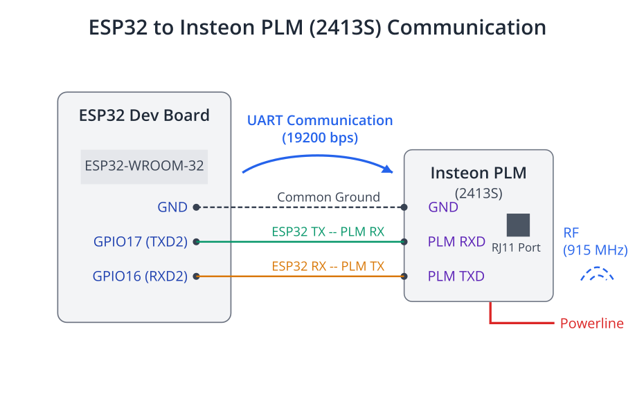
Step 1: Wiring the ESP32 to the Insteon PLM
The Insteon 2413S has a modular RJ11-style serial port. You will need to create a cable or use a breakout board to connect it to your ESP32. The pinout can be found in the PLM’s documentation. The key connections are:
- PLM RX to ESP32 TX
- PLM TX to ESP32 RX
- PLM GND to ESP32 GND
Warning: The Insteon 2413S PLM uses 5V logic levels. While many ESP32 GPIOs are 5V tolerant on the input (RX), the ESP32’s TX output is 3.3V. This is usually sufficient for the PLM’s RX to register the signal, but for production systems, a logic level shifter is recommended for reliability.
Let’s use UART2 for this example.
- ESP32 GPIO17 -> PLM TX
- ESP32 GPIO16 -> PLM RX
Step 2: Configure the Project in menuconfig
- Open the project terminal in VS Code.
- Run
idf.py menuconfig. - Go to
Component config->ESP System Settingsand ensureUART for console outputis set toDefault (UART0). We need to leave UART0 free for monitoring. - Save and exit.
Step 3: Writing the Code
We will create a component-based application. The main logic will be to construct a standard Insteon message and send it through the UART connected to the PLM.
---
config:
  theme: redux-color
---
sequenceDiagram
    participant ESP32
    participant PLM as Insteon PLM
    participant Device as Insteon Lamp
    ESP32->>+PLM: Sends Serial Cmd<br>(0x02, 0x62, AA.BB.CC, 0x0F, 0x11, 0xFF)
    PLM-->>-ESP32: ACKs Serial Cmd<br>(0x02, 0x62, ..., 0x06)
    Note over PLM, Device: PLM translates serial to Insteon<br>and sends over Powerline & RF
    PLM->>+Device: Insteon Message<br>LIGHT ON (0x11), Level 0xFF
    Device-->>-PLM: ACK (Standard Message)
    Note over PLM, Device: Lamp turns on to 100%
    Note over ESP32, PLM: PLM receives ACK and<br>translates back to serial
    PLM->>+ESP32: Receives Insteon Msg<br>(Standard Msg ACK from Device)
    ESP32-->>-PLM: (Parses and logs message)
Create a new C file, for example, insteon_control.c in your main directory.
/* main/insteon_control.c */

#include <stdio.h>
#include <string.h>
#include "freertos/FreeRTOS.h"
#include "freertos/task.h"
#include "driver/uart.h"
#include "esp_log.h"

static const char *TAG = "INSTEON_APP";

// --- UART Configuration ---
#define INSTEON_UART_NUM      UART_NUM_2
#define INSTEON_UART_TX_PIN   (17)
#define INSTEON_UART_RX_PIN   (16)
#define INSTEON_UART_RTS_PIN  (UART_PIN_NO_CHANGE)
#define INSTEON_UART_CTS_PIN  (UART_PIN_NO_CHANGE)
#define BUF_SIZE              (1024)

// --- Insteon Command Definitions ---
#define INSTEON_CMD_START_OF_TEXT   0x02
#define INSTEON_CMD_SEND_STD_MSG    0x62 // Command to send a standard Insteon message

// Insteon device commands
#define INSTEON_CMD_LIGHT_ON        0x11
#define INSTEON_CMD_LIGHT_OFF       0x13

/**
 * @brief Initialize the UART for Insteon PLM communication
 */
static void insteon_uart_init(void) {
    uart_config_t uart_config = {
        .baud_rate = 19200, // Insteon PLM uses 19200 baud
        .data_bits = UART_DATA_8_BITS,
        .parity    = UART_PARITY_DISABLE,
        .stop_bits = UART_STOP_BITS_1,
        .flow_ctrl = UART_HW_FLOWCTRL_DISABLE,
        .source_clk = UART_SCLK_DEFAULT,
    };
    // Install UART driver
    ESP_ERROR_CHECK(uart_driver_install(INSTEON_UART_NUM, BUF_SIZE * 2, 0, 0, NULL, 0));
    ESP_ERROR_CHECK(uart_param_config(INSTEON_UART_NUM, &uart_config));
    ESP_ERROR_CHECK(uart_set_pin(INSTEON_UART_NUM, INSTEON_UART_TX_PIN, INSTEON_UART_RX_PIN, INSTEON_UART_RTS_PIN, INSTEON_UART_CTS_PIN));
    ESP_LOGI(TAG, "Insteon UART driver initialized.");
}

/**
 * @brief Sends a standard Insteon command to a device via the PLM
 *
 * @param address Pointer to a 3-byte array holding the Insteon device address
 * @param cmd1 The primary command (e.g., ON/OFF)
 * @param cmd2 The secondary command (e.g., brightness level)
 */
void send_insteon_command(const uint8_t *address, uint8_t cmd1, uint8_t cmd2) {
    // A standard Insteon message to the PLM looks like this:
    // 0x02 (Start of Text)
    // 0x62 (Send Standard Message Command)
    // 3 bytes of device address
    // Flags (we use 0x0F for a standard direct message)
    // CMD1
    // CMD2
    uint8_t tx_buffer[8];
    tx_buffer[0] = INSTEON_CMD_START_OF_TEXT;
    tx_buffer[1] = INSTEON_CMD_SEND_STD_MSG;
    memcpy(&tx_buffer[2], address, 3);
    tx_buffer[5] = 0x0F; // Standard message flags, no extended data
    tx_buffer[6] = cmd1;
    tx_buffer[7] = cmd2;

    // Send the command over UART
    const int txBytes = uart_write_bytes(INSTEON_UART_NUM, tx_buffer, sizeof(tx_buffer));
    ESP_LOGI(TAG, "Sent %d bytes to PLM: 0x%02X 0x%02X %02X.%02X.%02X 0x%02X 0x%02X 0x%02X",
             txBytes, tx_buffer[0], tx_buffer[1], tx_buffer[2], tx_buffer[3], tx_buffer[4],
             tx_buffer[5], tx_buffer[6], tx_buffer[7]);
}

/**
 * @brief A task to listen for incoming data from the PLM
 */
static void insteon_rx_task(void *arg) {
    uint8_t* data = (uint8_t*) malloc(BUF_SIZE);
    while (1) {
        // Read data from the UART
        int len = uart_read_bytes(INSTEON_UART_NUM, data, (BUF_SIZE - 1), 20 / portTICK_PERIOD_MS);
        if (len > 0) {
            data[len] = '\0'; // Null-terminate for logging
            ESP_LOGI(TAG, "Received %d bytes from PLM.", len);
            // In a real application, you would parse this data to identify
            // incoming Insteon messages, acknowledgements, etc.
            // For now, we just print it.
            ESP_LOG_BUFFER_HEX(TAG, data, len);
        }
    }
    free(data);
}

void app_main(void) {
    // Initialize UART for PLM communication
    insteon_uart_init();

    // Start a task to handle receiving data from the PLM
    xTaskCreate(insteon_rx_task, "insteon_rx_task", 2048, NULL, 10, NULL);

    // --- IMPORTANT ---
    // Replace with the 3-byte address of YOUR Insteon device
    const uint8_t device_address[3] = {0xAA, 0xBB, 0xCC};

    ESP_LOGI(TAG, "Starting Insteon control loop...");

    while (1) {
        // Turn the light ON
        ESP_LOGI(TAG, "Sending 'LIGHT ON' command to %02X.%02X.%02X", device_address[0], device_address[1], device_address[2]);
        // The second command (0xFF) sets the brightness to full
        send_insteon_command(device_address, INSTEON_CMD_LIGHT_ON, 0xFF);
        vTaskDelay(5000 / portTICK_PERIOD_MS); // Wait 5 seconds

        // Turn the light OFF
        ESP_LOGI(TAG, "Sending 'LIGHT OFF' command to %02X.%02X.%02X", device_address[0], device_address[1], device_address[2]);
        send_insteon_command(device_address, INSTEON_CMD_LIGHT_OFF, 0x00);
        vTaskDelay(5000 / portTICK_PERIOD_MS); // Wait 5 seconds
    }
}
Step 4: Build, Flash, and Monitor
- Connect your ESP32 to your computer.
- Build the project by clicking the “Build” button in the VS Code status bar or running
idf.py build. - Flash the project using the “Flash” button or
idf.py -p [YOUR_PORT] flash. - Monitor the output using the “Monitor” button or
idf.py -p [YOUR_PORT] monitor.
You should see log messages indicating that the “LIGHT ON” and “LIGHT OFF” commands are being sent every 5 seconds. Your physical Insteon lamp module should respond by turning on and off accordingly. You will also see any traffic the PLM hears on the network printed in hexadecimal format by the insteon_rx_task.
Variant Notes
- ESP32, ESP32-S2, ESP32-S3, ESP32-C3, ESP32-C6: All of these variants have multiple UART peripherals and are perfectly capable of performing this task. The code provided uses
UART_NUM_2, which is available on most variants. If using a variant with fewer UARTs or different pin restrictions, you may need to changeINSTEON_UART_NUMtoUART_NUM_1and select appropriate GPIOs for that peripheral. Always consult the datasheet for your specific ESP32 variant to confirm pin capabilities. - ESP32-H2: This variant, focused on 802.15.4 protocols like Thread and Zigbee, also has UART controllers and can run this code without modification, provided the chosen GPIOs are available. The core logic is protocol-based over UART, making it highly portable across the ESP32 family.
The choice of variant for this application would likely be driven by other requirements, such as whether you also need Bluetooth (ESP32, S3, C6, H2) or advanced USB capabilities (S2, S3).
Common Mistakes & Troubleshooting Tips
| Mistake / Issue | Symptom(s) | Troubleshooting / Solution |
|---|---|---|
| Incorrect Wiring | Device does not respond. No data received from PLM in monitor. |
1. Verify ESP32 TX (GPIO17) -> PLM RX. 2. Verify ESP32 RX (GPIO16) -> PLM TX. 3. Ensure a common GND connection. |
| Wrong Baud Rate | UART monitor shows garbage data ( framing error). |
Set baud rate to 19200 in uart_config_t. The PLM is fixed at this speed.
|
| Incorrect Device Address | Code runs, sends commands, PLM may ACK, but the light/appliance does nothing. |
1. Find the 3-byte address on the device’s label. 2. Update the device_address array with the correct hex values.E.g., {0x1A, 0x2B, 0x3C}
|
| Device Not Linked to PLM | PLM sends the command, but the device ignores it completely. | Perform the Insteon linking process: Press and hold the SET button on the device, then send a linking command from the PLM (or use an app). |
| Logic Level Mismatch | Intermittent or unreliable communication. Commands sometimes work, sometimes don’t. | The PLM is 5V, ESP32 is 3.3V. While often working, for reliability add a bi-directional logic level shifter between ESP32 and PLM serial lines. |
| Not Parsing PLM Responses | Code sends commands “blindly.” You don’t know if they were received by the PLM or the device. |
Enhance insteon_rx_task to check for the PLM’s own ACK (0x06) after sending a command before assuming success.
|
Exercises
- Create a Dedicated Control Function: Refactor the code to create a function
set_light_state(const uint8_t *address, bool state)that takes the device address and a boolean (truefor on,falsefor off) as arguments. This will make the main loop cleaner. - Parse Incoming Messages: Modify the
insteon_rx_taskto be more intelligent. Read the Insteon PLM documentation and make the task identify and log when a standard Insteon message (0x50) is received from the network. It should print the From Address, To Address, and Commands from the received message. - Implement a Remote-Control Gateway: Modify your
app_mainto wait for a character from the console UART (UART0). If the user types ‘n’, call yourset_light_statefunction to turn the light on. If they type ‘f’, turn it off. This turns your ESP32 into a simple serial-to-Insteon bridge.
Summary
- Insteon is a reliable home automation protocol using a dual-band mesh network (Powerline and RF).
- Communication is peer-to-peer, and every device acts as a repeater, strengthening the network.
- Devices have unique 48-bit addresses and must be linked to communicate.
- We can interface with an Insteon network using an ESP32 and a PowerLinc Modem (PLM) connected via UART.
- The ESP32 sends specific byte commands to the PLM to control devices or get information.
- The UART communication is standard across all ESP32 variants, making this application highly portable.
- Robust implementation requires parsing responses from the PLM to confirm command delivery.
Further Reading
- Insteon Developer Documentation: https://support.insteon.com/documentation-listing
- The Insteon Hub 2413S/2412U Serial Protocol Guide: https://www.insteon.com/products/plm-serial-modem-interface?srsltid=AfmBOootv08Zmi5wYEpb_4YcnMaCw8dTIAEVGJC2Tq3witQqvFykmAlz
- Open-source Insteon Libraries: Explore libraries on GitHub (e.g., for Python or Arduino) to see more advanced parsing and logic for handling Insteon communication. These can serve as excellent references for building your own robust C component.
