
Chapter 219: HVAC Control Protocols Overview
Chapter Objectives
By the end of this chapter, you will be able to:
- Understand the fundamental components and goals of an HVAC system.
- Differentiate between simple on/off control and more advanced proportional control.
- Identify common physical and protocol-level interfaces for controlling HVAC equipment.
- Implement a functional smart thermostat on an ESP32 using a temperature sensor and relays.
- Apply control logic, including setpoints and hysteresis, in an embedded application.
- Recognize the methods for integrating custom ESP32 controllers with larger HVAC systems.
- Troubleshoot common hardware and software issues in a custom HVAC controller.
Introduction
Heating, Ventilation, and Air Conditioning (HVAC) systems are the single largest consumer of energy in most commercial and residential buildings. They are the invisible giants working tirelessly to keep us comfortable and healthy. Controlling these systems effectively is not just a matter of convenience; it is a critical factor in a building’s operational cost, energy footprint, and environmental impact.
In previous chapters, we’ve touched upon high-level BMS integration. Now, we dive into the heart of building automation: the direct control of its most energy-intensive subsystem. While modern HVAC equipment often uses sophisticated protocols like BACnet, the underlying control principles and many field-level interfaces are surprisingly fundamental.
This chapter will demystify HVAC control by focusing on these core principles. We will build our own smart thermostat using an ESP32, moving from theory to a hands-on application. This will provide a solid foundation for understanding how to interact with, control, and ultimately optimize the performance of real-world HVAC systems.
Theory
HVAC System Fundamentals
An HVAC system is a collection of equipment designed to control the environmental conditions within a space. The primary goal is to manage four key variables:
- Temperature: Heating in the winter, cooling in the summer.
- Humidity: Dehumidifying in humid climates, humidifying in dry ones.
- Ventilation: Introducing fresh outdoor air to maintain air quality.
- Air Filtration: Removing dust, pollen, and other pollutants.
A basic residential system typically consists of a furnace (for heat), an air conditioner (for cooling), and a blower fan that moves air through a network of ducts. In commercial buildings, these systems become far more complex, often involving chillers, boilers, cooling towers, and sophisticated air handling units (AHUs).
HVAC Control Loops
At its core, HVAC control is a classic feedback loop.
- Sense: A sensor (e.g., a thermostat) measures the current state of the environment (e.g., 24°C).
- Compare: A controller compares the current state to the desired state, or setpoint (e.g., 22°C).
- Act: Based on the difference (the “error”), the controller takes action by controlling an actuator (e.g., it turns on the air conditioner).
This loop continues until the error is minimized.
graph TD
    subgraph "Control Loop"
        A(Sense) -- "Current Temp: 24°C" --> B{Compare};
        B -- "Setpoint: 22°C<br><b>Error = 2°C</b>" --> C(Act);
        C -- "Turn On AC" --> D((Room Environment));
        D -- "Temperature Drops" --> A;
    end

    subgraph "Components"
        Thermostat[<b>Thermostat/Controller</b>]
        Sensor[Temperature Sensor]
        Actuator[HVAC Unit: AC/Heater]
    end

    A --- Sensor
    B --- Thermostat
    C --- Actuator

    style A fill:#DBEAFE,stroke:#2563EB,stroke-width:1px,color:#1E40AF
    style B fill:#FEF3C7,stroke:#D97706,stroke-width:1px,color:#92400E
    style C fill:#FEE2E2,stroke:#DC2626,stroke-width:1px,color:#991B1B
    style D fill:#D1FAE5,stroke:#059669,stroke-width:2px,color:#065F46

    style Sensor fill:#EDE9FE,stroke:#5B21B6,stroke-width:2px,color:#5B21B6
    style Thermostat fill:#EDE9FE,stroke:#5B21B6,stroke-width:2px,color:#5B21B6
    style Actuator fill:#EDE9FE,stroke:#5B21B6,stroke-width:2px,color:#5B21B6
Control Methods and Interfaces
How a controller “talks” to the HVAC unit varies widely.
- On/Off Control (Bang-Bang Control): This is the simplest method. If the temperature is too high, the AC is turned on at 100%. When the setpoint is reached, it’s turned off completely. This is common in residential thermostats. The interface is typically a set of dry-contact relays. For example, a standard US system uses color-coded wires:
- R (Red): 24V AC Power
- G (Green): Fan control
- Y (Yellow): Cooling control (compressor)
- W (White): Heating control (furnace)To turn on the heat, the thermostat simply closes a relay to connect the R wire to the W wire.
- Hysteresis: A crucial concept in on/off control is hysteresis, also known as a “deadband.” If your cooling setpoint is 22°C, you don’t want the AC to turn on at 22.01°C and off at 21.99°C. This rapid switching, or short cycling, would quickly destroy the equipment. Hysteresis creates a buffer. For example, with a 1°C hysteresis, the AC might turn on at 23°C and only turn off when the temperature drops to 21°C.
stateDiagram-v2
    direction LR

    [*] --> IDLE

    state "Cooling Logic" as Cooling {
        IDLE --> COOLING: Temp > Setpoint + Hysteresis<br>(e.g., > 23.0°C)
        COOLING --> IDLE: Temp <= Setpoint<br>(e.g., <= 22.0°C)
    }

    state "Heating Logic" as Heating {
         IDLE --> HEATING: Temp < Setpoint - Hysteresis<br>(e.g., < 21.0°C)
         HEATING --> IDLE: Temp >= Setpoint<br>(e.g., >= 22.0°C)
    }

    note right of Cooling
      <b>Setpoint = 22.0°C</b>
      <b>Hysteresis = 1.0°C</b>
      <b>Turn-On Point (Cool): 23.0°C</b>
      <b>Turn-Off Point (Cool): 22.0°C</b>
      This 1°C deadband prevents the AC from
      "short cycling" around the setpoint.
    end note

    style Cooling fill:#DBEAFE,stroke:#2563EB,stroke-width:1px
    style Heating fill:#FEE2E2,stroke:#DC2626,stroke-width:1px
- Proportional Control: More advanced systems (like Variable Air Volume, or VAV boxes) don’t just turn on and off. They can modulate their output. A cooling valve might be 25% open, 50% open, or anywhere in between. The interface for this is often an analog signal, such as a 0-10V DC or 4-20mA signal, where the voltage or current level corresponds to the desired output.
- Protocol-Based Control: Modern, complex HVAC equipment is often controlled via a digital protocol. The automation controller communicates with the equipment using a standard like Modbus RTU or BACnet MS/TP over a serial bus (typically RS-485). Instead of closing a relay, the controller sends a digital command like “Set Fan Speed to 75%” or “Set Damper Position to 40 degrees.”
| Control Method | Physical Interface | Control Signal | Typical Use Case | ESP32 Implementation |
|---|---|---|---|---|
| On/Off (Bang-Bang) | Relay (Dry Contact) | Binary (On/Off) | Residential thermostats, simple equipment | Easy: Control GPIOs connected to a relay module. |
| Proportional | Analog I/O | Analog Voltage (0-10V) or Current (4-20mA) | VAV boxes, dampers, valve actuators | Medium: Requires a DAC (Digital-to-Analog Converter) or PWM with an RC filter. |
| Protocol-Based | Serial Bus (RS-485) or Ethernet | Digital Packets (e.g., Modbus, BACnet) | Modern commercial/industrial HVAC units (AHUs, chillers) | Advanced: Requires a protocol stack library (like esp-modbus) and often an RS-485 transceiver. |
Our focus will be on the on/off relay control method, as it’s the most fundamental and provides a clear basis for building a custom controller.
Practical Example: ESP32 Smart Thermostat
Let’s build a simple smart thermostat that reads temperature and humidity and controls two relays: one for a heater and one for an air conditioner.
Hardware Requirements
- ESP32 Development Board.
- Temperature/Humidity Sensor: A DHT22 (or AM2302) is a good, low-cost choice. An SHT31 or BME280 would offer higher accuracy.
- 2-Channel Relay Module: A module that can be safely controlled by the ESP32’s 3.3V logic levels. Ensure the relays are rated for the voltage/current of the devices you want to control (e.g., 24VAC for standard HVAC or 120/240V AC for a space heater/fan).
- Jumper Wires.
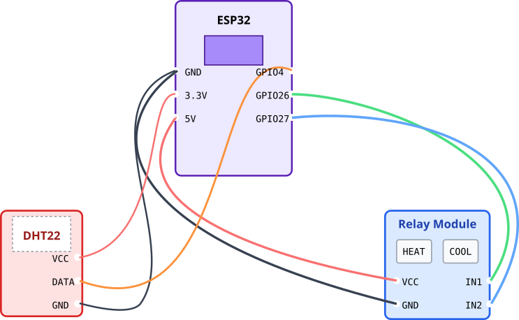
Wiring:
- DHT22 Sensor:
- VCC -> ESP32 3.3V
- GND -> ESP32 GND
- DATA -> ESP32 GPIO pin (e.g., GPIO 4)
- Relay Module:
- VCC -> ESP32 5V (if the module requires it) or 3.3V
- GND -> ESP32 GND
- IN1 (Heater) -> ESP32 GPIO pin (e.g., GPIO 26)
- IN2 (Cooler) -> ESP32 GPIO pin (e.g., GPIO 27)
Warning: When connecting relays to actual HVAC equipment or mains voltage, exercise extreme caution. Mis-wiring can damage your equipment and poses a serious safety risk. If you are unsure, consult a qualified electrician. For testing, you can simply connect LEDs to the relay outputs.
Project Setup and Component
This project requires a component for the DHT22 sensor. A popular and easy-to-use one is idf-dht.
- Create a new ESP-IDF project.
- Create a
componentsfolder in your project root. - Clone the
idf-dhtrepository into this folder: https://github.com/UncleRus/idf-dht
Smart Thermostat Code
The code below sets up the sensor and relays and implements the core thermostat logic in a FreeRTOS task.
stateDiagram-v2
    [*] --> SYSTEM_IDLE

    SYSTEM_IDLE: Relays OFF
    SYSTEM_HEATING: Heater Relay ON
    SYSTEM_COOLING: Cooler Relay ON

    SYSTEM_IDLE --> SYSTEM_HEATING: temp < (setpoint - hysteresis)
    SYSTEM_HEATING --> SYSTEM_IDLE: temp >= setpoint

    SYSTEM_IDLE --> SYSTEM_COOLING: temp > (setpoint + hysteresis)
    SYSTEM_COOLING --> SYSTEM_IDLE: temp <= setpoint

    style SYSTEM_IDLE fill:#DBEAFE,stroke:#2563EB,stroke-width:2px,color:#1E40AF
    style SYSTEM_HEATING fill:#FEE2E2,stroke:#DC2626,stroke-width:1px,color:#991B1B
    style SYSTEM_COOLING fill:#D1FAE5,stroke:#059669,stroke-width:1px,color:#065F46
/*
 * Chapter 219: HVAC Control - ESP32 Smart Thermostat
 *
 * This example implements a simple thermostat with heating and cooling control.
 * It uses a DHT22 sensor to read temperature and controls two relays.
 *
 * Hardware:
 * - ESP32 board
 * - DHT22 sensor
 * - 2-Channel Relay Module
 */
#include <stdio.h>
#include "freertos/FreeRTOS.h"
#include "freertos/task.h"
#include "esp_log.h"
#include "dht.h" // From idf-dht component
#include "driver/gpio.h"

static const char *TAG = "HVAC_THERMOSTAT";

// --- Configuration ---
#define SENSOR_PIN          (GPIO_NUM_4)
#define HEATER_RELAY_PIN    (GPIO_NUM_26)
#define COOLER_RELAY_PIN    (GPIO_NUM_27)

// --- Thermostat Logic Settings ---
#define TEMP_SETPOINT_C     22.0f // Desired temperature in Celsius
#define HYSTERESIS_C        1.0f  // Hysteresis value of 1 degree

typedef enum {
    SYSTEM_IDLE,
    SYSTEM_HEATING,
    SYSTEM_COOLING
} hvac_state_t;

static hvac_state_t current_state = SYSTEM_IDLE;

void setup_gpio(void) {
    gpio_reset_pin(HEATER_RELAY_PIN);
    gpio_reset_pin(COOLER_RELAY_PIN);
    // Relays are often active-low, but we configure as active-high for clarity.
    // If your relays turn on with a LOW signal, invert the logic in the task.
    gpio_set_direction(HEATER_RELAY_PIN, GPIO_MODE_OUTPUT);
    gpio_set_direction(COOLER_RELAY_PIN, GPIO_MODE_OUTPUT);

    // Ensure relays are off initially
    gpio_set_level(HEATER_RELAY_PIN, 0);
    gpio_set_level(COOLER_RELAY_PIN, 0);
}

void thermostat_control_task(void *pvParameters) {
    float temperature, humidity;

    // DHT22 requires a 2-second startup time
    vTaskDelay(pdMS_TO_TICKS(2000));

    while (1) {
        // 1. SENSE: Read the current temperature
        if (dht_read_float_data(DHT_TYPE_AM2301, SENSOR_PIN, &humidity, &temperature) == ESP_OK) {
            ESP_LOGI(TAG, "Temperature: %.1f°C, Humidity: %.1f%%, State: %s",
                     temperature, humidity,
                     (current_state == SYSTEM_IDLE) ? "IDLE" :
                     (current_state == SYSTEM_HEATING) ? "HEATING" : "COOLING");

            // 2. COMPARE: Apply thermostat logic
            switch (current_state) {
                case SYSTEM_IDLE:
                    if (temperature < (TEMP_SETPOINT_C - HYSTERESIS_C)) {
                        current_state = SYSTEM_HEATING;
                        ESP_LOGW(TAG, "Too cold! Turning ON heater.");
                        gpio_set_level(HEATER_RELAY_PIN, 1);
                    } else if (temperature > (TEMP_SETPOINT_C + HYSTERESIS_C)) {
                        current_state = SYSTEM_COOLING;
                        ESP_LOGW(TAG, "Too hot! Turning ON cooler.");
                        gpio_set_level(COOLER_RELAY_PIN, 1);
                    }
                    break;

                case SYSTEM_HEATING:
                    if (temperature >= TEMP_SETPOINT_C) {
                        current_state = SYSTEM_IDLE;
                        ESP_LOGW(TAG, "Setpoint reached. Turning OFF heater.");
                        gpio_set_level(HEATER_RELAY_PIN, 0);
                    }
                    break;

                case SYSTEM_COOLING:
                    if (temperature <= TEMP_SETPOINT_C) {
                        current_state = SYSTEM_IDLE;
                        ESP_LOGW(TAG, "Setpoint reached. Turning OFF cooler.");
                        gpio_set_level(COOLER_RELAY_PIN, 0);
                    }
                    break;
            }
        } else {
            ESP_LOGE(TAG, "Could not read data from sensor");
        }

        // Wait for 5 seconds before the next reading/logic cycle
        vTaskDelay(pdMS_TO_TICKS(5000));
    }
}

void app_main(void) {
    setup_gpio();
    xTaskCreate(thermostat_control_task, "thermostat_control_task", 4096, NULL, 5, NULL);
}
Build, Flash, and Run
- Connect Hardware: Wire the sensor and relay module to your ESP32.
- Build: Click the Build button in VS Code.
- Flash: Connect the ESP32 and click the Flash button.
- Monitor: Open the serial monitor. You will see temperature/humidity readings and status messages as the thermostat logic activates. Try warming the sensor with your hand or cooling it with a cold object to trigger the heating and cooling states.
Variant Notes
- All ESP32 Variants: This example is fundamentally about GPIO control and sensor reading, making it compatible with all ESP32 variants (ESP32, S2, S3, C-series, H-series). The primary consideration is selecting available GPIO pins that do not conflict with other functions.
- ESP32-S2/S3: These variants have a high-accuracy internal temperature sensor. You could adapt the code to use this built-in sensor instead of an external DHT22 for a simpler hardware setup, though an external sensor placed correctly in the room will always provide a more representative room temperature reading.
- Power Consumption: For a battery-powered thermostat, an ESP32-C3 or C6 would be a good choice due to their lower power consumption profiles. The control logic would need to be adapted to work with deep sleep cycles, waking up periodically to check the temperature and take action.
Common Mistakes & Troubleshooting Tips
| Mistake / Issue | Symptom(s) | Troubleshooting / Solution |
|---|---|---|
| Sensor Reads Failing | Log output shows Could not read data from sensor. Temperature is always 0. |
1. Check Wiring: Verify VCC, GND, and DATA pin connections are correct and secure. 2. Pull-up Resistor: The DHT22’s data line often requires a 4.7kΩ to 10kΩ pull-up resistor connected between DATA and 3.3V. 3. Component Install: Ensure the idf-dht library is cloned into the components/ folder. |
| Relay Not Clicking | Log shows “Turning ON heater/cooler” but the relay module’s LED doesn’t light up and there’s no audible click. |
1. Power: Check if the relay module’s VCC is connected correctly. Some modules need 5V, not 3.3V, to operate the relay coils. 2. GPIO Pin: Confirm you are using the correct GPIO pin defined in the code. |
| Relay Always On or Inverted | The relay turns ON when the log says it should be OFF, or vice-versa. |
Many relay modules are active-low. This means a LOW signal (0) turns them ON. If this is the case, invert the logic in your code: gpio_set_level(…, 0); // To turn ON gpio_set_level(…, 1); // To turn OFF |
| Thermostat “Flapping” | The system rapidly switches between IDLE and HEATING/COOLING states every few seconds. | The HYSTERESIS_C value is too small. A value of 0 prevents any deadband. Increase it to at least 0.5 or 1.0 to create a stable buffer around the setpoint and prevent equipment damage. |
| ESP32 Reboots Randomly | The device works for a while then unexpectedly resets. | This can be a power issue. The power draw when a relay coil energizes can cause a voltage drop, resetting the ESP32. Ensure you have a stable power supply that can handle the combined load. Adding a large capacitor (e.g., 470µF) across the ESP32’s power input pins can help. |
Exercises
- Add a Display: Integrate a simple I2C OLED display (like an SSD1306) to show the current temperature, humidity, setpoint, and system state (Idle, Heating, Cooling).
- Web-Based Control: Add Wi-Fi connectivity and a basic HTTP web server (see Chapter 112). Create a simple web page that displays the current status and allows you to change the
TEMP_SETPOINT_Cvalue from your web browser. - Implement a Fan Mode: Add a third state for “Fan Only” operation. This can be controlled by another GPIO connected to the “G” wire of a standard thermostat connection. Add logic to run the fan periodically to circulate air, even when not heating or cooling.
- BMS Integration: Combine this chapter with the previous one. Expose the current temperature, humidity, and system state as Modbus TCP registers, allowing a central BMS to monitor your custom thermostat.
Summary
- HVAC control is a core function of building automation, focused on managing temperature and air quality while optimizing energy.
- Simple on/off relay control is a fundamental method for interfacing with many HVAC units.
- Hysteresis is a critical software concept used to prevent rapid on/off switching (short cycling) that can damage equipment.
- More advanced systems use proportional control (e.g., 0-10V signals) or digital protocols like Modbus RTU and BACnet.
- The ESP32 is an ideal platform for creating custom smart thermostats and HVAC controllers due to its powerful processing, flexible GPIO, and built-in connectivity.
- Proper hardware wiring and robust control logic are the keys to building a safe and effective HVAC controller.
Further Reading
- ESP-IDF GPIO Documentation: https://docs.espressif.com/projects/esp-idf/en/v5.1.1/esp32/api-reference/peripherals/gpio.html
- DHT Sensor
idf-dhtComponent: https://github.com/UncleRus/idf-dht - HVAC Control Basics (External Resource): A good primer on general HVAC theory. https://www.carrier.com/commercial/en/us/service-support/hvac-basics/
