
Chapter 204: DALI (Digital Addressable Lighting Interface)
Chapter Objectives
Upon completing this chapter, students will be able to:
- Understand the fundamentals of the DALI protocol and its architecture.
- Explain the DALI physical layer, including wiring, signaling, and Manchester encoding.
- Describe DALI addressing schemes (short, group, broadcast).
- Understand the structure of DALI commands and their purpose.
- Recognize the role of DALI in modern lighting control systems.
- Implement basic DALI master functionality on an ESP32 using the RMT peripheral.
- Send DALI commands to control DALI-compliant lighting ballasts.
- Identify common issues and troubleshoot DALI implementations on ESP32.
- Appreciate the differences in implementing DALI across various ESP32 variants.
Introduction
Welcome to Chapter 204. In the realm of building automation and intelligent lighting, precise and flexible control of lighting fixtures is paramount. Traditional lighting systems often rely on simple on/off switches or basic dimmers, offering limited functionality. The Digital Addressable Lighting Interface (DALI) emerges as a powerful solution, providing a standardized, two-wire digital communication protocol specifically designed for controlling lighting equipment such as ballasts, LED drivers, and emergency lighting.
DALI allows for individual addressing and control of light sources, enabling sophisticated lighting scenes, energy savings through dimming and daylight harvesting, and status reporting from the fixtures themselves. Its robustness, scalability, and interoperability have made it a cornerstone in commercial, industrial, and high-end residential lighting systems.
In this chapter, we will delve into the intricacies of the DALI protocol. We will explore its theoretical underpinnings, from the physical layer to command structures. Crucially, we will then transition to practical implementation, demonstrating how an ESP32 microcontroller, with its versatile RMT (Remote Control) peripheral, can act as a DALI master to control DALI-enabled devices. This knowledge will empower you to integrate intelligent lighting control into your ESP32-based building automation projects.
Theory
What is DALI?
DALI, which stands for Digital Addressable Lighting Interface, is an international standard (IEC 62386) for communication between lighting control devices and lighting equipment (control gear). It defines a digital, bi-directional communication protocol over a simple two-wire bus. Unlike analog systems like 0-10V, DALI offers individual addressing, status feedback, and a richer set of control commands.
Key Features of DALI:
- Standardized Protocol: Ensures interoperability between devices from different manufacturers (especially with DALI-2 certification).
- Two-Wire Bus: Simple, polarity-insensitive wiring reduces installation complexity and cost.
- Digital Communication: Provides precise control and noise immunity compared to analog systems.
- Individual Addressing: Each DALI control gear (e.g., an LED driver or ballast) can be assigned a unique short address (0-63).
- Group Addressing: Control gear can be assigned to one or more groups (0-15) for simultaneous control.
- Broadcast: Commands can be sent to all connected devices.
- Bi-directional Communication: Allows the master to send commands and the control gear to send back status information or acknowledge commands.
- Scene Control: Pre-programmed lighting levels can be stored in the control gear and recalled with a single command.
- Status Reporting: Control gear can report lamp status, ballast failure, power levels, etc.
- Integrated Bus Power: The DALI bus can also provide limited power to some control devices, though the primary DALI bus power supply is for communication and control gear logic.
| Feature | Description | Benefit |
|---|---|---|
| Standardized Protocol | Defined by international standard IEC 62386. DALI-2 certification ensures strict interoperability. | Guarantees that devices from different manufacturers can work together reliably. |
| Two-Wire Bus | Uses a simple, unshielded, polarity-insensitive two-wire cable for communication and power. | Reduces wiring complexity, installation time, and material costs. |
| Digital & Bi-directional | Communication is digital, allowing the master to send commands and control gear to send back status. | Enables precise control, noise immunity, and valuable feedback (e.g., lamp failure, energy usage). |
| Addressability | Supports individual (0-63), group (0-15), and broadcast addressing. | Provides ultimate flexibility in controlling single lights, zones, or entire buildings. |
| Scene & Power Control | Commands can recall pre-programmed scenes or set light levels directly (Direct Arc Power). | Simplifies complex lighting changes and allows for fine-tuned dimming and energy management. |
| Integrated Bus Power | A dedicated DALI PSU powers the communication logic of all devices on the bus. | Ensures stable and reliable communication across the entire network segment. |
DALI Network Architecture
A DALI system typically consists of the following components:
- DALI Master (Controller): The brain of the system. It sends commands to the control gear and processes responses. An ESP32 can be programmed to act as a DALI master.
- DALI Control Gear (Slaves): These are the devices that directly control the lamps, such as electronic ballasts for fluorescent lamps, LED drivers, or emergency lighting inverters. Each control gear has a DALI interface.
- DALI Bus: A two-wire, unshielded, and polarity-insensitive bus that connects the master and all control gear. The maximum length of a DALI bus segment is typically 300 meters.
- DALI Bus Power Supply Unit (PSU): The DALI bus requires a dedicated power supply (typically 16V DC, current limited to 250mA) to power the communication interface on the control gear and some control devices. The PSU ensures a stable voltage level on the bus for communication.
%%{init: {'theme': 'base', 'themeVariables': { 'fontFamily': '"Open Sans", sans-serif'}}}%%
graph TD
    subgraph "DALI System"
        direction TB
        Master["🧠 DALI Master<br><b>(e.g., ESP32)</b>"]
        PSU["⚡ DALI Bus PSU<br><b>(16V, <=250mA)</b>"]

        subgraph "DALI Bus (2 Wires, Polarity Insensitive)"
            direction TB
            BusLine["`**DALI Bus Line**
            Data + Power`"]

            subgraph "Control Gear (Slaves)"
                direction LR
                CG1["💡 Ballast/Driver 1<br><b>(Short Address 0)</b>"]
                CG2["💡 Ballast/Driver 2<br><b>(Short Address 1)</b>"]
                CGn["💡 ...<br><b>(Up to 64 devices)</b>"]
                CG_Emergency["🔋 Emergency Light"]
            end
        end

        Master -.->|"Commands"| BusLine
        BusLine -.->|"Status/Response"| Master
        PSU -->|"Powers Bus"| BusLine

        BusLine --- CG1
        BusLine --- CG2
        BusLine --- CGn
        BusLine --- CG_Emergency
    end

    %% Styling
    classDef master fill:#EDE9FE,stroke:#5B21B6,stroke-width:2px,color:#5B21B6;
    classDef psu fill:#FEE2E2,stroke:#DC2626,stroke-width:1px,color:#991B1B;
    classDef controlgear fill:#DBEAFE,stroke:#2563EB,stroke-width:1px,color:#1E40AF;
    classDef busline fill:#F3F4F6,stroke:#374151,stroke-width:3px,color:#374151;

    class Master master;
    class PSU psu;
    class CG1,CG2,CGn,CG_Emergency controlgear;
    class BusLine busline;
A single DALI bus can support up to 64 control gear (short addresses 0-63). For larger installations, multiple DALI lines can be used, often interconnected by DALI routers or gateways.
Physical Layer
- Wiring: The DALI bus uses two wires. It is polarity-insensitive, meaning the two wires (often labeled DA+ and DA-) can be connected either way without affecting operation. This simplifies installation. Standard electrical installation cables can be used.
- Voltage Levels:
- High level (logic ‘1’): Typically 9.5V to 22.5V (guaranteed range)
- Low level (logic ‘0’): Typically -6.5V to +6.5V (guaranteed range)
- The DALI bus power supply maintains a nominal voltage of around 16V DC.
- Data Rate: The DALI data rate is fixed at 1200 bits per second (bps).
- Encoding: DALI uses Manchester encoding (also known as bi-phase encoding).
- A logic ‘1’ is represented by a transition from low to high in the middle of the bit period.
- A logic ‘0’ is represented by a transition from high to low in the middle of the bit period.
- This encoding scheme ensures that there is at least one transition per bit, which helps with clock recovery and noise immunity. Each bit has a duration of 1/1200 seconds, which is approximately 833.33 microseconds (µs). A half-bit time (Te) is therefore ~416.67 µs.

DALI Communication Frames
Communication on the DALI bus occurs through frames. There are two main types of frames:
- Forward Frames (Master to Control Gear):
- Sent by the DALI master to control or query the slaves.
- Structure:
- Start Bit: Always a logic ‘1’.
- Address Byte (8 bits): Specifies the target slave(s).
YAAAAAAS:Y: Address type (0 for short address, 1 for group address or broadcast).AAAAAA: 6-bit address value (0-63 for short, 0-15 for group).S: Selector bit (0 for command, 1 for special command like configuration commands).
- Broadcast to all control gear:
11111111(direct power commands) or11111110(special commands). - Broadcast to unaddressed control gear:
11111101(direct power commands) or11111100(special commands).
- Data Byte (8 bits): Contains the command or data value.
- Stop Bits: Two idle bits (high level).
- Total length: 1 (start) + 8 (address) + 8 (data) + 2 (stop) = 19 bits.
- Duration: 19 bits * ~833.33 µs/bit = ~15.83 ms.
- Backward Frames (Control Gear to Master):
- Sent by a slave in response to a query command from the master.
- Structure:
- Start Bit: Always a logic ‘1’.
- Data Byte (8 bits): Contains the response data (e.g., status, lamp level).
- Stop Bits: Two idle bits (high level).
- Total length: 1 (start) + 8 (data) + 2 (stop) = 11 bits.
- Duration: 11 bits * ~833.33 µs/bit = ~9.17 ms.
- Backward frames are sent within a specific time window after the master’s query. If multiple slaves try to respond simultaneously (e.g., after a broadcast query that expects a response), a collision occurs. DALI includes mechanisms for collision detection, but sophisticated handling is often part of the commissioning tools rather than basic control.

Addressing
DALI supports several addressing modes:
- Short Addresses (0-63): Each DALI control gear can be assigned a unique short address during the commissioning process. This allows individual control of up to 64 devices on a single DALI line.
- Example Address Byte for short address 5, command type:
00001010(Y=0, AAAAAA=000101, S=0).
- Example Address Byte for short address 5, command type:
- Group Addresses (0-15): Control gear can be members of one or more of 16 groups. Sending a command to a group address affects all members of that group.
- Example Address Byte for group address 2, command type:
10000100(Y=1, AAAAAA=000010, S=0).
- Example Address Byte for group address 2, command type:
- Broadcast: Commands can be sent to all connected control gear simultaneously.
- Example Address Byte for broadcast, command type:
11111110.
- Example Address Byte for broadcast, command type:
- Unaddressed Broadcast: For commissioning new, unaddressed devices.
DALI Commands
DALI defines a rich set of commands. These are broadly categorized into:
- Standard Commands: Used for direct control of light levels, recalling scenes, querying status, etc.
- Examples:
OFF(Command 0): Turns the light off.UP(Command 1): Dims up by one step.DOWN(Command 2): Dims down by one step.RECALL MAX LEVEL(Command 5): Sets light to maximum configured level.RECALL MIN LEVEL(Command 6): Sets light to minimum configured level.DIRECT ARC POWER (DAPC): Sets the light output to a specific level (0-254, where 0 is off and 254 is full physical brightness, 255 means mask/no change). The data byte of the forward frame contains this level.
- Examples:
- Query Commands: Used to request information from control gear.
- Examples:
QUERY STATUS(Command 144): Requests general status information.QUERY ACTUAL LEVEL(Command 160): Requests the current light level.QUERY CONTROL GEAR(Command 150): Used to check if a device at a specific address exists.
- Examples:
- Configuration Commands (Special Commands): Used during commissioning to set parameters like short addresses, group assignments, scene levels, fade times, min/max levels, etc. These often require a specific sequence or multiple transmissions.
- Examples:
SET SHORT ADDRESS,ASSIGN TO GROUP,SET SCENE.
- Examples:
Commissioning Process
Commissioning is the process of configuring the DALI system. This typically involves:
- Addressing: Assigning unique short addresses to each control gear. This can be random, physical selection, or automatic.
- Grouping: Assigning control gear to groups.
- Scene Setting: Programming light levels for different scenes.
- Parameter Configuration: Setting fade times, power-on levels, min/max levels, etc.
Commissioning often requires specialized tools, but basic commands for addressing can be sent from a custom DALI master like an ESP32.
DALI-2
DALI-2 is an evolution of the original DALI standard (IEC 62386 Version 2). Key improvements include:
- Interoperability: Stricter testing and certification by the DALI Alliance (DiiA) ensure better compatibility.
- Standardization of Control Devices: DALI-2 adds standardization for input devices (controllers) like sensors (occupancy, light), push-buttons, and sliders (Part 103 of IEC 62386). Original DALI only standardized control gear.
- Extended Fade Times: Support for longer fade durations.
- More Detailed Diagnostics: Enhanced feedback capabilities.
For most basic control gear commands, the principles remain similar between DALI and DALI-2.
DALI Bus Power Supply (PSU)
A critical component. It must:
- Provide a DC voltage typically between 12V and 20.5V (guaranteed operating range for control gear is 9.5V to 22.5V). Commonly 16V.
- Limit the current to a maximum of 250mA for the entire DALI line.
- Be DALI-compliant to ensure correct electrical characteristics and not interfere with communication.
Tip: The ESP32 itself cannot directly power the DALI bus. An external DALI-compliant PSU is always required. The ESP32’s GPIOs will only drive the communication signals through an appropriate interface circuit.
Practical Examples
Implementing DALI on an ESP32 requires careful generation of the Manchester-encoded signals with precise timing. The ESP32’s RMT (Remote Control) peripheral is well-suited for this task as it can generate and receive infrared-like signals with user-defined timings and modulation.
Hardware Setup
- ESP32 Development Board: Any ESP32, S2, S3, C3, C6, or H2 board.
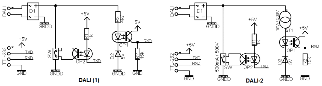
- DALI Interface Circuit: The ESP32’s GPIOs (typically 3.3V logic) cannot directly connect to the DALI bus (which operates at higher voltages and requires specific current driving capabilities). A simple interface circuit is needed. This typically involves:
- Transmission (TX): A transistor (e.g., NPN BJT or N-channel MOSFET) to pull the DALI bus line low, driven by an ESP32 GPIO.
- Reception (RX): An optocoupler or voltage divider/comparator circuit to sense the DALI bus state and feed it back to an ESP32 GPIO.
- Commercially available DALI transceiver ICs (e.g., Microchip ATPL100A, Renesas R2A20134) simplify this but are more complex components. For a basic example, a discrete component interface is often used.
- DALI Bus Power Supply: A DALI-compliant PSU providing ~16V and limited to 250mA.
- DALI Control Gear: A DALI-enabled LED driver or ballast connected to a suitable lamp.
- Wiring: Connect the ESP32 (via the interface circuit), DALI PSU, and DALI control gear to the two-wire DALI bus.
Warning: Ensure your DALI interface circuit is correctly designed to prevent damage to the ESP32 or the DALI bus. Incorrect voltages or lack of current limiting can be harmful. The DALI bus itself is short-circuit protected by the DALI PSU.
Software: Using RMT for DALI
The RMT peripheral can generate sequences of pulses with defined durations. For DALI’s Manchester encoding at 1200 bps, each half-bit (Te) is approximately 416.67 µs.
- RMT Ticker Clock: The RMT peripheral uses a source clock (e.g., APB clock, typically 80MHz). A divisor is used to get a slower RMT “tick.” For DALI, we need to achieve timings in the hundreds of microseconds.
- Example: If APB_CLK is 80MHz,
rmt_config_t::clk_divcan be set to scale this. Ifclk_div = 80, then 1 RMT tick = 1µs. - A half-bit (Te) of ~417µs would then be 417 RMT ticks.
- Example: If APB_CLK is 80MHz,
- Encoding a DALI bit with RMT:
- Logic ‘1’ (Low-to-High transition):
- Level 0 for Te (e.g., 417 ticks).
- Level 1 for Te (e.g., 417 ticks).
- Logic ‘0’ (High-to-Low transition):
- Level 1 for Te (e.g., 417 ticks).
- Level 0 for Te (e.g., 417 ticks).
- Logic ‘1’ (Low-to-High transition):
- Idle State: The DALI bus is idle high.
Code Snippet 1: Sending a DALI Command (Turn ON Light to Short Address 0)
This example demonstrates configuring an RMT channel to send a DALI “ON” command to short address 0. We’ll assume a DALI interface circuit where pulling the ESP32 GPIO low pulls the DALI bus line low.
Project Structure:
esp32_dali_master/
├── CMakeLists.txt
├── main/
│   ├── dali_example_main.c
│   └── CMakeLists.txt
└── sdkconfig       (Generated by menuconfig)
main/CMakeLists.txt:
idf_component_register(SRCS "dali_example_main.c"
                    INCLUDE_DIRS ".")
CMakeLists.txt (Project root):
cmake_minimum_required(VERSION 3.16)
include($ENV{IDF_PATH}/tools/cmake/project.cmake)
project(esp32_dali_master)
main/dali_example_main.c:
#include <stdio.h>
#include "freertos/FreeRTOS.h"
#include "freertos/task.h"
#include "driver/rmt_tx.h"
#include "esp_log.h"
static const char *TAG = "DALI_MASTER";
#define DALI_TX_GPIO_NUM GPIO_NUM_18 // Example GPIO, choose an available one
#define DALI_RMT_CHANNEL RMT_CHANNEL_0 // Deprecated in IDF v5.x, using new API
#define RMT_RESOLUTION_HZ 1000000 // 1MHz resolution, 1 tick = 1µs
#define DALI_HALF_BIT_PERIOD_US 417 // Te = 1 / (1200 * 2) = 416.66 µs, rounded
// DALI Manchester Encoder
// For DALI, idle is high. A '0' pulls the bus low then high. A '1' keeps bus high then pulls low.
// However, if your transistor inverts, then:
// To send '0' (High-Low transition on bus): ESP_GPIO_HIGH -> ESP_GPIO_LOW
// To send '1' (Low-High transition on bus): ESP_GPIO_LOW -> ESP_GPIO_HIGH
// Assuming non-inverting interface for simplicity, or RMT carrier is configured to invert.
// For this example, assuming `level0` pulls DALI low, `level1` lets DALI go high.
static void IRAM_ATTR dali_manchester_encoder(rmt_encoder_t *encoder, rmt_channel_handle_t channel, const void *primary_data, size_t data_size, rmt_encode_state_t *ret_state) {
rmt_dali_manchester_encoder_t *dali_encoder = __containerof(encoder, rmt_dali_manchester_encoder_t, base);
rmt_encoder_handle_t bytes_encoder = dali_encoder->bytes_encoder;
rmt_encode_state_t session_state = RMT_ENCODE_STATE_INIT;
int encoded_symbols = 0;
const uint8_t *data = (const uint8_t *)primary_data;
// This is a simplified custom encoder. ESP-IDF v5.x has built-in bytes_encoder and copy_encoder.
// We need to construct RMT symbols for Manchester encoding.
// Each DALI bit becomes two RMT symbols.
rmt_symbol_word_t dali_symbols[DALI_FRAME_MAX_SYMBOLS]; // Define this based on max frame bits
int symbol_idx = 0;
// Start Bit (always 1)
dali_symbols[symbol_idx++] = (rmt_symbol_word_t){.level0 = 0, .duration0 = DALI_HALF_BIT_PERIOD_US, .level1 = 1, .duration1 = DALI_HALF_BIT_PERIOD_US};
for (size_t i = 0; i < data_size; i++) {
for (int bit = 7; bit >= 0; bit--) {
if ((data[i] >> bit) & 0x01) { // DALI '1' (Low-High on bus if level0=LOW, level1=HIGH for RMT)
dali_symbols[symbol_idx++] = (rmt_symbol_word_t){.level0 = 0, .duration0 = DALI_HALF_BIT_PERIOD_US, .level1 = 1, .duration1 = DALI_HALF_BIT_PERIOD_US};
} else { // DALI '0' (High-Low on bus)
dali_symbols[symbol_idx++] = (rmt_symbol_word_t){.level0 = 1, .duration0 = DALI_HALF_BIT_PERIOD_US, .level1 = 0, .duration1 = DALI_HALF_BIT_PERIOD_US};
}
}
}
// Stop bits (bus idle high, so effectively two '1's but without transitions, just keep high)
// RMT handles this by returning to idle state. Or send two explicit "high" symbols.
// For simplicity, we rely on RMT idle level being high.
encoded_symbols = rmt_encode(bytes_encoder, channel, dali_symbols, symbol_idx * sizeof(rmt_symbol_word_t), &session_state);
*ret_state = session_state; // Or RMT_ENCODE_STATE_FINISH if all done in one go.
// return encoded_symbols; // Old API style
}
// Structure for our custom DALI encoder (if needed beyond basic symbol construction)
typedef struct {
rmt_encoder_t base;
rmt_encoder_handle_t bytes_encoder; // For encoding raw symbols
// add other members if needed
} rmt_dali_manchester_encoder_t;
// Helper to create RMT symbols for DALI
// Note: ESP-IDF v5.1+ has rmt_new_bytes_encoder and rmt_new_copy_encoder.
// For full Manchester, you often build symbols directly.
static size_t rmt_encode_dali_frame(rmt_symbol_word_t *rmt_items, uint8_t address_byte, uint8_t data_byte) {
size_t num_symbols = 0;
// Start bit (logic '1')
rmt_items[num_symbols++] = (rmt_symbol_word_t){.level0 = 0, .duration0 = DALI_HALF_BIT_PERIOD_US, .level1 = 1, .duration1 = DALI_HALF_BIT_PERIOD_US};
// Address byte
for (int i = 7; i >= 0; i--) {
if ((address_byte >> i) & 0x01) { // Bit is '1'
rmt_items[num_symbols++] = (rmt_symbol_word_t){.level0 = 0, .duration0 = DALI_HALF_BIT_PERIOD_US, .level1 = 1, .duration1 = DALI_HALF_BIT_PERIOD_US};
} else { // Bit is '0'
rmt_items[num_symbols++] = (rmt_symbol_word_t){.level0 = 1, .duration0 = DALI_HALF_BIT_PERIOD_US, .level1 = 0, .duration1 = DALI_HALF_BIT_PERIOD_US};
}
}
// Data byte
for (int i = 7; i >= 0; i--) {
if ((data_byte >> i) & 0x01) { // Bit is '1'
rmt_items[num_symbols++] = (rmt_symbol_word_t){.level0 = 0, .duration0 = DALI_HALF_BIT_PERIOD_US, .level1 = 1, .duration1 = DALI_HALF_BIT_PERIOD_US};
} else { // Bit is '0'
rmt_items[num_symbols++] = (rmt_symbol_word_t){.level0 = 1, .duration0 = DALI_HALF_BIT_PERIOD_US, .level1 = 0, .duration1 = DALI_HALF_BIT_PERIOD_US};
}
}
// Stop bits are implicitly handled by the RMT returning to idle (high) state.
// Or, you can explicitly add them:
// rmt_items[num_symbols++] = (rmt_symbol_word_t){.level0 = 1, .duration0 = DALI_HALF_BIT_PERIOD_US * 2, .level1 = 1, .duration1 = 0}; // Hold high for 1 bit time
// rmt_items[num_symbols++] = (rmt_symbol_word_t){.level0 = 1, .duration0 = DALI_HALF_BIT_PERIOD_US * 2, .level1 = 1, .duration1 = 0}; // Hold high for 1 bit time
return num_symbols;
}
void app_main(void) {
ESP_LOGI(TAG, "Initializing RMT TX for DALI");
rmt_tx_channel_config_t tx_chan_config = {
.gpio_num = DALI_TX_GPIO_NUM,
.clk_src = RMT_CLK_SRC_DEFAULT, // IDF v5.x uses RMT_CLK_SRC_DEFAULT, often APB
.resolution_hz = RMT_RESOLUTION_HZ,
.mem_block_symbols = 64, // Size of memory block in RMT symbols (IDF v5.x style)
.trans_queue_depth = 4, // Depth of transaction queue
.flags.invert_out = false, // DALI bus is idle high. If GPIO output is low active on your interface circuit, set this to true.
// This example assumes level0 = low signal on bus, level1 = high signal on bus.
.flags.io_loop_back = false, // Don't loop back TX to RX for this example
// .flags.io_od_mode = true, // Consider open-drain mode if your hardware requires it
};
rmt_channel_handle_t tx_channel = NULL;
ESP_ERROR_CHECK(rmt_new_tx_channel(&tx_chan_config, &tx_channel));
// DALI uses Manchester encoding. We'll use the "copy_encoder" to send pre-computed symbols.
rmt_encoder_handle_t dali_encoder = NULL;
rmt_copy_encoder_config_t copy_encoder_config = {}; // Empty config for copy encoder
ESP_ERROR_CHECK(rmt_new_copy_encoder(©_encoder_config, &dali_encoder));
ESP_ERROR_CHECK(rmt_enable(tx_channel));
ESP_LOGI(TAG, "RMT TX Initialized and Enabled");
// DALI Frame: Address Byte + Data Byte
// Example: Turn ON Short Address 0
// Short Address 0: Y=0, AAAAAA=000000, S=0 (command) -> 00000000
uint8_t address_byte = 0b00000000; // Short Address 0, Command
// Command: RECALL MAX LEVEL (preferred over ON for DALI-2)
uint8_t data_byte = 0x05; // RECALL MAX LEVEL (0x00 is OFF, 0xFE is DIRECT ARC POWER 254)
// For broadcast ON: address_byte = 0b11111110, data_byte = some ON command
// For DAPC to SA0, value 128: address_byte = 0b00000001, data_byte = 128
rmt_symbol_word_t rmt_items[1 + 8 + 8 + 2]; // Start bit + Addr bits + Data bits + potential Stop bits
size_t num_symbols = rmt_encode_dali_frame(rmt_items, address_byte, data_byte);
rmt_transmit_config_t transmit_config = {
.loop_count = 0, // Send once
// .flags.eot_level = 1 // Level for the RMT channel to stay at after transaction
};
ESP_LOGI(TAG, "Sending DALI frame: ADDR=0x%02X, DATA=0x%02X", address_byte, data_byte);
for(int i=0; i<num_symbols; i++) {
ESP_LOGD(TAG, "Symbol %d: L0 %d dur0 %d, L1 %d dur1 %d", i, rmt_items[i].level0, rmt_items[i].duration0, rmt_items[i].level1, rmt_items[i].duration1);
}
while (1) {
// Send the DALI command
esp_err_t ret = rmt_transmit(tx_channel, dali_encoder, rmt_items, num_symbols * sizeof(rmt_symbol_word_t), &transmit_config);
if (ret == ESP_OK) {
ESP_LOGI(TAG, "DALI Frame sent successfully!");
} else {
ESP_LOGE(TAG, "Failed to send DALI Frame: %s", esp_err_to_name(ret));
}
// Wait for RMT to finish transmission. Important!
rmt_tx_wait_all_done(tx_channel, pdMS_TO_TICKS(1000)); // Timeout 1 sec
vTaskDelay(pdMS_TO_TICKS(2000)); // Send every 2 seconds
// Example: Send OFF command
data_byte = 0x00; // OFF command
num_symbols = rmt_encode_dali_frame(rmt_items, address_byte, data_byte);
ESP_LOGI(TAG, "Sending DALI frame: ADDR=0x%02X, DATA=0x%02X (OFF)", address_byte, data_byte);
ret = rmt_transmit(tx_channel, dali_encoder, rmt_items, num_symbols * sizeof(rmt_symbol_word_t), &transmit_config);
if (ret == ESP_OK) {
ESP_LOGI(TAG, "DALI Frame sent successfully!");
} else {
ESP_LOGE(TAG, "Failed to send DALI Frame: %s", esp_err_to_name(ret));
}
rmt_tx_wait_all_done(tx_channel, pdMS_TO_TICKS(1000));
vTaskDelay(pdMS_TO_TICKS(2000)); // Send every 2 seconds
}
}
Explanation of dali_example_main.c:
- Includes: Standard headers, FreeRTOS, RMT driver, and logging.
- Definitions:
DALI_TX_GPIO_NUM: The GPIO pin used for DALI transmission.RMT_RESOLUTION_HZ: Sets the RMT tick frequency to 1MHz (1 tick = 1µs).DALI_HALF_BIT_PERIOD_US: Defines Te (417 µs) for DALI’s 1200 bps rate.
rmt_encode_dali_frame()Function:- This helper function takes the DALI address and data bytes and constructs an array of
rmt_symbol_word_t. - Each DALI bit (start, address, data) is converted into two RMT symbol entries representing the Low-High or High-Low transition of Manchester encoding.
level0andduration0define the first half of the bit,level1andduration1define the second half.- The DALI bus is idle HIGH. To send a ‘1’ (Low-High transition), the RMT first drives the line LOW then HIGH. To send a ‘0’ (High-Low transition), it drives HIGH then LOW. This assumes your DALI interface circuit is non-inverting or the
invert_outflag is set appropriately.
- This helper function takes the DALI address and data bytes and constructs an array of
app_main()Function:- RMT TX Channel Configuration (
rmt_tx_channel_config_t):- Sets the GPIO, clock source, resolution (1MHz), memory block size, and transaction queue depth.
flags.invert_out: Set this based on your hardware interface. If your transistor inverts the ESP32 signal (GPIO LOW = DALI Bus LOW), theninvert_outmight befalseiflevel0means GPIO LOW. If GPIO LOW = DALI Bus HIGH, theninvert_outmight betrue. Test this carefully. This example assumeslevel0inrmt_symbol_word_tcorresponds to the DALI bus being pulled LOW by the interface.
- RMT Channel Creation (
rmt_new_tx_channel()): Allocates and initializes a new RMT transmit channel. - RMT Encoder Creation (
rmt_new_copy_encoder()): For this example, we are pre-calculating the RMT symbols. Thecopy_encodersimply copies these symbols to the RMT hardware. - Enable RMT Channel (
rmt_enable()): Starts the RMT channel. - DALI Frame Construction:
address_byte:0b00000000for short address 0, command type.data_byte:0x05forRECALL MAX LEVEL. (DALI command to turn light on to its configured max).- Calls
rmt_encode_dali_frame()to populate thermt_itemsarray.
- Transmission Configuration (
rmt_transmit_config_t):loop_count = 0: Send the sequence only once perrmt_transmitcall.
- Transmit Loop:
- Calls
rmt_transmit()to send the prepared DALI symbols. rmt_tx_wait_all_done(): Crucial step. Waits until the RMT hardware has finished sending all symbols. Without this, you might try to send another command too quickly.- Alternates between sending ON and OFF commands every 2 seconds.
- Calls
- RMT TX Channel Configuration (
Code Snippet 2: Receiving a DALI Response (Conceptual)
Receiving DALI responses involves configuring an RMT RX channel to capture Manchester encoded signals. This is more complex due to:
- Timing Precision: The receiver must accurately measure pulse widths.
- Collision Detection: If multiple slaves respond, the signal will be corrupted.
- Decoding: Converting the received RMT symbols back into DALI bytes.
Conceptual Steps for RMT RX for DALI:
- Configure RMT RX Channel:
- Set GPIO for DALI RX.
- Set resolution (e.g., 1MHz).
- Define filter thresholds to ignore noise (
filter_ticks_thresh). - Set idle threshold (
idle_threshold) to detect the end of a frame.
- Start RMT Receiver:
rmt_receive(). - Process Received Data:
- The RMT driver will provide an array of
rmt_symbol_word_trepresenting the captured pulses. - Iterate through the symbols, pair them up, and decode Manchester bits:
- Low pulse followed by High pulse of ~Te duration = DALI ‘1’.
- High pulse followed by Low pulse of ~Te duration = DALI ‘0’.
- Validate start bit, frame length, and (potentially) stop bits.
- Assemble the data byte.
- The RMT driver will provide an array of
Tip: Implementing a robust DALI RX, including collision detection and proper state machine for the DALI protocol, is a significant task. For many applications, sending commands (master TX) is the primary requirement. ESP-IDF provides examples for generic RMT RX that can be adapted.
Build Instructions (VS Code with ESP-IDF Extension)
- Open Project: Open the
esp32_dali_masterfolder in VS Code. - Set Target: Use the ESP-IDF extension to set your ESP32 variant (e.g., ESP32, ESP32-S3).
- SDKCONFIG Defaults: If you have specific hardware (like a custom DALI interface that needs open-drain or inverted output), you might need to adjust
sdkconfigdefaults or the RMT configuration flags in the code. - Build: Click the “Build” button in the VS Code status bar (or run
idf.py buildin the ESP-IDF terminal). - Flash: Connect your ESP32 board. Click the “Flash” button (or run
idf.py -p (PORT) flash). - Monitor: Click the “Monitor” button (or run
idf.py -p (PORT) monitor) to seeESP_LOGImessages.
Run/Flash/Observe Steps
- Ensure your DALI hardware is correctly set up: ESP32 with interface circuit, DALI PSU, and DALI control gear all connected to the DALI bus.
- Power on the DALI PSU.
- Power on the ESP32 board (usually via USB after flashing).
- Observe the DALI lamp. It should turn ON (to its max configured level) and OFF every 2 seconds, corresponding to the DALI commands being sent.
- Check the serial monitor output for log messages confirming successful transmission.
Variant Notes
The DALI implementation method described using the RMT peripheral is broadly applicable to most ESP32 variants that include the RMT module.
- ESP32, ESP32-S2, ESP32-S3, ESP32-C3, ESP32-C6, ESP32-H2: All these variants feature the RMT peripheral. The number of RMT channels and specific capabilities (like the maximum number of symbols in a memory block) might vary slightly, but the fundamental approach of using RMT for generating timed pulses for Manchester encoding remains the same.
- RMT Channels: ESP32 has 8 TX and 8 RX channels. ESP32-S2/S3 typically have 4 TX and 4 RX. ESP32-C3 has 2 TX and 2 RX. ESP32-C6 and H2 also have RMT channels (check datasheets for exact numbers). Ensure you select an available channel.
- GPIOs: Any GPIO capable of digital output can be used for DALI TX, and any GPIO capable of digital input for DALI RX. Refer to the datasheet for your specific ESP32 variant to choose appropriate pins and avoid conflicts with other peripherals (e.g., strapping pins, JTAG).
- RMT API Versions: The code example uses the ESP-IDF v5.x RMT driver API (
rmt_new_tx_channel,rmt_new_copy_encoder, etc.). Earlier IDF versions had a different RMT API (rmt_config,rmt_driver_install). Ensure your project and IDF version are aligned. - Performance: Generating DALI’s 1200 bps signal is not demanding for ESP32 processors. The RMT peripheral handles the precise timing offloading the CPU.
- No Native DALI Peripheral: It’s important to reiterate that ESP32 microcontrollers do not have a dedicated hardware DALI peripheral. The implementation relies on using general-purpose peripherals like RMT (or bit-banging GPIOs, which is less reliable for precise timing).
Common Mistakes & Troubleshooting Tips
| Mistake / Issue | Symptom(s) | Troubleshooting / Solution |
|---|---|---|
| Missing or Faulty DALI PSU | No communication at all. DALI bus voltage is 0V or unstable. DALI devices are unresponsive. |
1. Verify Connection: Ensure the DALI PSU is correctly wired to the bus. 2. Measure Voltage: Use a multimeter to check the DALI bus voltage. It should be stable at ~16V DC. 3. Check PSU Status: Ensure the PSU itself is powered and its indicator lights (if any) are on. |
| Incorrect Interface Circuit | Commands have no effect. Oscilloscope shows weak, malformed, or inverted signals on the bus. ESP32 may get damaged. |
1. Check Schematic: Double-check your transistor/optocoupler wiring against the reference diagram. 2. Probe the Bus: Use an oscilloscope to observe the waveform. It should swing clearly between ~0V and ~16V. 3. Check RMT Logic: If the signal is inverted, toggle the flags.invert_out setting in your RMT configuration. |
| RMT Timing Errors | Intermittent or no response from DALI gear. Devices may flicker or behave erratically. |
1. Verify Constants: Ensure DALI_HALF_BIT_PERIOD_US is ~417 and RMT_RESOLUTION_HZ is 1,000,000 for 1µs precision. 2. Verify Bit Times: Use an oscilloscope to measure the duration of one bit on the DALI bus. It must be ~833µs. |
| Incorrect DALI Frame | Commands are ignored. The target device does not respond as expected, even if other devices do. |
1. Check Address Byte: Verify the YAAAAAAS format. Short address 5 is 00001010, not just the number 5. 2. Validate Command Code: Ensure the data byte corresponds to a valid DALI command. 3. Use a DALI Analyzer: If available, a DALI protocol analyzer is the best tool to inspect the exact frames being sent. |
| Missing rmt_tx_wait_all_done | The first command works, but subsequent commands fail or are corrupted. Log shows errors about transaction queue overflow. | Always call rmt_tx_wait_all_done(channel, timeout) after every rmt_transmit() call to ensure the hardware is free before sending the next command. |
Exercises
- Direct Arc Power Control:
- Modify the
dali_example_main.cto send aDIRECT ARC POWER (DAPC)command. - The address byte selector bit
Sshould be1for DAPC when addressing a short address (e.g.,YAAAAAA1). The DAPC command itself is implicit when S=1; the data byte contains the power level (0-254). - Allow the user to input a short address and a power level (0-254) via the serial monitor (using
uart_read_bytesor a simple console component) and send the corresponding DAPC command.
- Modify the
- Broadcast OFF Command:
- Change the DALI address byte to send a broadcast “OFF” command to all connected devices. The broadcast address for commands is typically
11111110(Y=1, AAAAAA=111111, S=0). The data byte for “OFF” is0x00.
- Change the DALI address byte to send a broadcast “OFF” command to all connected devices. The broadcast address for commands is typically
- Simple DALI Scanner (Query Control Gear):
- Implement a function that iterates through all possible short addresses (0 to 63).
- For each address, send a
QUERY CONTROL GEARcommand (Data Byte:0x99). The address byte should be0AAAAAA1(S=1 for query). - To detect a response, you would ideally need DALI RX functionality. As a simpler exercise (without full RX), send the query and assume if a device is present, it might briefly affect the bus (this is not a reliable detection method without RX). For a more advanced version, if you implement basic RX, check for any backward frame. Log the addresses that might be present.
- Dimming Sequence:
- Create a sequence that gradually dims a light up and then down.
- Use
DIRECT ARC POWERcommands in a loop, incrementing/decrementing the power level (e.g., from 50 to 200 and back to 50 in steps of 10). Add a short delay between commands.
- FreeRTOS DALI Control Task:
- (Advanced) Design a FreeRTOS task that manages DALI communication.
- This task should periodically send a
QUERY ACTUAL LEVELcommand (Data Byte:0xA0) to a specific short address. - If you have DALI RX implemented, the task should attempt to read and log the response. If not, simply focus on sending the query periodically. This exercise emphasizes integrating DALI control into a multitasking environment.
Summary
- DALI is a robust, standardized two-wire protocol (IEC 62386) for digital control of lighting equipment, offering individual and group addressing, and bi-directional communication.
- A DALI system comprises a master (controller), control gear (slaves), a two-wire bus, and a DALI bus power supply (PSU).
- Communication uses Manchester encoding at 1200 bps. Forward frames (master to slave) are 19 bits; backward frames (slave to master) are 11 bits.
- Addressing includes short addresses (0-63), group addresses (0-15), and broadcast.
- Commands cover direct power control, scene recall, status queries, and configuration.
- DALI-2 enhances interoperability and standardizes control devices.
- The ESP32’s RMT peripheral is well-suited for generating the precisely timed Manchester-encoded signals required for DALI communication, acting as a DALI master.
- A hardware interface circuit is necessary to connect ESP32 GPIOs to the DALI bus.
- Careful attention to timing, bus voltage levels, and DALI frame structure is crucial for successful implementation.
- Most ESP32 variants (ESP32, S2, S3, C3, C6, H2) support DALI implementation via their RMT peripheral.
Further Reading
- DALI Alliance (DiiA): The official source for DALI technology information, standards, and certification.
- Website: https://www.dali-alliance.org/
- IEC 62386: The international standard for DALI. Documents can be purchased from the IEC website.
- IEC Webstore: https://webstore.iec.ch/ (Search for “IEC 62386”)
- ESP-IDF RMT Driver Documentation: Official Espressif documentation for the Remote Control peripheral.
- ESP-IDF Programming Guide: Check the version corresponding to your ESP-IDF setup (e.g., https://docs.espressif.com/projects/esp-idf/en/v5.1.1/esp32/api-reference/peripherals/rmt.html – adjust link for your IDF version and target chip).
- Application Notes and Articles on DALI: Many manufacturers of lighting control gear and microcontrollers publish application notes on DALI implementation. Searching for “DALI protocol explained” or “DALI implementation microcontroller” can yield useful resources.
