
Chapter 127: Advanced ADC Techniques and Calibration
Chapter Objectives
By the end of this chapter, you will be able to:
- Understand common sources of noise in ADC readings and techniques to mitigate them.
- Implement software-based noise reduction techniques like oversampling and averaging.
- Explain the necessity and principles of ADC calibration.
- Describe the different ADC calibration schemes available in ESP-IDF (eFuse Vref, Two-Point, Line Fitting).
- Configure and use the
esp_adc_calicomponent to obtain calibrated voltage readings. - Understand how ADC characteristics and calibration methods can vary across ESP32 variants.
- Apply calibration to practical ADC applications for improved accuracy.
- Troubleshoot common issues related to ADC calibration and advanced readings.
Introduction
In Chapter 126, we learned the fundamentals of configuring and reading raw values from the Analog-to-Digital Converters (ADCs) on ESP32 microcontrollers. While raw ADC readings provide a proportional measure of the input analog voltage, they are often insufficient for applications requiring precise voltage measurements. This is due to inherent non-linearities in the ADC hardware, variations in the reference voltage, and susceptibility to noise.
This chapter focuses on advanced techniques to enhance the accuracy and reliability of your ADC readings. We will explore methods to reduce noise in analog signals and delve deeply into the ADC calibration features provided by ESP-IDF. By understanding and implementing these techniques, you can transform raw, potentially erratic ADC data into meaningful and accurate voltage measurements, crucial for a wide array of sensor-based applications.
Theory
1. Understanding and Mitigating ADC Noise
Noise is an unavoidable aspect of analog signal measurement. It refers to any unwanted electrical signal that gets superimposed on the desired analog signal, leading to fluctuations and inaccuracies in the digitized ADC output.
Common Sources of Noise:
- Power Supply Noise: Fluctuations or ripple on the 3.3V supply rail (VDD_A) used by the ADC can directly affect the reference voltage and introduce errors.
- Internal SoC Noise: High-frequency digital switching within the ESP32 itself (CPU, Wi-Fi, Bluetooth) can couple noise into the sensitive analog ADC circuitry.
- External Interference: Electromagnetic Interference (EMI) or Radio Frequency Interference (RFI) from nearby devices (motors, radios, power lines) can be picked up by sensor wiring acting as an antenna.
- Poor Grounding: Ground loops or inadequate grounding can introduce noise.
- Sensor Noise: The analog sensor itself might produce some level of inherent noise.
- Quantization Noise: This is an inherent error in the ADC process due to the finite number of discrete steps used to represent a continuous analog signal. It’s related to the ADC’s resolution.
Hardware Noise Reduction Techniques:
While this course focuses on software, it’s good to be aware of hardware best practices:
- Decoupling Capacitors: Place bypass/decoupling capacitors (e.g., 0.1µF ceramic, 10µF electrolytic) close to the ESP32’s VDD_A pin and near analog sensors to filter power supply noise.
- Shielded Cables: Use shielded cables for analog signals, especially over longer distances, and connect the shield to ground at one end.
- Proper PCB Layout: Keep analog traces short, away from high-speed digital lines, and use a solid ground plane.
- Ferrite Beads: Can be used on power lines or signal lines to suppress high-frequency noise.

Software Noise Reduction Techniques:
Even with good hardware design, some noise will persist. Software techniques can further improve signal quality.
- Averaging (Simple Moving Average):This is the most straightforward technique. Multiple ADC readings are taken in quick succession, and their average is calculated. This helps to smooth out random noise.
Average = (Sample1 + Sample2 + ... + SampleN) / NThe more samples (N) you average, the greater the noise reduction, but it also reduces the responsiveness of your measurement to rapid changes in the analog signal and increases processing time.
| Aspect | Description | Considerations |
|---|---|---|
| Concept | Taking multiple ADC readings in quick succession and calculating their arithmetic mean. | Effective against random, high-frequency noise. |
| Formula | Average = (S1 + S2 + ... + SN) / N |
Where Si is an individual sample and N is the total number of samples. |
| Benefit | Smoothes out random fluctuations, providing a more stable and representative reading. | Improves Signal-to-Noise Ratio (SNR). |
| Trade-off: Number of Samples (N) | Higher N: Better noise reduction, more stable output. | Lower N: Faster response to signal changes, less processing overhead. |
| Impact on Responsiveness | Averaging introduces a delay. The system becomes less responsive to rapid changes in the analog signal as N increases. | Choose N based on the expected rate of change of the signal being measured. |
| Processing Time | Increases with the number of samples (N) due to more ADC reads and calculations. | Can be significant in time-critical applications. |
| When to Use | When the input signal is relatively stable or changes slowly, and random noise is a concern. | Common in sensor readings like temperature, light intensity, or battery voltage. |
- Oversampling:Oversampling involves sampling the ADC at a rate much higher than required by the signal’s bandwidth. While it doesn’t directly increase the ADC’s hardware resolution, averaging these oversampled readings can effectively increase the signal-to-noise ratio (SNR) and, to some extent, the effective number of bits (ENOB).For every factor of 4 in oversampling, you can theoretically gain 1 bit of additional resolution (up to a certain limit imposed by other noise sources). For example, taking 16 samples and averaging them can potentially improve the resolution by log2(√16) = log2(4) = 2 bits.Tip: Oversampling is most effective against random, uncorrelated noise.
| Aspect | Description | Details & Benefits |
|---|---|---|
| Concept | Sampling the ADC at a rate much higher than the Nyquist frequency of the input signal, then averaging these samples. | Primarily aims to improve the Effective Number of Bits (ENOB) and Signal-to-Noise Ratio (SNR). |
| Mechanism | Averaging multiple oversampled readings helps to reduce random noise (especially quantization noise). The noise tends to average out, while the signal component is reinforced. | Effective against uncorrelated, random noise. |
| Increased Resolution (Theoretical) | For every factor of 4 in oversampling (i.e., taking 4M samples), you can theoretically gain M additional bits of resolution. | Example: Taking 16 samples (42) and averaging can potentially improve resolution by log2(√16) = log2(4) = 2 bits. |
| Signal-to-Noise Ratio (SNR) Improvement | Oversampling and averaging reduces the noise floor, thereby increasing the SNR. | SNR improves by 3dB for every doubling of the number of samples averaged (factor of 2 in oversampling, if noise is white). |
| Requirements | The ADC must be capable of sampling significantly faster than the signal’s bandwidth. | Sufficient processing power to handle the higher sampling rate and averaging calculations. |
| Limitations | The improvement in resolution is limited by other noise sources (e.g., power supply noise, internal SoC noise) and the ADC’s inherent linearity. | Doesn’t improve issues like ADC non-linearity (DNL/INL) directly; calibration is needed for that. |
| Difference from Simple Averaging | While both involve averaging, oversampling specifically refers to sampling much faster than needed for the signal bandwidth with the goal of increasing effective resolution. Simple averaging might be done at lower rates just to smooth noise. | The theoretical gain in bits is a key characteristic of oversampling. |
- Digital Filtering (e.g., Low-Pass Filter):More complex digital filters (like FIR or IIR filters) can be implemented in software to selectively remove noise at specific frequencies. For example, a low-pass filter can remove high-frequency noise while allowing slower-changing DC or low-frequency signals from sensors to pass through. This is a more advanced topic, often requiring signal processing knowledge.
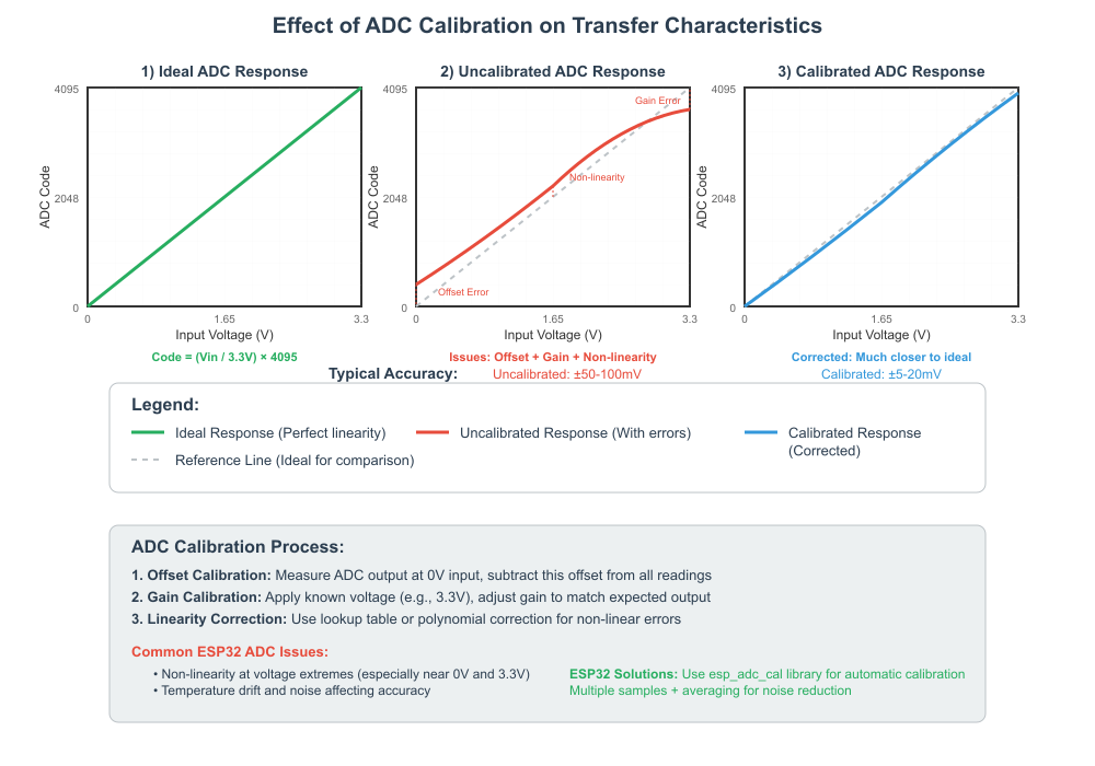
2. ADC Calibration Principles
The raw digital values read from an ESP32’s ADC do not directly and linearly map to the input voltage across all chips and conditions. This is due to:
- Reference Voltage (Vref) Variation: The internal reference voltage used by the ADC can vary slightly from chip to chip and can also be affected by temperature and power supply fluctuations.
- Non-Linearity: ADCs are not perfectly linear. The relationship between the input analog voltage and the output digital code might deviate from a straight line. This deviation is characterized by Differential Non-Linearity (DNL) and Integral Non-Linearity (INL) errors.
ADC calibration is the process of characterizing these errors and applying corrections to the raw ADC readings to obtain more accurate voltage measurements. ESP-IDF provides the esp_adc_cali component to facilitate this.
ESP-IDF ADC Calibration Schemes:
The esp_adc_cali component supports different calibration schemes, depending on the ESP32 variant and the data available in its eFuses (one-time programmable memory).
- eFuse Vref Calibration:
- Some ESP32 variants (like the original ESP32) store an individually measured ADC reference voltage (Vref) value in their eFuses during factory testing.
- If this eFuse Vref is available and valid, the
esp_adc_calicomponent can use it as a more accurate reference voltage than the nominal default (typically around 1100mV). - This is a single-point calibration, primarily correcting for Vref deviations. It assumes a linear ADC response.
- Applicability: Primarily ESP32. Other variants might not have this specific eFuse Vref or might use different calibration data.
- Two-Point Calibration:
- Some ESP32 variants (e.g., ESP32-S2) may have eFuse values representing ADC readings at two known voltage points.
- This allows the calibration component to calculate a slope and an offset to characterize the ADC response more accurately than a single Vref value.
- This scheme can compensate for both Vref variations and some linear gain/offset errors.
- Applicability: Check ESP-IDF documentation for your specific variant.
- Line Fitting (Look-Up Table – LUT based) Calibration:
- This is the most comprehensive calibration scheme provided by ESP-IDF for newer chips (e.g., ESP32-S3, ESP32-C3, ESP32-C6, ESP32-H2).
- The characteristics of the ADC (attenuation curve) are measured at the factory and stored as coefficients or a look-up table in eFuse.
- The
esp_adc_calicomponent uses these factory-provided values to perform a more sophisticated correction, accounting for non-linearities across the ADC’s input range for a given attenuation. - This generally provides the best accuracy among the available schemes.
- Applicability: Newer ESP32 variants.
If no eFuse calibration data is available or if the selected scheme is not supported for the chip/attenuation/bitwidth combination, the esp_adc_cali component might fall back to using default parameters, which essentially means minimal or no calibration.
| Calibration Scheme | Principle | Correction Type | Primary Applicability (Typical) | Accuracy |
|---|---|---|---|---|
| eFuse Vref Calibration | Uses an individually measured ADC reference voltage (Vref) stored in eFuse during factory testing. | Single-point calibration; primarily corrects for Vref deviations. Assumes linear ADC response. | Original ESP32. Some other variants might have Vref in eFuse but may prefer other schemes if available. | Basic improvement over nominal Vref. Does not correct non-linearity. |
| Two-Point Calibration | Uses eFuse values representing ADC readings at two known voltage points (low and high). | Calculates a slope and offset (linear correction). Compensates for Vref variations and some linear gain/offset errors. | ESP32-S2 and potentially other variants if eFuse data for two points is present. | Better than eFuse Vref alone as it addresses some linear errors. Still assumes linearity between the two points. |
| Line Fitting (LUT-based) Calibration | Uses factory-measured ADC characteristics (attenuation curve coefficients or a Look-Up Table) stored in eFuse. | Multi-point or curve-fitting correction. Accounts for non-linearities across the ADC’s input range for a given attenuation. | Newer chips like ESP32-S3, ESP32-C3, ESP32-C6, ESP32-H2. Preferred method if available. | Generally provides the best accuracy among ESP-IDF schemes by addressing non-linearity. |
| No Calibration / Default Parameters | Occurs if no eFuse calibration data is available, the selected scheme is unsupported, or calibration initialization fails. | Minimal or no correction. Raw ADC values are converted using nominal/default Vref and ideal linear assumptions. | Any chip if calibration data is missing/invalid or initialization fails. | Lowest accuracy; susceptible to Vref variations and all ADC non-linearities. |
3. Using the esp_adc_cali Component
The esp_adc_cali component provides functions to:
- Check Calibration Scheme Availability: Determine which calibration scheme (eFuse Vref, Two-Point, Line Fitting) is supported for a given ADC unit, attenuation, and bitwidth on the current chip.
- Initialize Calibration Handle: If a supported scheme is found, initialize a calibration handle with the characteristics for that scheme.
- Convert Raw ADC Reading to Voltage: Use the calibration handle to convert a raw ADC reading (obtained via
adc_oneshot_read()) into a calibrated voltage value in millivolts (mV).
Key Structures and Functions:
adc_cali_handle_t: An opaque handle to the calibration instance.adc_cali_line_fitting_config_t,adc_cali_two_point_config_t,adc_cali_efuse_vref_config_t: Configuration structures for initializing the respective calibration schemes. Typically, you’ll set theunit_id,atten, andbitwidth.esp_err_t adc_cali_check_scheme(adc_cali_scheme_ver_t *scheme_mask): (Older API style) Checks which schemes are supported.esp_err_t adc_cali_create_scheme_line_fitting(const adc_cali_line_fitting_config_t *config, adc_cali_handle_t *ret_handle): Attempts to create a line-fitting calibration handle.esp_err_t adc_cali_create_scheme_two_point(const adc_cali_two_point_config_t *config, adc_cali_handle_t *ret_handle): Attempts to create a two-point calibration handle.esp_err_t adc_cali_create_scheme_efuse_vref(const adc_cali_efuse_vref_config_t *config, adc_cali_handle_t *ret_handle): Attempts to create an eFuse Vref calibration handle.Note: In ESP-IDF v5.x, the approach is often to try creating a handle for the “best” scheme (e.g., line fitting) and if it fails (e.g.,ESP_ERR_NOT_SUPPORTED), try the next best, and so on.esp_err_t adc_cali_raw_to_voltage(adc_cali_handle_t handle, int raw_value, int *voltage_mv): Converts a raw ADC reading to a calibrated voltage in millivolts.esp_err_t adc_cali_delete_scheme_line_fitting(adc_cali_handle_t handle)(and similar for other schemes): Deinitializes the calibration handle.
The general workflow is:
graph TD
    A[Start: ADC Measurement with Calibration] --> B{"Initialize ADC Unit & Channel <br> (e.g., <code>adc_oneshot_new_unit</code>, <br> <code>adc_oneshot_config_channel</code>)"};
    B --> C{Attempt to Create <br> Calibration Handle};
    C --> C1["Try Line Fitting Scheme <br> (<code>adc_cali_create_scheme_line_fitting</code>)"];
    C1 --> D{Successful?};
    D -- No (Error or Not Supported) --> E["Try Two-Point Scheme <br> (<code>adc_cali_create_scheme_two_point</code>)"];
    E --> F{Successful?};
    F -- No (Error or Not Supported) --> G["Try eFuse Vref Scheme <br> (<code>adc_cali_create_scheme_efuse_vref</code>)"];
    G --> H{Successful?};

    D -- Yes --> I["Calibration Handle Created <br> (<code>cali_handle</code> is valid)"];
    F -- Yes --> I;
    H -- Yes --> I;

    H -- "No (All schemes failed)" --> J["No Calibration Handle <br> (<code>cali_handle</code> is NULL)"];

    I --> K["Read Raw ADC Value <br> (<code> adc_oneshot_read </code> )"];
    K --> L["Convert Raw to Voltage <br> (<code>adc_cali_raw_to_voltage</code>) <br> using <code>cali_handle</code>"];
    L --> M{Conversion Successful?};
    M -- Yes --> N["Use Calibrated Voltage (mV)"];
    M -- No (Conversion Error) --> O["Handle Conversion Error <br> (e.g., log, use raw value with caution)"];

    J --> P["Read Raw ADC Value <br> (<code>adc_oneshot_read</code>)"];
    P --> Q["Calibration Not Available <br> (Use raw value or <br> nominal/default conversion)"];

    N --> Z[End: Measurement Complete];
    O --> Z;
    Q --> Z;

    %% Styling
    classDef primary fill:#EDE9FE,stroke:#5B21B6,stroke-width:2px,color:#5B21B6;
    classDef success fill:#D1FAE5,stroke:#059669,stroke-width:2px,color:#065F46;
    classDef decision fill:#FEF3C7,stroke:#D97706,stroke-width:1px,color:#92400E;
    classDef process fill:#DBEAFE,stroke:#2563EB,stroke-width:1px,color:#1E40AF;
    classDef error fill:#FEE2E2,stroke:#DC2626,stroke-width:1px,color:#991B1B;

    class A primary;
    class B,C,C1,E,G,K,L,P process;
    class D,F,H,M decision;
    class I,N success;
    class J,O,Q error;
    class Z primary;
- Initialize ADC unit and configure channel using
adc_oneshotdriver (as in Chapter 126). - Attempt to create a calibration handle for the desired ADC unit, attenuation, and bitwidth, trying preferred schemes first.
- If calibration handle creation is successful:a. Read raw ADC value using adc_oneshot_read().b. Convert raw value to millivolts using adc_cali_raw_to_voltage().
- If calibration handle creation fails for all supported schemes, you might have to rely on default (uncustomized) conversions or implement your own calibration.
Practical Examples
Let’s enhance our ADC reading project from Chapter 126 by incorporating oversampling for noise reduction and ADC calibration for accurate voltage conversion.
Prerequisites: Same as Chapter 126, plus an understanding of the previous chapter’s code.
Hardware Setup: Same as Chapter 126 (potentiometer connected to an ADC1 channel).
Example 1: ADC Reading with Oversampling and Calibration
This example demonstrates:
- Reading multiple ADC samples.
- Averaging them (oversampling).
- Checking for and applying ADC calibration to convert the averaged raw value to millivolts.
1. Project Setup:
Use the project from Chapter 126 (adc_reader) or create a new one based on it.
2. Update idf_component.yml (in main directory):
Ensure esp_adc is listed. The calibration component esp_adc_cali is usually part of esp_adc or automatically linked.
yaml dependencies: idf: “>=5.0” esp_adc: “*” # esp_log, freertos are usually core components
3. main/adc_cali_example_main.c:
Replace the content of your main C file with the following:
#include <stdio.h>
#include <stdlib.h>
#include "freertos/FreeRTOS.h"
#include "freertos/task.h"
#include "esp_log.h"
#include "esp_adc/adc_oneshot.h"
#include "esp_adc/adc_cali.h"
#include "esp_adc/adc_cali_scheme.h" // For adc_cali_check_scheme and scheme creation functions
#include "hal/adc_types.h"

// ADC Configuration (same as Chapter 126)
#define ADC_UNIT        ADC_UNIT_1
// Example: GPIO34 on ESP32. CHECK YOUR DATASHEET/BOARD!
// ESP32: ADC1_CHANNEL_6 (GPIO34)
// ESP32-S2/S3: ADC1_CHANNEL_6 (GPIO7)
// ESP32-C3: ADC1_CHANNEL_4 (GPIO4)
// ESP32-C6: ADC1_CHANNEL_4 (GPIO4)
// ESP32-H2: ADC1_CHANNEL_4 (GPIO4)
#define ADC_CHANNEL     ADC_CHANNEL_6
#define ADC_ATTEN       ADC_ATTEN_DB_11
#define ADC_BITWIDTH    ADC_BITWIDTH_DEFAULT // Or ADC_BITWIDTH_12 etc.

// Oversampling Configuration
#define NO_OF_SAMPLES   64  // Number of samples to average

static const char *TAG = "ADC_CALI_EXAMPLE";

static adc_oneshot_unit_handle_t adc1_handle;
static adc_cali_handle_t cali_handle = NULL;
static bool do_calibration = false;

// Function to initialize ADC unit and channel
static void adc_init(void)
{
    adc_oneshot_unit_init_cfg_t init_config1 = {
        .unit_id = ADC_UNIT,
        .ulp_mode = ADC_ULP_MODE_DISABLE,
    };
    ESP_ERROR_CHECK(adc_oneshot_new_unit(&init_config1, &adc1_handle));

    adc_oneshot_chan_cfg_t config = {
        .atten = ADC_ATTEN,
        .bitwidth = ADC_BITWIDTH,
    };
    ESP_ERROR_CHECK(adc_oneshot_config_channel(adc1_handle, ADC_CHANNEL, &config));
    ESP_LOGI(TAG, "ADC1 Channel %d configured", ADC_CHANNEL);
}

// Function to attempt ADC calibration
static bool adc_calibration_init(adc_unit_t unit, adc_atten_t atten, adc_bitwidth_t bitwidth, adc_cali_handle_t *out_handle)
{
    adc_cali_handle_t handle = NULL;
    esp_err_t ret = ESP_FAIL;
    bool calibrated = false;

    ESP_LOGI(TAG, "Attempting calibration for ADC_UNIT_%d, Atten: %d, Bitwidth: %d", unit, atten, bitwidth);

    // Try Line Fitting Calibration
    // Note: For ESP-IDF v5.0 and later, specific scheme creation functions are preferred.
    // adc_cali_check_scheme was used more in older versions to get a mask.
    // Now, we directly try to create schemes.

    adc_cali_line_fitting_config_t cali_config_lf = {
        .unit_id = unit,
        .atten = atten,
        .bitwidth = bitwidth,
        // .default_vref = 0, // Set to 0 to use eFuse Vref if available, or system default.
                            // Only set if you want to force a specific Vref for line fitting
                            // if eFuse Vref is not burned. Check docs for specific chip behavior.
    };
    ret = adc_cali_create_scheme_line_fitting(&cali_config_lf, &handle);
    if (ret == ESP_OK) {
        calibrated = true;
        ESP_LOGI(TAG, "Line Fitting calibration successful.");
    } else {
        ESP_LOGW(TAG, "Line Fitting calibration failed (err: 0x%x), trying Two Point...", ret);
        // Try Two Point Calibration (if Line Fitting failed or not supported)
        adc_cali_two_point_config_t cali_config_tp = {
            .unit_id = unit,
            .atten = atten,
            .bitwidth = bitwidth,
            // .raw_min = 0, // Optional: raw value at known low voltage
            // .raw_max = 0, // Optional: raw value at known high voltage
            // .voltage_min = 0, // Optional: known low voltage in mV
            // .voltage_max = 0, // Optional: known high voltage in mV
        };
        ret = adc_cali_create_scheme_two_point(&cali_config_tp, &handle);
        if (ret == ESP_OK) {
            calibrated = true;
            ESP_LOGI(TAG, "Two Point calibration successful.");
        } else {
            ESP_LOGW(TAG, "Two Point calibration failed (err: 0x%x), trying eFuse Vref...", ret);
            // Try eFuse Vref Calibration (if Two Point failed or not supported)
            adc_cali_efuse_vref_config_t cali_config_ev = {
                .unit_id = unit,
                .atten = atten,
                // Bitwidth is not part of efuse_vref config struct
            };
             // Note: eFuse Vref scheme might not support all bitwidths directly in its config struct.
             // The calibration data is primarily for Vref. The bitwidth is handled by ADC driver.
            if (bitwidth == ADC_BITWIDTH_DEFAULT || bitwidth == ADC_BITWIDTH_12) { // Example check
                ret = adc_cali_create_scheme_efuse_vref(&cali_config_ev, &handle);
                if (ret == ESP_OK) {
                    calibrated = true;
                    ESP_LOGI(TAG, "eFuse Vref calibration successful.");
                } else {
                    ESP_LOGE(TAG, "eFuse Vref calibration failed (err: 0x%x). No calibration scheme applied.", ret);
                }
            } else {
                 ESP_LOGW(TAG, "eFuse Vref calibration not attempted for bitwidth %d.", bitwidth);
            }
        }
    }


    *out_handle = handle;
    if (calibrated) {
        ESP_LOGI(TAG, "Calibration successful. Handle: %p", handle);
    } else {
        ESP_LOGW(TAG, "ADC Calibration failed for all known schemes.");
    }
    return calibrated;
}


void app_main(void)
{
    // Initialize ADC
    adc_init();

    // Attempt to initialize ADC calibration
    do_calibration = adc_calibration_init(ADC_UNIT, ADC_ATTEN, ADC_BITWIDTH, &cali_handle);

    int adc_raw_reading;
    int voltage_mv;
    uint32_t adc_reading_sum = 0;

    while (1) {
        adc_reading_sum = 0;
        for (int i = 0; i < NO_OF_SAMPLES; i++) {
            if (adc_oneshot_read(adc1_handle, ADC_CHANNEL, &adc_raw_reading) == ESP_OK) {
                adc_reading_sum += adc_raw_reading;
            } else {
                // Handle read error, maybe skip this sample or log
                ESP_LOGW(TAG, "ADC read error in oversampling loop");
            }
        }
        adc_raw_reading = adc_reading_sum / NO_OF_SAMPLES; // Averaged raw reading

        ESP_LOGI(TAG, "ADC1 Channel[%d] Raw Avg: %d", ADC_CHANNEL, adc_raw_reading);

        if (do_calibration && cali_handle) {
            esp_err_t cali_ret = adc_cali_raw_to_voltage(cali_handle, adc_raw_reading, &voltage_mv);
            if (cali_ret == ESP_OK) {
                ESP_LOGI(TAG, "Calibrated Voltage: %d mV", voltage_mv);
            } else {
                ESP_LOGE(TAG, "Calibration conversion failed: %s", esp_err_to_name(cali_ret));
                // Fallback or error handling if conversion fails even with a handle
            }
        } else {
            ESP_LOGW(TAG, "Calibration not available, displaying raw avg only.");
            // You could add a rough, uncalibrated voltage estimate here if needed
            // float rough_voltage = (float)adc_raw_reading * 3300.0f / 4095.0f; // Assuming 12-bit, 3.3V VDD_A
            // ESP_LOGI(TAG, "Approx. Uncalibrated Voltage: %.0f mV", rough_voltage);
        }

        vTaskDelay(pdMS_TO_TICKS(1000));
    }

    // Cleanup (not typically reached in this example)
    // if (do_calibration && cali_handle) {
    //     // Determine which delete function to call based on which scheme succeeded.
    //     // This requires more complex logic to track which scheme was successful.
    //     // For simplicity, if using only one type, call its delete function.
    //     // Example for line fitting:
    //     // ESP_ERROR_CHECK(adc_cali_delete_scheme_line_fitting(cali_handle));
    //     ESP_LOGI(TAG, "Calibration scheme de-initialized.");
    // }
    // ESP_ERROR_CHECK(adc_oneshot_del_unit(adc1_handle));
    // ESP_LOGI(TAG, "ADC1 de-initialized");
}
4. Build, Flash, and Observe:
Follow the same build, flash, and monitor steps as in Chapter 126.
You should see output indicating which calibration scheme (if any) was successfully applied, followed by the averaged raw ADC readings and the calibrated voltage in millivolts.
```
I (XXX) ADC_CALI_EXAMPLE: ADC1 Channel 6 configured
I (XXX) ADC_CALI_EXAMPLE: Attempting calibration for ADC_UNIT_1, Atten: 3, Bitwidth: -1
I (XXX) ADC_CALI_EXAMPLE: Line Fitting calibration successful. // Or another scheme
I (XXX) ADC_CALI_EXAMPLE: Calibration successful. Handle: 0x........
...
I (XXX) ADC_CALI_EXAMPLE: ADC1 Channel[6] Raw Avg: 2050
I (XXX) ADC_CALI_EXAMPLE: Calibrated Voltage: 1650 mV
```
Turn the potentiometer. The raw average and calibrated voltage should change. The calibrated voltage should be a more accurate representation of the actual voltage at the potentiometer wiper (e.g., if wiper is at 1.5V, you should see around 1500 mV).

> **Tip:** The `ADC_BITWIDTH_DEFAULT` resolves to the maximum native bitwidth for the ADC unit on the specific chip (e.g., 12-bit for ESP32, 13-bit for ESP32-S2). The calibration component needs to support this combination of unit, attenuation, and bitwidth.
Variant Notes
ADC characteristics and calibration support vary significantly across ESP32 variants:
- ESP32 (Original):
- Often has eFuse Vref burned.
adc_cali_create_scheme_efuse_vref()is commonly used. - Line fitting might not be supported or might rely on generic curves if specific eFuse data for it is absent.
- ADC non-linearity can be more pronounced compared to newer chips.
- Max resolution: 12-bit.
- Often has eFuse Vref burned.
- ESP32-S2:
- May support Two-Point calibration based on eFuse values.
- Line Fitting calibration is generally preferred if supported by eFuse data.
- Max resolution: 13-bit. The
adc_calicomponent must be compatible with this bitwidth.
- ESP32-S3:
- Primarily uses Line Fitting calibration based on factory-stored characteristics in eFuse. This generally provides good accuracy.
- Max resolution: 12-bit.
- ESP32-C3 / ESP32-C6 / ESP32-H2 (RISC-V based):
- These newer chips also typically rely on Line Fitting calibration using factory-provided eFuse data for their ADCs.
- Max resolution: 12-bit.
- The ADC architecture and performance can differ from Xtensa-based chips.
| ESP32 Variant | Typical Max Resolution (ADC) | Commonly Used/Preferred Calibration Scheme(s) | Key ADC/Calibration Notes |
|---|---|---|---|
| ESP32 (Original) | 12-bit | eFuse Vref. Line Fitting might be generic if specific eFuse data is absent. | ADC non-linearity can be more pronounced. eFuse Vref often available. |
| ESP32-S2 | 13-bit | Line Fitting (if eFuse data present), Two-Point. | Calibration component must support 13-bit width. Improved ADC over original ESP32. |
| ESP32-S3 | 12-bit | Line Fitting (primary, based on factory eFuse data). | Generally good accuracy with Line Fitting. |
| ESP32-C3 | 12-bit | Line Fitting (primary, based on factory eFuse data). | RISC-V core. Relies on factory eFuse data for calibration. |
| ESP32-C6 | 12-bit | Line Fitting (primary, based on factory eFuse data). | RISC-V core with 802.15.4 radio. Similar ADC calibration approach to C3. |
| ESP32-H2 | 12-bit | Line Fitting (primary, based on factory eFuse data). | RISC-V core with 802.15.4 radio. Similar ADC calibration approach to C3/C6. |
| Note: Always consult the latest ESP-IDF documentation and specific chip datasheet for the most up-to-date information, as characteristics can evolve. eFuse availability can vary. | |||
General Considerations for All Variants:
- eFuse Availability: The presence and validity of calibration eFuses can vary even between chips of the same variant due to manufacturing processes. Always check the return value of the
adc_cali_create_scheme_*functions. - Supported Combinations: Not all combinations of
adc_unit_t,adc_atten_t, andadc_bitwidth_tmight have corresponding factory calibration data. The documentation or experimentation might be needed to determine supported calibrated configurations. If a specific combination is not factory calibrated,esp_adc_calimight returnESP_ERR_NOT_SUPPORTEDorESP_ERR_INVALID_STATE. - Attenuation Accuracy: Calibration data is specific to each attenuation setting. If you change attenuation, you must re-initialize the calibration handle for the new attenuation.
- Temperature Effects: While calibration compensates for some initial variations, ADC readings can still drift with significant temperature changes. For very high precision applications, temperature compensation might be an additional consideration (a more advanced topic).
Warning: Always consult the latest ESP-IDF documentation and the datasheet for your specific ESP32 variant, as calibration support and ADC characteristics can evolve with silicon revisions and IDF updates.
Common Mistakes & Troubleshooting Tips
| Mistake / Issue | Symptom(s) | Troubleshooting / Solution |
|---|---|---|
| Calibration Handle Not Initialized or Incorrectly Used |
– Crash or Guru Meditation Error when calling adc_cali_raw_to_voltage().– Function returns ESP_ERR_INVALID_ARG.– Voltage readings are nonsensical or always zero. |
Ensure adc_cali_create_scheme_*() was successful and returned a valid (non-NULL) handle.– Check the return value of the creation function. – Store the handle correctly (e.g., in a static variable if used across functions). – If ADC configuration (attenuation, bitwidth, unit) changes, re-initialize the calibration handle for the new settings. |
| Ignoring Return Values of Calibration Functions |
– Assuming calibration succeeded when it actually failed. – Program proceeds with a NULL or invalid handle, leading to later errors.– Unexpectedly uncalibrated or inaccurate readings. |
Always check esp_err_t return codes from all esp_adc_cali and adc_oneshot functions.– Log errors using ESP_LOGE() and esp_err_to_name().– Implement fallback logic if calibration fails (e.g., use raw values with a warning, or a nominal conversion). |
| Mismatch Between ADC Config and Calibration Config |
– Calibration initialization might fail (e.g., ESP_ERR_NOT_SUPPORTED or ESP_ERR_INVALID_ARG).– If it “succeeds” with mismatched parameters, voltage readings will be incorrect for the actual ADC setup. |
Ensure unit_id, atten, and bitwidth are consistent between:1. adc_oneshot_chan_cfg_t used in adc_oneshot_config_channel().2. The adc_cali_*_config_t structure used when creating the calibration handle (e.g., adc_cali_line_fitting_config_t).
|
| Unrealistic Expectations from Calibration |
– Frustration that readings are not “perfectly” accurate to a multimeter. – Expecting calibration to fix all noise issues. |
Understand limitations: – Calibration significantly improves accuracy but doesn’t eliminate all errors (residual non-linearity, noise, temperature effects). – Accuracy is limited by eFuse data quality and ADC’s inherent performance. – For very high precision, consider external ADCs or further system-level characterization. |
Issues with ADC_BITWIDTH_DEFAULT and Calibration |
– Calibration scheme creation fails if ADC_BITWIDTH_DEFAULT resolves to a bitwidth for which no specific factory calibration data exists (e.g., 13-bit on ESP32-S2 if eFuse data is only for 12-bit).– Error like ESP_ERR_NOT_SUPPORTED.
|
Explicitly set a known supported bitwidth (e.g., ADC_BITWIDTH_12) in both adc_oneshot_chan_cfg_t and the calibration configuration structure.– Check ESP-IDF documentation for supported bitwidths for calibration on your specific ESP32 variant and chosen attenuation. |
| Forgetting to Re-initialize Calibration on Attenuation Change | – If ADC channel attenuation is changed dynamically, but the same old calibration handle (initialized for a different attenuation) is used. – Resulting voltage readings will be significantly incorrect. |
Calibration data is specific to each attenuation setting. – If you change attenuation for an ADC channel, you must de-initialize the old calibration handle (if any) and re-initialize a new one with the new attenuation setting. |
| Noisy Power Supply or Grounding |
– Even with software averaging and calibration, readings are unstable or jumpy. – Calibration helps with ADC characteristics but not primarily with external noise on the analog input. |
Review hardware noise reduction techniques: – Add decoupling capacitors (0.1µF, 10µF) near VDD_A and sensor. – Ensure proper grounding; avoid ground loops. – Use shielded cables for analog signals if necessary. – Keep analog traces short and away from digital noise sources on PCB. |
Exercises
- Impact of Oversampling:
- Modify the practical example to allow changing the
NO_OF_SAMPLESdefine (e.g., try 1, 4, 16, 64, 256). - Observe the stability of the raw ADC readings and the calibrated voltage with a constant input (e.g., potentiometer set to a fixed position).
- Observe the responsiveness when you quickly change the potentiometer. Discuss the trade-off between noise reduction and responsiveness.
- Modify the practical example to allow changing the
- Test Different Attenuations with Calibration:
- Modify the example to use a different attenuation setting (e.g.,
ADC_ATTEN_DB_0orADC_ATTEN_DB_6). - Adjust your input voltage source (e.g., use a voltage divider or a variable power supply) to be within the expected input range for that attenuation (refer to datasheet).
- Verify that calibration is attempted and observe the output voltage. Note any changes in calibration success or accuracy.
- Caution: Be careful not to exceed the maximum input voltage for the selected attenuation to avoid damaging the ESP32.
- Modify the example to use a different attenuation setting (e.g.,
- Manual Two-Point Calibration Data (Conceptual):
- This is more of a thought exercise or advanced task if you have precise voltage sources.
- If using a chip where
adc_cali_create_scheme_two_pointis relevant, research how you might provide your ownraw_min,raw_max,voltage_min,voltage_maxvalues inadc_cali_two_point_config_tif eFuse values are not ideal or present. - This would involve applying two known, precise voltages, reading their raw ADC values, and then using these in the config. (This exercise is about understanding the concept; full implementation requires precision equipment).
- Calibration Failure Fallback:
- In the
adc_calibration_initfunction, if alladc_cali_create_scheme_*calls fail (i.e.,calibratedremainsfalse), implement a fallback mechanism inapp_main. - Instead of just logging “Calibration not available,” calculate and print an approximate voltage based on a nominal Vref (e.g., 1100mV for 0dB attenuation, or 3300mV for 11dB attenuation and 12-bit resolution). This provides a rough estimate when full calibration isn’t possible.
- Formula for rough estimate (11dB, 12-bit, 3.3V full scale):
voltage_mV = raw_value * 3300 / 4095.
- In the
Summary
- ADC readings are susceptible to noise from various sources; software techniques like averaging and oversampling can help mitigate this.
- ADC calibration is crucial for converting raw ADC values into accurate voltage measurements by compensating for Vref variations and non-linearities.
- ESP-IDF provides the
esp_adc_calicomponent with different calibration schemes:- Line Fitting: Uses factory-calibrated eFuse data (common on newer chips like ESP32-S3, C3, C6, H2). Generally the most accurate.
- Two-Point: Uses two eFuse points (e.g., ESP32-S2).
- eFuse Vref: Uses a factory-calibrated Vref value from eFuse (e.g., original ESP32).
- The availability and success of calibration schemes depend on the ESP32 variant, eFuse content, and the specific ADC unit, attenuation, and bitwidth configuration.
- The typical workflow involves initializing the ADC, attempting to create a calibration handle for the desired scheme, and then using
adc_cali_raw_to_voltage()for conversion. - Careful error checking and matching ADC configurations with calibration parameters are essential.
Further Reading
- ESP-IDF ADC Calibration Documentation:
- https://docs.espressif.com/projects/esp-idf/en/v5.4/esp32/api-reference/peripherals/adc_cali.html (Replace
esp32with your target variant likeesp32s3,esp32c3, etc., in the URL for variant-specific details).
- https://docs.espressif.com/projects/esp-idf/en/v5.4/esp32/api-reference/peripherals/adc_cali.html (Replace
- ESP-IDF ADC (One-Shot) Driver Documentation: (As a prerequisite)
- Application Note: Minimizing Noise in ADC Readings (Search Espressif website for relevant app notes if available, or general analog design resources).
- Your Specific ESP32 Variant Datasheet: For details on ADC electrical characteristics and eFuse content.
