
Chapter 289: Manufacturing Test Procedures
Chapter Objectives
By the end of this chapter, you will be able to:
- Understand the purpose and critical importance of manufacturing tests.
- Differentiate between development testing, unit testing, and production hardware testing.
- Design and implement a dedicated manufacturing test firmware application.
- Automate hardware validation for core components like flash memory, Wi-Fi, and other peripherals.
- Create a structured communication protocol for a device to report test results to a factory test jig.
- Understand the complete workflow from assembly to flashing the final production firmware.
Introduction
So far, we have developed, provisioned, and prepared a final production firmware image. The last remaining step before a device can be boxed and shipped is to answer one final, crucial question: “Does the hardware actually work?” A microscopic solder bridge, a faulty capacitor, a misaligned antenna, or an incorrect flash chip can all lead to a dead or malfunctioning device. Finding these faults in the hands of a customer is a recipe for returns, bad reviews, and high support costs.
Manufacturing testing is the final quality gate. It is a series of automated checks performed on every single device that rolls off the assembly line to validate its hardware integrity. This chapter will teach you how to build a dedicated test firmware and design a procedure to quickly and reliably verify that the physical device has been assembled correctly and is ready for its final software.
Theory
What is Manufacturing Test?
Manufacturing testing is not about testing your application’s logic; that’s the job of unit and integration tests during development. Manufacturing testing is purely about hardware validation. Its sole purpose is to confirm that all physical components on the Printed Circuit Board (PCB) are present, correctly installed, and functioning within expected parameters.
Think of it as a car inspection. The inspection doesn’t check if the driver knows how to navigate to the grocery store (the application logic). It checks if the engine starts, the brakes work, and the lights turn on (the hardware integrity).
The Test Firmware and the Test Jig
The process revolves around two key elements: a special test firmware and a physical test jig.
- Manufacturing Test Firmware: This is a small, dedicated ESP-IDF application that is flashed onto a device immediately after assembly. It contains no application logic. Its only function is to run a sequence of hardware tests and report the results.
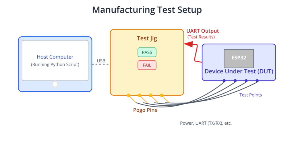
- Test Jig: This is a physical fixture on the factory floor, often custom-designed for the specific product. The Device Under Test (DUT) is placed into the jig, which uses “pogo pins” (spring-loaded contacts) to connect to power, UART, and other test points on the DUT’s PCB. The jig is controlled by a host computer that communicates with the DUT, records the test results, and instructs the factory operator.
%%{ init: { 'theme': 'base', 'themeVariables': { 'fontFamily': 'Open Sans' } } }%%
graph TD
    subgraph "Factory Floor Process"
    A[1- PCB Assembly] --> B{2- Flash Test Firmware};
    B --> C[3- Place DUT in Test Jig];
    C --> D{4- Jig Powers DUT & Runs Test};
    D --> E[5- DUT Reports Results via UART];
    E --> F{6- Host PC Analyzes Results};
    F -->|PASS| H[8- Flash Production Firmware];
    F -->|FAIL| G[7- Send to Rework Station];
    H --> I[9- Final Assembly & Packaging];
    G --> C;
    I --> J[Ship to Customer];
    end

    %% Styling
    classDef startNode fill:#EDE9FE,stroke:#5B21B6,stroke-width:2px,color:#5B21B6;
    classDef processNode fill:#DBEAFE,stroke:#2563EB,stroke-width:1px,color:#1E40AF;
    classDef decisionNode fill:#FEF3C7,stroke:#D97706,stroke-width:1px,color:#92400E;
    classDef failNode fill:#FEE2E2,stroke:#DC2626,stroke-width:1px,color:#991B1B;
    classDef passNode fill:#D1FAE5,stroke:#059669,stroke-width:2px,color:#065F46;

    class A,B,C,D,E,H,I,J processNode;
    class F decisionNode;
    class G failNode;
    class J passNode;
The Test Sequence and Communication
A typical automated test sequence looks like this:
- The test jig powers on the DUT.
- The test firmware on the DUT boots and immediately begins executing its test sequence.
- For each hardware component, it performs a test (e.g., check flash ID, scan for a Wi-Fi AP, read from an I2C sensor).
- After each test, it prints the result over UART in a simple, machine-readable format.
- The host computer connected to the test jig reads this UART output in real-time.
- After all tests are complete, the firmware prints a final
OVERALL_RESULT:PASSorOVERALL_RESULT:FAIL. - The jig’s software parses this output to make a final decision. A “PASS” result might trigger a green light and automatically flash the production firmware, while a “FAIL” triggers a red light and logs the specific test that failed.
| Key | Value Format | Description | Example |
|---|---|---|---|
| TEST_START | String (Test Name) | Marks the beginning of a specific hardware test. | TEST_START:FLASH_ID |
| RESULT | “PASS” or “FAIL” | Indicates the outcome of the test. | RESULT:PASS |
| VALUE | String (Optional) | Provides additional data about the test, like a sensor reading, chip ID, or RSSI value. | VALUE:0x1640ef |
| TEST_END | String (Test Name) | Marks the end of a specific hardware test block. | TEST_END:FLASH_ID |
| OVERALL_RESULT | “PASS” or “FAIL” | The final, conclusive result of the entire test sequence. This is the last line the jig’s software looks for. | OVERALL_RESULT:FAIL |
The key to automation is a structured communication protocol. While you could use complex formats like JSON, a simple key-value format is often faster and sufficient. For example:
TEST_START:FLASH_ID
RESULT:PASS
VALUE:0x123456
TEST_END:FLASH_ID
This is trivial for a script on the host computer to parse and understand.
Practical Examples
Let’s create a manufacturing test firmware for a hypothetical product that has an ESP32, an I2C sensor (at address 0x68), and Wi-Fi.
1. Project Setup
Create a new, standard ESP-IDF project. This project will be our dedicated test firmware. Do not add any of your main application’s components.
2. Designing the Test Functions
We will create a function for each hardware test. Each function will print its results in our structured format and return ESP_OK on success or ESP_FAIL on failure.
main/main.c
#include <stdio.h>
#include <string.h>
#include "freertos/FreeRTOS.h"
#include "freertos/task.h"
#include "esp_log.h"
#include "esp_wifi.h"
#include "nvs_flash.h"
#include "esp_event.h"
#include "spi_flash.h"
#include "driver/i2c.h"

// The MAC address of the I2C sensor we expect to find.
#define I2C_SENSOR_ADDR 0x68
// The SSID of the dedicated test access point in the factory.
#define TEST_AP_SSID "FACTORY_TEST_AP"
// The minimum acceptable signal strength (RSSI) for the Wi-Fi test.
#define WIFI_MIN_RSSI -55

static const char *TAG = "MFG_TEST";

/**
 * @brief Prints the test result in a machine-readable format over UART.
 * * @param test_name The name of the test.
 * @param result ESP_OK for PASS, ESP_FAIL for FAIL.
 * @param value A string containing an optional value (e.g., MAC address, RSSI).
 */
void print_test_result(const char* test_name, esp_err_t result, const char* value) {
    printf("TEST_START:%s\n", test_name);
    printf("RESULT:%s\n", (result == ESP_OK) ? "PASS" : "FAIL");
    if (value) {
        printf("VALUE:%s\n", value);
    }
    printf("TEST_END:%s\n\n", test_name);
    fflush(stdout); // Ensure the output is sent immediately
}

/**
 * @brief Tests the flash chip by reading its ID and verifies the MAC address is valid.
 */
esp_err_t test_flash_and_mac(void) {
    // Test 1: Check flash chip ID
    uint32_t flash_id;
    if (spi_flash_get_chip_id(&flash_id) != ESP_OK) {
        print_test_result("FLASH_ID", ESP_FAIL, "Failed to read ID");
        return ESP_FAIL;
    }
    char flash_id_str[20];
    sprintf(flash_id_str, "0x%x", flash_id);
    print_test_result("FLASH_ID", ESP_OK, flash_id_str);

    // Test 2: Check base MAC address
    uint8_t mac[6];
    if (esp_efuse_mac_get_default(mac) != ESP_OK) {
        print_test_result("MAC_ADDR", ESP_FAIL, "Failed to read MAC");
        return ESP_FAIL;
    }
    char mac_str[18];
    sprintf(mac_str, "%02X:%02X:%02X:%02X:%02X:%02X", mac[0], mac[1], mac[2], mac[3], mac[4], mac[5]);
    print_test_result("MAC_ADDR", ESP_OK, mac_str);

    return ESP_OK;
}

/**
 * @brief Tests the Wi-Fi peripheral by scanning for a factory AP.
 */
esp_err_t test_wifi_scan(void) {
    ESP_ERROR_CHECK(esp_netif_init());
    ESP_ERROR_CHECK(esp_event_loop_create_default());
    esp_netif_t *sta_netif = esp_netif_create_default_wifi_sta();
    assert(sta_netif);

    wifi_init_config_t cfg = WIFI_INIT_CONFIG_DEFAULT();
    ESP_ERROR_CHECK(esp_wifi_init(&cfg));
    ESP_ERROR_CHECK(esp_wifi_set_mode(WIFI_MODE_STA));
    ESP_ERROR_CHECK(esp_wifi_start());

    wifi_scan_config_t scan_config = {
        .ssid = (uint8_t*)TEST_AP_SSID,
        .bssid = 0,
        .channel = 0,
        .show_hidden = true
    };

    esp_err_t err = esp_wifi_scan_start(&scan_config, true);
    if (err != ESP_OK) {
        print_test_result("WIFI_SCAN", ESP_FAIL, "Scan start failed");
        return ESP_FAIL;
    }

    uint16_t num_ap_records = 0;
    esp_wifi_scan_get_ap_num(&num_ap_records);
    if (num_ap_records == 0) {
        print_test_result("WIFI_SCAN", ESP_FAIL, "Test AP not found");
        return ESP_FAIL;
    }

    wifi_ap_record_t ap_records[1];
    ESP_ERROR_CHECK(esp_wifi_scan_get_ap_records(&num_ap_records, ap_records));

    char rssi_str[10];
    sprintf(rssi_str, "%d", ap_records[0].rssi);

    if (ap_records[0].rssi < WIFI_MIN_RSSI) {
        print_test_result("WIFI_RSSI", ESP_FAIL, rssi_str);
        return ESP_FAIL;
    }

    print_test_result("WIFI_RSSI", ESP_OK, rssi_str);
    esp_wifi_stop();
    return ESP_OK;
}

/**
 * @brief Tests the I2C bus by probing for a sensor.
 */
esp_err_t test_i2c_sensor(void) {
    i2c_config_t conf = {
        .mode = I2C_MODE_MASTER,
        .sda_io_num = 21, // Standard I2C pins for many dev boards
        .scl_io_num = 22,
        .sda_pullup_en = GPIO_PULLUP_ENABLE,
        .scl_pullup_en = GPIO_PULLUP_ENABLE,
        .master.clk_speed = 100000,
    };
    i2c_param_config(I2C_NUM_0, &conf);
    i2c_driver_install(I2C_NUM_0, conf.mode, 0, 0, 0);

    // The I2C probe is a simple write command. If it doesn't return an error, a device ACK'd the address.
    i2c_cmd_handle_t cmd = i2c_cmd_link_create();
    i2c_master_start(cmd);
    i2c_master_write_byte(cmd, (I2C_SENSOR_ADDR << 1) | I2C_MASTER_WRITE, true);
    i2c_master_stop(cmd);
    esp_err_t err = i2c_master_cmd_begin(I2C_NUM_0, cmd, pdMS_TO_TICKS(100));
    i2c_cmd_link_delete(cmd);
    i2c_driver_delete(I2C_NUM_0);

    print_test_result("I2C_PROBE", err, (err == ESP_OK) ? "Sensor found" : "Sensor not found");
    return err;
}

void app_main(void)
{
    // It's good practice to initialize NVS, as some drivers might depend on it.
    esp_err_t ret = nvs_flash_init();
    if (ret == ESP_ERR_NVS_NO_FREE_PAGES || ret == ESP_ERR_NVS_NEW_VERSION_FOUND) {
        ESP_ERROR_CHECK(nvs_flash_erase());
        ret = nvs_flash_init();
    }
    ESP_ERROR_CHECK(ret);

    esp_err_t overall_result = ESP_OK;

    if (test_flash_and_mac() != ESP_OK) {
        overall_result = ESP_FAIL;
    }
    vTaskDelay(pdMS_TO_TICKS(100)); // Small delay between tests

    if (test_wifi_scan() != ESP_OK) {
        overall_result = ESP_FAIL;
    }
    vTaskDelay(pdMS_TO_TICKS(100));

    if (test_i2c_sensor() != ESP_OK) {
        overall_result = ESP_FAIL;
    }
    vTaskDelay(pdMS_TO_TICKS(100));

    // Print the final result
    printf("OVERALL_RESULT:%s\n", (overall_result == ESP_OK) ? "PASS" : "FAIL");

    // The test is complete. We can now enter a deep sleep or wait indefinitely.
    printf("---TEST COMPLETE---\n");
    while(1) {
        vTaskDelay(portMAX_DELAY);
    }
}
3. Build and Run the Test
- Connect your device.
- Run
idf.py build flash monitor. - Observe the output in the terminal. It should be clean, structured, and easy to parse:
TEST_START:FLASH_ID
RESULT:PASS
VALUE:0x1640ef
TEST_END:FLASH_ID

TEST_START:MAC_ADDR
RESULT:PASS
VALUE:8C:AA:B5:74:B3:58
TEST_END:MAC_ADDR

TEST_START:WIFI_RSSI
RESULT:FAIL
VALUE:-78
TEST_END:WIFI_RSSI

TEST_START:I2C_PROBE
RESULT:PASS
VALUE:Sensor found
TEST_END:I2C_PROBE

OVERALL_RESULT:FAIL
---TEST COMPLETE---
A test jig’s host software would read this, see the FAIL on WIFI_RSSI and the OVERALL_RESULT, and immediately flag this device for inspection of its antenna connection.
Variant Notes
The fundamental testing strategy is universal, but the specific tests must be tailored to the hardware capabilities of each ESP32 variant.
| ESP32 Variant Family | Key Hardware Feature | Required Manufacturing Test | Test Goal |
|---|---|---|---|
| ESP32, ESP32-S2, ESP32-S3 (e.g., WROVER, S3-WROOM) |
External PSRAM | Write a data pattern to a block of PSRAM, read it back, and verify its integrity using memcmp. | Confirms the PSRAM chip is correctly soldered and all data/address lines are functional. |
| ESP32-S2, ESP32-S3 | USB OTG Peripheral | Initialize the USB driver (e.g., as a CDC device). The test jig’s host PC must verify that the device enumerates correctly. | Validates the USB data lines (D+, D-), the internal PHY, and related components. |
| ESP32-C6, ESP32-H2 | IEEE 802.15.4 Radio (Zigbee/Thread) | Use esp_ieee802154 functions to place the radio in a Continuous Wave (CW) transmission mode. | Allows external RF test equipment in the jig to measure the transmission power and frequency, verifying the 802.15.4 radio and antenna. |
| All Variants | Xtensa vs. RISC-V Core | No change to test methodology. | The ESP-IDF peripheral drivers abstract the core architecture, so test code for peripherals like I2C, SPI, and GPIO remains the same. |
Common Mistakes & Troubleshooting Tips
| Mistake / Issue | Symptom(s) | Troubleshooting / Solution |
|---|---|---|
| Using Production Firmware for Testing | Bloated final firmware size. Test jig logic is complex. Potential for test modes to be accidentally triggered by customers. | Always use a separate, dedicated test firmware. This keeps your production code clean, secure, and optimized. The test firmware is flashed only once at the factory and is then replaced. |
| Using ESP_LOGx for Results | Test jig script fails to parse results. Output is cluttered with timestamps, colors, and log tags (e.g., I (354) MFG_TEST: …). | Use printf() for all results. Define a strict, simple format like KEY:VALUE. This makes parsing on the host PC trivial and reliable. Remember to fflush(stdout). |
| Inadequate RF Testing | Wi-Fi test passes even if the antenna is broken or missing. Customer reports very poor Wi-Fi range. | Test must interact with the physical world. A simple driver init is not enough. Perform a Wi-Fi scan for a dedicated factory AP and check that the RSSI is above a minimum threshold (e.g., -60 dBm). |
| Vague Failure Reports | Jig reports OVERALL_RESULT:FAIL, but the operator doesn’t know why. Rework is slow and involves guesswork. | Report results for each test individually. Include a value where possible. For example, RESULT:FAIL with VALUE:-85 for a Wi-Fi test instantly points to an antenna problem. |
| No Physical Test Points on PCB | It’s impossible to connect the test jig to the DUT. Automated testing of UART, I2C, or power rails cannot be performed. | Plan for testing during hardware design. Expose critical nets (Power, GND, UART TX/RX, I2C SCL/SDA, key GPIOs) as small, accessible pads or vias on the PCB for pogo pins to contact. |
| Wi-Fi Scan Fails Intermittently | The WIFI_SCAN test sometimes passes and sometimes fails with “Test AP not found”, even on good boards. | Ensure proper Wi-Fi initialization and timing. A blocking scan esp_wifi_scan_start(&scan_config, true) is best. Also, ensure the factory environment is not overly congested with 2.4GHz noise. |
Exercises
- GPIO Loopback Test: Design a test function for a board where GPIO 25 is physically wired to GPIO 26. The function,
test_gpio_loopback(), should configure GPIO 25 as an output and GPIO 26 as an input with a pull-down resistor. It should then set GPIO 25 high and check if GPIO 26 reads high. Then, it should set GPIO 25 low and check if GPIO 26 reads low. Report PASS only if both checks succeed. - PSRAM Memory Test: On a board with PSRAM (e.g., an ESP32-WROVER), write a function
test_psram(). It should allocate a small chunk of PSRAM (e.g., 1KB) usingheap_caps_malloc(..., MALLOC_CAP_SPIRAM). Write a known data pattern into this memory, then read it back and usememcmpto verify it’s identical. Report PASS/FAIL and remember to free the memory. - Test Jig Simulator (Python): Write a Python script using the pyserial library that simulates the test jig’s host software. The script should:a. Prompt the user for a COM port.b. Open the serial port and listen for incoming data.c. Read the test output from your ESP32 line-by-line.d. Parse the structured output, printing each test name and its result.e. When it sees the OVERALL_RESULT line, it should print a final summary and exit.
Summary
- Manufacturing tests are performed on every device to validate hardware assembly and functionality.
- Testing is done using a dedicated test firmware and a physical test jig.
- The test firmware’s job is to run a sequence of hardware checks and report results over a communication channel, typically UART.
- Test results must be in a simple, machine-readable format for automated parsing.
- A “PASS” verdict means the hardware is good, and the device can be flashed with the final production firmware. A “FAIL” verdict sends the device for rework.
- Tests should be fast, reliable, and cover all critical hardware components relevant to the specific ESP32 variant.
Further Reading
- ESP-IDF Flash Encryption Guide (related to eFuse and security): https://docs.espressif.com/projects/esp-idf/en/v5.2.1/esp32/security/flash-encryption.html
- Wi-Fi API Reference (for scanning): https://docs.espressif.com/projects/esp-idf/en/v5.2.1/esp32/api-reference/network/esp_wifi.html
- Espressif Production Testing Guide (good overview): https://www.espressif.com/en/solutions/low-power-rtos-sdk/esp-idf/production-testing-guide
