
Chapter 274: Variant-Specific Limitations
Chapter Objectives
By the end of this chapter, you will be able to:
- Identify the key limitations and design trade-offs inherent in each ESP32 variant.
- Understand why certain features are intentionally omitted from cost-sensitive or specialized variants.
- Diagnose and work around common issues, such as the ADC2 and Wi-Fi coexistence problem.
- Analyze the constraints of single-core versus dual-core architectures.
- Read datasheets with a critical eye, looking not just for what a chip has, but also for what it lacks.
- Develop robust engineering practices that account for hardware limitations from the start of a project.
Introduction
In the world of engineering, success is defined not only by leveraging a component’s strengths but also by skillfully navigating its weaknesses. While previous chapters highlighted the powerful and unique peripherals that set ESP32 variants apart, a professional developer must also have a deep understanding of their limitations. Every design choice made by Espressif to optimize a chip for cost, power, or performance results in a trade-off—a feature removed, a resource reduced, or a capability constrained.
Ignoring these limitations can lead to project dead-ends, unstable products, and costly redesigns. Discovering late in development that your chosen chip lacks Bluetooth, has too few pins, or cannot read an analog sensor while Wi-Fi is active can be disastrous. This chapter confronts these constraints head-on. We will treat limitations not as flaws, but as defined design parameters. By understanding them thoroughly, you can make smarter chip selections and build more robust, reliable systems.
Theory: A Catalogue of Constraints
Limitations are not bugs; they are features of the design. A low-cost ESP32-C3 has less RAM and fewer GPIOs precisely because it is optimized for cost. Understanding these trade-offs is key.
1. Core Architecture and Performance Constraints
The CPU core is the heart of the SoC, and its architecture dictates the performance ceiling.
| Specification | ESP32 | ESP32-S2 | ESP32-S3 | ESP32-C3 | ESP32-C6 | ESP32-H2 |
|---|---|---|---|---|---|---|
| CPU Core(s) | Dual-Core LX6 | Single-Core LX7 | Dual-Core LX7 | Single-Core RISC-V | Single-Core RISC-V | Single-Core RISC-V |
| Max CPU Frequency | 240 MHz | 240 MHz | 240 MHz | 160 MHz | 160 MHz | 96 MHz |
| Internal SRAM | 520 KB | 320 KB | 512 KB | 400 KB | 320 KB | 320 KB |
| External PSRAM Support | ✓ | ✗ | ✓ | ✗ | ✗ | ✗ |
- Single-Core vs. Dual-Core:
- Limitation: The ESP32-S2, -C3, -C6, and -H2 are all single-core processors. The original ESP32 and ESP32-S3 are dual-core.
- Implication: On a single-core chip, the application code, the FreeRTOS kernel, and the demanding Wi-Fi/Bluetooth protocol stacks must all share time on the same processor. A computationally intensive application task can potentially “starve” the networking stack, leading to increased latency or connection drops. Conversely, heavy network traffic can make the application logic less responsive.
- Analogy: A dual-core CPU is like having two chefs in a kitchen; one can focus exclusively on preparing the main course (your application) while the other handles all the side dishes and drinks (the network stack). A single-core CPU is a lone chef doing everything, constantly switching between tasks.
- SRAM and Memory Constraints:
- Limitation: The amount of available Static RAM (SRAM) varies dramatically. The C-series and H-series have significantly less SRAM (typically ~320-400 KB) than the S-series or original ESP32 (~520 KB). Furthermore, only the original ESP32 and ESP32-S3 support external PSRAM.
- Implication: Less SRAM imposes a hard limit on application complexity. It restricts the number of tasks you can create, the size of data buffers (for cameras, audio, or large API responses), and the ability to use memory-intensive features like TLS/SSL with large certificate chains. For the C- and H-series, the lack of PSRAM support means there is no option to expand the available memory.
2. Connectivity Limitations
This is one of the most critical areas, as connectivity is the primary purpose of the ESP32 family.
- No Bluetooth at All: The ESP32-S2 is a Wi-Fi-only chip. It has no Bluetooth radio of any kind. This is a deliberate design choice to reduce cost and complexity for products that do not require it.
- No Bluetooth Classic (BR/EDR): Only the original ESP32 supports Bluetooth Classic. All newer variants (S2, S3, C3, C6, H2) support Bluetooth 5 (LE) only. If your application needs to stream audio (A2DP) or use the Serial Port Profile (SPP) for legacy compatibility, the original ESP32 is your only choice.
- No Wi-Fi at All: The ESP32-H2 is designed as a dedicated low-power node for 802.15.4 mesh networks. It has no Wi-Fi radio.
- No Wi-Fi 6: Only the ESP32-C6 (and future variants) supports Wi-Fi 6. All others use Wi-Fi 4 (802.11n).
- No Ethernet MAC: Only the original ESP32 has a built-in Ethernet MAC. For a wired connection on any other variant, you would need a much more complex external SPI-to-Ethernet module (e.g., W5500).
| Feature | ESP32 | ESP32-S2 | ESP32-S3 | ESP32-C3 | ESP32-C6 | ESP32-H2 |
|---|---|---|---|---|---|---|
| Wi-Fi 4 (802.11n) | ✓ | ✓ | ✓ | ✓ | ✓ | ✗ |
| Wi-Fi 6 (802.11ax) | ✗ | ✗ | ✗ | ✗ | ✓ | ✗ |
| Bluetooth LE (BLE) | ✓ | ✗ | ✓ | ✓ | ✓ | ✓ |
| Bluetooth Classic | ✓ | ✗ | ✗ | ✗ | ✗ | ✗ |
| 802.15.4 (Thread/Zigbee) | ✗ | ✗ | ✗ | ✗ | ✓ | ✓ |
| Ethernet MAC | ✓ | ✗ | ✗ | ✗ | ✗ | ✗ |
3. Peripheral and I/O Limitations
The “gotchas” in this section are frequent sources of frustration for new hardware designers.
- The ADC2 and Wi-Fi Conflict:
- Limitation: On all variants that have it, ADC2 cannot be used while the Wi-Fi driver is running.
- Implication: The Wi-Fi radio hardware is internally connected to the same resources as the ADC2 peripheral. When Wi-Fi is active, the radio takes priority, and any attempt to read from a pin assigned to ADC2 will fail. The ESP-IDF
adc2_get_raw()function will return an error code. Pins on ADC1 are not affected and can be used at any time. - Relevance: This is a very common issue. A developer might test their analog sensor on a new board, and it works perfectly. Then, after they initialize Wi-Fi, the sensor readings suddenly stop working.
- GPIO Count and Availability:
- Limitation: Cost-optimized variants have fewer pins. The ESP32-C3 has around 22 GPIOs, while the ESP32-S3 can have up to 45.
- Implication: You must carefully budget your I/O pins on C-series and H-series chips. Furthermore, many pins on a module are not actually available to you. They may be used internally for connecting the flash memory or PSRAM. Always consult the module datasheet, not the SoC datasheet, to see which pins are truly user-accessible.
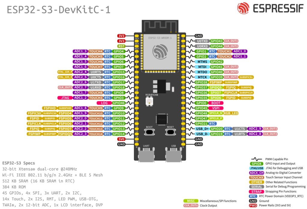
- Strapping Pin Conflicts:
- Limitation: Strapping pins (like GPIO0) are used to set boot modes. While they can often be used as general-purpose I/O after boot, their state during power-on is critical.
- Implication: If you connect a device (like a sensor with a strong pull-down) to a strapping pin that needs to be HIGH at boot, your board will fail to boot correctly. It’s best practice to avoid using critical strapping pins for general I/O unless you can guarantee their state at boot.
sequenceDiagram
    participant User
    participant PowerSupply as "Power Supply"
    participant ESP32
    participant Bootloader

    User->>PowerSupply: Applies Power / Toggles EN pin
    PowerSupply->>ESP32: VCC rises to stable level

    activate ESP32
    Note over ESP32: Chip is held in reset briefly
    ESP32->>ESP32: Reads state of Strapping Pins (GPIO0, etc.)
    Note over ESP32: Decision point based on pin levels
    ESP32->>Bootloader: Jumps to bootloader code in ROM
    deactivate ESP32

    activate Bootloader
    Bootloader->>Bootloader: Reads strapping pin values
    alt Correct Boot Mode <br>(e.g., GPIO0 is HIGH)
        Bootloader->>Bootloader: Configures SPI for Flash
        Bootloader->>Bootloader: Loads application from Flash
        Bootloader->>ESP32: Jumps to app_main()
    else Download Mode <br>(e.g., GPIO0 is LOW)
        Bootloader->>Bootloader: Enters UART download mode
        Note right of Bootloader: Awaits flashing commands.<br>Application does not run.
    end
    deactivate Bootloader
- RTC GPIOs:
- Limitation: Only a subset of GPIOs, known as “RTC GPIOs,” can be used to wake the chip from deep sleep.
- Implication: If you need an external signal (like a button press) to wake your battery-powered device, you must connect that signal to a designated RTC GPIO. The specific RTC-capable pins vary by variant and are listed in the datasheet’s peripherals section.
Practical Examples
Example 1: Working Around the ADC2 / Wi-Fi Conflict
This code demonstrates the correct way to read from an ADC2 pin by controlling access based on the Wi-Fi state. In a real application, you might temporarily stop Wi-Fi, take a burst of readings, and then restart it.
graph TD
    subgraph "Application Logic"
        A[Start ADC Read Task] --> B{Attempt to read from ADC2 pin};
        B --> C{Is Wi-Fi Driver Active?};
        C -- No --> D[Read is Successful];
        D --> E[Process Sensor Value];
        E --> B;
        C -- Yes --> F[Read Fails with ESP_ERR_TIMEOUT];
        F --> G{Need to read sensor now?};
        G -- No --> H["Log warning: 'ADC2 busy'<br>Continue other tasks"];
        H --> B;
        G -- Yes --> I["Temporarily stop Wi-Fi<br><b>(Requires careful state management)</b>"];
        I --> J[Perform burst of ADC2 readings];
        J --> K[Restart Wi-Fi];
        K --> B;
    end

    classDef primary fill:#EDE9FE,stroke:#5B21B6,stroke-width:2px,color:#5B21B6;
    classDef success fill:#D1FAE5,stroke:#059669,stroke-width:2px,color:#065F46;
    classDef decision fill:#FEF3C7,stroke:#D97706,stroke-width:1px,color:#92400E;
    classDef process fill:#DBEAFE,stroke:#2563EB,stroke-width:1px,color:#1E40AF;
    classDef check fill:#FEE2E2,stroke:#DC2626,stroke-width:1px,color:#991B1B;

    class A primary;
    class B,E,H,I,J,K process;
    class C,G decision;
    class D success;
    class F check;
#include "freertos/FreeRTOS.h"
#include "freertos/task.h"
#include "driver/adc.h"
#include "esp_wifi.h"
#include "esp_log.h"

#define ADC2_CHANNEL ADC2_CHANNEL_6 // GPIO27 on many dev boards

static const char *TAG = "ADC_WIFI_EXAMPLE";

// A global flag to indicate if Wi-Fi is active.
// In a real app, this would be managed by your Wi-Fi event handler.
static bool g_wifi_is_active = false;

void wifi_init_task(void *param) {
    // --- Assume Wi-Fi is initialized and started here ---
    // esp_wifi_init(...);
    // esp_wifi_start(...);
    g_wifi_is_active = true;
    ESP_LOGI(TAG, "Wi-Fi has been started.");
    vTaskDelete(NULL);
}


void read_adc_task(void *param) {
    // Configure ADC2
    adc2_config_channel_atten(ADC2_CHANNEL, ADC_ATTEN_DB_11);

    while (1) {
        int raw_value;
        esp_err_t ret = adc2_get_raw(ADC2_CHANNEL, ADC_WIDTH_BIT_12, &raw_value);

        if (ret == ESP_OK) {
            ESP_LOGI(TAG, "ADC2 Read OK: %d", raw_value);
        } else if (ret == ESP_ERR_TIMEOUT) {
            // This is the expected error when Wi-Fi is running.
            ESP_LOGW(TAG, "ADC2 Read Failed: The controller is in use by Wi-Fi.");
        } else {
            ESP_LOGE(TAG, "ADC2 Read Error: %s", esp_err_to_name(ret));
        }

        vTaskDelay(pdMS_TO_TICKS(1000));
    }
}

void app_main(void)
{
    xTaskCreate(read_adc_task, "read_adc_task", 2048, NULL, 5, NULL);

    // After 5 seconds, simulate turning Wi-Fi on.
    vTaskDelay(pdMS_TO_TICKS(5000));
    xTaskCreate(wifi_init_task, "wifi_init_task", 4096, NULL, 5, NULL);
}
Observe: For the first 5 seconds, the ADC readings will succeed. After the wifi_init_task runs and sets the flag, the adc2_get_raw function will start returning ESP_ERR_TIMEOUT, and the log message will change, correctly identifying the conflict.
Common Mistakes & Troubleshooting Tips
| Mistake / Issue | Symptom(s) | Troubleshooting / Solution |
|---|---|---|
| Choosing ESP32-S2 for a Bluetooth project. | Compilation fails. Errors like “esp_bt.h: No such file or directory”. The toolchain cannot find Bluetooth libraries for the S2 target. | This is a hardware limitation with no software fix. You must change your hardware to a variant with a Bluetooth radio, such as the ESP32-S3, ESP32-C3, or the original ESP32. |
| Analog sensor on an ADC2 pin stops working. | Readings are stable initially, but after esp_wifi_start() is called, the ADC function adc2_get_raw() consistently returns ESP_ERR_TIMEOUT. |
The ADC2 peripheral is disabled when Wi-Fi is active. 1. (Best) Move the sensor to a pin on ADC1. 2. (Complex) If you must use ADC2, implement logic to temporarily stop Wi-Fi, take readings, and then restart Wi-Fi. |
| Running out of GPIO pins on a compact variant. | During PCB layout or feature creep, you discover there are no more user-available pins for a required component (e.g., a status LED or button). | 1. (External Hardware) Use a GPIO expander IC like the PCF8574 (I2C) or 74HC595 (SPI) to get more I/O pins. 2. (Redesign) Re-evaluate the project hardware and select a variant with more pins, like moving from an ESP32-C3 to an ESP32-S3. |
| Application crashes due to low memory on ESP32-C3. | The application runs perfectly on a dev kit with an ESP32-S3, but crashes on the production ESP32-C3. Logs show malloc failures or task creation errors. |
The ESP32-C3 has significantly less SRAM and no PSRAM support. You must optimize: reduce task stack sizes, minimize buffer allocations, use const for static data, and analyze memory usage with IDF tools. If optimization is not enough, a higher-spec chip is required. |
| Board won’t boot or enters download mode unexpectedly. | The device is unresponsive after a power cycle, or the serial monitor shows the bootloader waiting for download commands instead of running the application. | This is a classic strapping pin conflict. Check if you have connected anything to critical pins like GPIO0, GPIO2, or GPIO46 that pulls them to a state unintended for boot. Disconnect the peripheral and see if the board boots. If so, move the peripheral to a non-strapping pin. |
Exercises
- The Silent Failure: A developer builds a custom keyboard using an ESP32-S2. They use
GPIO15to read a key matrix column. The keyboard works intermittently, often failing to boot up correctly after a power cycle. Looking at the ESP32-S2 datasheet, what is the likely cause of this problem? (Hint: Check the strapping pins table). - Constraint-Driven Redesign: Your team has a successful product based on the original ESP32 that uses its Ethernet port for industrial control. The marketing department wants a new version that is also compatible with modern smart home systems using the Thread protocol. Can you meet this requirement by simply swapping the original ESP32 for an ESP32-C6? Explain the limitation that prevents this, and propose a two-chip solution.
Summary
- Limitations are by Design: Constraints like reduced RAM or fewer peripherals are intentional choices to optimize for cost or power.
- Know Your Connectivity: The biggest differentiators are the presence or absence of Wi-Fi, Bluetooth Classic, and the 802.15.4 radio. Choosing the wrong chip for your connectivity needs is a project-killing mistake.
- The ADC2/Wi-Fi Conflict is Real: Be aware that you cannot use ADC2 and Wi-Fi simultaneously. Plan your hardware and software around this.
- Single-Core Requires Careful Design: On single-core chips, you must balance the needs of your application and the network stack to ensure both remain responsive.
- Memory is Finite: Cost-optimized chips have limited SRAM and no PSRAM support. Profile your memory usage carefully and choose a chip that provides adequate headroom.
- Read the Datasheet’s Fine Print: Pay close attention to strapping pins, RTC GPIOs, and which pins are reserved for internal module functions.
Further Reading
- ESP32 Technical Reference Manual (TRM): The definitive document for the original ESP32’s architecture, including detailed chapters on each peripheral and their interactions.
- ESP32-S2 Datasheet: A good example to study for its unique combination of a powerful single core and native USB, but lack of Bluetooth.
- ESP-IDF Documentation – ADC Continuous Mode: While the example used single-shot mode, the official docs cover different ADC modes and their constraints.
