
Chapter 259: USB Interface on ESP32-S2/S3
Chapter Objectives
By the end of this chapter, you will be able to:
- Understand the concept of USB On-The-Go (OTG) and its implementation in the ESP32-S2 and S3.
- Differentiate between the native USB interface and a USB-to-UART bridge.
- Configure an ESP32-S3 project to use the native USB for console output (CDC).
- Initialize the USB driver stack (TinyUSB) in an application.
- Understand the basic principles of different USB device classes like CDC, HID, and MSC.
- Troubleshoot common issues related to native USB connectivity and PC drivers.
Introduction
For most of your journey with the ESP32 family, your interaction with the device has likely been through a USB cable connected to a USB-to-UART bridge chip (like a CP210x or CH340) on your development board. This bridge translates serial data, allowing you to program the chip and view logs. However, this is an indirect connection.
The ESP32-S2 and ESP32-S3 variants introduce a game-changing feature: a built-in, native USB On-The-Go (OTG) peripheral. This allows these chips to communicate directly with a host computer over USB without any intermediate bridge. This opens up a world of possibilities: your ESP32 can now act as a keyboard, a mouse, a USB flash drive, a MIDI device, or simply a much faster serial port. This single-cable solution for power, programming, and communication simplifies hardware design and enables a whole new class of powerful applications.
This chapter will guide you through the theory and practical application of this powerful native USB interface.
Theory
1. What is USB On-The-Go (OTG)?
Universal Serial Bus (USB) traditionally defines two roles: the Host (e.g., a PC) and the Device (or Peripheral, e.g., a keyboard). The host controls the bus, initiates communication, and provides power. The device responds to the host’s requests.
USB On-The-Go (OTG) is a specification that allows a single port to act as either a host or a device. An ESP32-S3 with OTG can:
- Act as a Device when plugged into a PC, appearing as a serial port or a mouse.
- Act as a Host to control other USB peripherals, such as a USB flash drive or a keyboard.
The role is typically determined by the type of cable used and software configuration. For most of this chapter, we will focus on the Device role, as it is the most common use case.
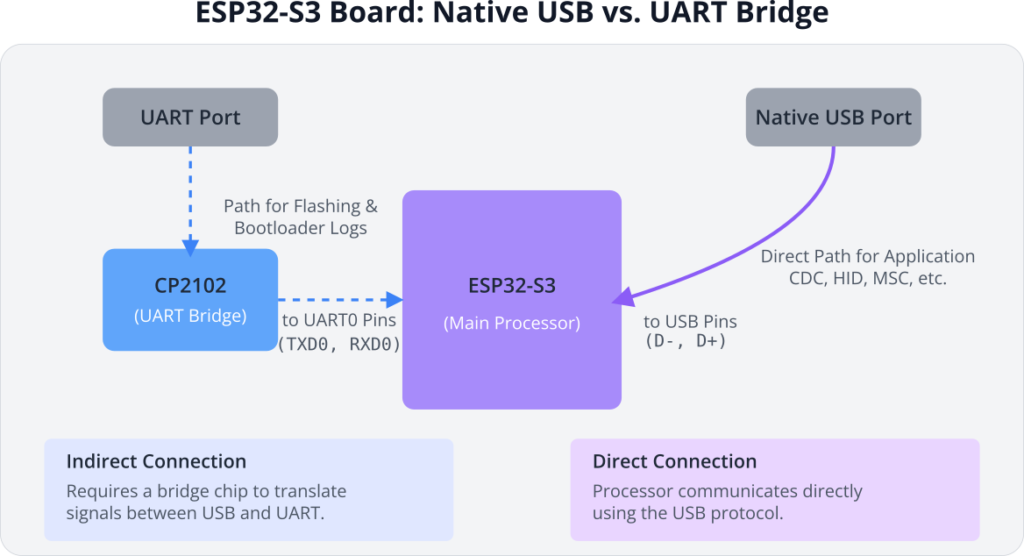
2. Native USB vs. USB-to-UART Bridge
It is critical to understand the two distinct USB ports that may be on your development board.
- UART Port: This port connects to an external USB-to-UART bridge chip, which is then connected to the ESP32’s
UART0pins (TXD0,RXD0). This is used for bootloader output and for programming the chip viaesptool.py. - Native USB Port: This port is connected directly to the ESP32-S2/S3’s dedicated USB pins (typically GPIO19 for D- and GPIO20 for D+). This port is only active when your application initializes the USB driver.
| Feature | Native USB (on ESP32-S2/S3) | USB-to-UART Bridge (e.g., CP210x) |
|---|---|---|
| Connection | Direct to ESP32’s USB peripheral pins (GPIO 19, 20). | Indirect. Connects to an external chip, which connects to ESP32’s UART pins (TXD0, RXD0). |
| Primary Use Case | Application communication: CDC (serial), HID (keyboard/mouse), MSC (storage), etc. | Flashing new firmware, bootloader output, and basic serial monitoring. |
| Activation | Must be explicitly enabled by the application software (e.g., by initializing TinyUSB). | Always active when the board is powered; does not depend on the application code. |
| Speed | High speed. Capable of Full-Speed USB (12 Mbps). | Limited by UART baud rate (e.g., 115200, 921600 bps). Slower than native USB. |
| Device Emulation | Highly versatile. Can appear to the PC as a serial port, keyboard, mouse, MIDI device, flash drive, etc. | Always appears as a standard serial port (COM port). |
| ESP32 Family | Only available on ESP32-S2, ESP32-S3, and newer series with the OTG peripheral. | Used on all ESP32 development boards, including the original ESP32 and C3. |
3. The USB Driver Stack: TinyUSB
Implementing a full USB stack from scratch is incredibly complex. To simplify this, ESP-IDF integrates TinyUSB, a popular, open-source, cross-platform USB stack. TinyUSB provides a high-level API for creating devices of various classes. You don’t need to manipulate individual USB packets; instead, you work with functions like tud_cdc_write_str() to send a string over a virtual serial port.
When you initialize the USB driver in your application, you are essentially starting the TinyUSB stack, which handles all the low-level USB protocol negotiation (enumeration) with the PC host.
4. Common USB Device Classes
A USB “class” is a standard specification for a type of device. By conforming to a class, a device can use generic drivers already built into most operating systems.
| USB Class | Abbreviation | Functionality & Use Case |
|---|---|---|
| Communications Device Class | CDC | Emulates a virtual serial port (COM Port or /dev/ttyACM). Ideal for high-speed logging, console output, and generic data transfer between the ESP32 and a PC. |
| Human Interface Device | HID | Emulates devices for human interaction. Allows the ESP32 to act as a keyboard, mouse, joystick, or gamepad. No special drivers are needed on the host PC. |
| Mass Storage Class | MSC | Emulates a USB flash drive. Allows the ESP32 to present a storage area (like a partition on its flash memory or an SD card) to the PC as a removable disk. |
| Device Firmware Upgrade | DFU | A standardized protocol for updating the device’s firmware over USB. This allows for flashing the ESP32-S3 via its native USB port, creating a single-cable product. |
Practical Example: USB CDC Console
Our first practical example is the simplest and one of the most useful: re-routing the ESP-IDF console output to the native USB port. This gives you a fast serial monitor without needing the UART bridge.
Project Goal: Configure an ESP32-S3 project so that all ESP_LOG and printf output appears over the native USB CDC port.
This is primarily a configuration exercise and requires almost no C code changes.
Step 1: Set Up the Project
- Create a new, standard ESP-IDF project in VS Code.
- Ensure your target is set to ESP32-S3 (or S2). Click the target name in the status bar to change it if needed.
Step 2: Configure the Project via menuconfig
- Open the project configuration by running
ESP-IDF: Launch SDK Configuration Editor (menuconfig)from the VS Code command palette. - Navigate to
Component config—>ESP System Settings—>Channel for console output. - Change the selection from the default
Default UARTtoUSB CDC. - (Optional) While in this menu, you can also set
Channel for secondary console outputtoDefault UART. This would send logs to both USB and UART, which can be useful for debugging. For now, leave it asNone. - Save the configuration and exit.
Step 3: Write Minimal Application Code
For this specific example, the standard “Hello World” main.c is sufficient. We’ll add a loop to continuously print messages.
Replace the contents of main/main.c with this:
#include <stdio.h>
#include "freertos/FreeRTOS.h"
#include "freertos/task.h"
#include "esp_log.h"

static const char *TAG = "USB_CDC_EXAMPLE";

void app_main(void)
{
    ESP_LOGI(TAG, "Hello from ESP32-S3! Console is on USB CDC.");

    int count = 0;
    while (1) {
        printf("Count: %d\n", count++);
        vTaskDelay(pdMS_TO_TICKS(1000));
    }
}
Step 4: Build, Flash, and Observe
flowchart TD
    subgraph "Phase 1: Flashing via UART"
        A[Start: Write Code in IDE] --> B{Connect Board via<br><b>UART Port</b>};
        B --> C["Run Build & Flash<br>in IDE/Terminal"];
        C --> D["esptool.py sends<br>firmware over UART"];
        D --> E[Firmware with USB<br>code is now on ESP32];
    end

    subgraph "Phase 2: Running & Monitoring via Native USB"
        F{<b>Action:</b><br>Disconnect UART cable.<br>Connect <b>Native USB</b> cable.};
        F --> G["PC detects a new<br>USB device (e.g., COM port)"];
        G --> H{"Is device recognized?<br>(e.g., in Device Manager)"};
        H -- Yes --> I[Open Serial Monitor<br>on the <b>NEW</b> port];
        H -- No --> J["Troubleshoot Drivers<br>(e.g., use Zadig on Windows)"];
        J --> I;
        I --> K[View Application Logs<br>and Interact with Device];
    end

    A --> F;

    %% Styling
    classDef primary fill:#EDE9FE,stroke:#5B21B6,stroke-width:2px,color:#5B21B6;
    classDef process fill:#DBEAFE,stroke:#2563EB,stroke-width:1px,color:#1E40AF;
    classDef decision fill:#FEF3C7,stroke:#D97706,stroke-width:1px,color:#92400E;
    classDef check fill:#FEE2E2,stroke:#DC2626,stroke-width:1px,color:#991B1B;
    classDef success fill:#D1FAE5,stroke:#059669,stroke-width:2px,color:#065F46;

    class A,B,C,D,E,F,G,I primary;
    class H decision;
    class J check;
    class K success;
This is the most critical part, with a new workflow.
- Connect the UART Port: Connect your ESP32-S3 board to your PC using the UART USB port.
- Flash the Code: Use the standard “Build, Flash, Monitor” command in VS Code. The code will be uploaded via the UART port. You will see the initial bootloader logs on the UART monitor.
- Wait for the Message: After flashing, the ESP-IDF monitor might show a message like
I (326) main_task: Done configuring..and then stop. This is because the console has been redirected to USB. - Disconnect UART, Connect Native USB: Unplug the USB cable from the UART port. Now, plug a USB cable into the Native USB port on your board (often labeled “USB”, “OTG”, or just with the USB symbol).
- Check for New Device: Your PC should detect a new device.
- On Windows: Open the Device Manager. You should see a new COM port appear under “Ports (COM & LPT)”. If it appears as an unknown device, you may need to install a driver (see Troubleshooting section).
- On Linux/macOS: A new device like
/dev/ttyACM0should be created.
- Open New Monitor:
- In VS Code, run
ESP-IDF: Monitor Device. It will likely fail or show nothing. Close it. - Run
ESP-IDF: Monitor Device (Select Port to Monitor). - Select the newly discovered COM port (e.g.,
COM7, not the oldCOM3from the UART bridge). - The monitor will now connect to the native USB port, and you should see the “Hello from ESP32-S3!” and counting messages.
- In VS Code, run
Warning: You cannot flash the device over the native USB port by default. Flashing is done via the UART bootloader. After flashing, the application runs and enables the native USB port.
Variant Notes
- Exclusive to S2/S3: This entire chapter applies only to the ESP32-S2 and ESP32-S3. The original ESP32, C3, C6, and H2 families lack the required USB OTG hardware peripheral.
- ESP32-S2 vs. S3: Both have the same USB OTG peripheral and can use the TinyUSB stack. The ESP32-S3 is generally better suited for complex USB applications (e.g., video streaming over USB) due to its dual-core processor and support for more PSRAM, which can handle demanding application logic alongside the USB stack.
- DFU for Flashing: Advanced users can implement a Device Firmware Upgrade (DFU) class, which does allow flashing over the native USB port. This is outside the scope of this introductory chapter but is a powerful feature for creating products with a single, sealed USB port.
| Feature | ESP32-S2 | ESP32-S3 |
|---|---|---|
| USB OTG Peripheral | Yes, Full-Speed (12 Mbps) | Yes, Full-Speed (12 Mbps) |
| CPU Core(s) | Single-Core Xtensa LX7 | Dual-Core Xtensa LX7 |
| RAM | 320 KB SRAM | 512 KB SRAM |
| PSRAM Support | Yes | Yes, with higher performance |
| Bluetooth LE | No | Yes (5.0) |
| Suitability for USB | Excellent for most device classes (CDC, HID, MSC). Can be constrained if the main application logic is very demanding. | Superior for complex USB tasks. The second core can handle demanding application logic (e.g., graphics, audio) while the first core manages the USB stack and Wi-Fi, preventing performance issues. |
Common Mistakes & Troubleshooting Tips
| Mistake / Issue | Symptom(s) | Troubleshooting / Solution |
|---|---|---|
| Monitoring the Wrong Port | You flash the code successfully, but the serial monitor shows no output after the initial bootloader messages. | Switch Ports: After flashing via the UART port, physically unplug that cable and connect your PC to the board’s Native USB port. Then, select the new COM port in your monitor tool. |
| Windows Driver Issues | In Windows Device Manager, the ESP32-S3 appears as an “Unknown Device” or a device with a yellow warning triangle after you connect the native USB port. | Use Zadig: Download and run the Zadig tool. With the ESP32 in application mode, select the device and assign the generic usbser.sys driver to its CDC interface. |
| Forgetting to Re-Plug Cable | You flash a new version of the code, but the PC still sees the old USB device (or doesn’t see it correctly). The device doesn’t re-enumerate properly. | Power Cycle via USB: Always physically disconnect and reconnect the native USB cable after flashing. This forces the PC host to perform a clean USB enumeration process. |
| Bad or Power-Only USB Cable | The ESP32-S3 powers on (LEDs light up), but it never appears as a device on the PC. Flashing over UART works fine. | Use a Data Cable: Some cheap cables only contain power wires and lack the D+ and D- data lines. Ensure you are using a known-good USB cable that supports data transfer. |
| Console Not Redirected | You followed the steps, but printf or ESP_LOG output still appears on the UART monitor, not the native USB one. | Check menuconfig: Run the SDK Configuration Editor and verify that Component config -> ESP System Settings -> Channel for console output is set to USB CDC. Save and re-flash. |
Exercises
- USB HID Keyboard: Create a project that initializes the ESP32-S3 as a USB HID keyboard. Connect a push-button to a GPIO. When you press the button, have the ESP32-S3 type the string “Hello from my ESP32 keyboard!” to the connected PC. (Hint: You will need to use the TinyUSB HID API functions like
tud_hid_keyboard_report.) - USB CDC Data Echo: Write an application that initializes the USB CDC interface manually (without using the
menuconfigconsole redirect). The application should wait for data to be received from the PC over the virtual COM port, convert it to uppercase, and send it back. This will test both reading and writing over USB. - Combined CDC and HID Device: Create a composite USB device that acts as both a serial port (CDC) and a mouse (HID). The application should print log messages over CDC. At the same time, it should move the PC’s mouse cursor in a small square. This demonstrates the power of TinyUSB to create multi-function devices.
Summary
- The ESP32-S2 and ESP32-S3 feature a native USB OTG peripheral.
- This allows them to act as USB devices (like keyboards, serial ports) without needing an external USB-to-UART bridge chip.
- ESP-IDF uses the TinyUSB stack to simplify the creation of USB devices.
- The most common use case is USB CDC, which emulates a serial port for high-speed logging and data transfer.
- The development workflow is different: Flash via UART, then connect and monitor via the Native USB port.
- Always be mindful of which physical port you are using and which serial device you are monitoring.
Further Reading
- ESP-IDF USB Device Driver Documentation: Official documentation on the TinyUSB integration.
- TinyUSB Project Examples: The official TinyUSB repository contains many examples for various device classes. These can be adapted for ESP-IDF.
- ESP-IDF USB Examples: The ESP-IDF installation itself contains several examples for USB.
- Look in the
examples/peripherals/usb/directory of your ESP-IDF installation.
- Look in the
