
Chapter 240: ESP32 ULP Assembly Programming
Chapter Objectives
By the end of this chapter, you will be able to:
- Understand the architecture of the ESP32’s FSM (Finite State Machine) ULP.
- Read and write basic ULP assembly language for the ESP32.
- Utilize the ULP instruction set for arithmetic, logic, memory access, and flow control.
- Integrate a ULP assembly program into an ESP-IDF project.
- Control RTC peripherals like GPIO and ADC directly from U.S.P assembly.
- Debug common issues in ULP assembly code.
Introduction
In the previous chapter, we explored the high-level concepts of the ULP co-processor and saw the convenience of programming the modern RISC-V ULP in C. However, to truly master low-power design on the original ESP32, or to understand the fundamental operations of co-processors, one must descend to the level of assembly language.
This chapter focuses specifically on the FSM (Finite State Machine) ULP found in the original ESP32. Programming in ULP assembly gives you the finest-grained control over the hardware, allowing for highly optimized, cycle-efficient code. While more complex than C, it is a crucial skill for squeezing every last microamp of power from your battery-powered devices. We will cover the ULP’s architecture, its unique instruction set, and walk through a complete practical example.
Theory
ESP32 FSM ULP Architecture
The FSM ULP in the original ESP32 is a bespoke, simple co-processor designed for maximum efficiency. It is not a general-purpose CPU and has a very limited, specialized architecture.
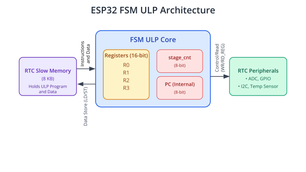
Registers
The FSM ULP has a minimal set of registers:
- R0, R1, R2, R3: Four 16-bit general-purpose registers. These are used for all arithmetic, logic, and data transfer operations.
- Stage Count Register (
stage_cnt): A special-purpose 8-bit register used primarily in multi-stage ADC measurements. It can also be used as a general-purpose counter in creative ways. - Program Counter (PC): An 8-bit internal register that holds the address of the next instruction. It can only address the first 256 words (1024 bytes) of RTC slow memory. This limits the ULP program size.
| Register | Size | Primary Purpose |
|---|---|---|
| R0, R1, R2, R3 | 16-bit | General-purpose registers for arithmetic, logic, and holding memory addresses or data. |
| stage_cnt | 8-bit | Special-purpose register for multi-stage ADC measurements or as a simple loop counter. Used by the JUMPS instruction. |
| Program Counter (PC) | 8-bit (Internal) | Holds the memory address (offset) of the instruction to be executed. Limited to addresses 0-255. |
Memory
The ULP operates exclusively out of the 8KB of RTC slow memory. This memory is accessible to both the ULP and the main CPUs.
- Instructions and Data: The ULP program itself, as well as any data it needs to persist (like sensor thresholds or counters), must be stored here.
- Word Size: The memory is 32-bit addressable from the main CPU, but the ULP’s instructions are 32 bits wide, composed of a 16-bit instruction and 16 bits of data/parameters. The ULP accesses memory in 32-bit words.
Instruction Set Architecture (ISA)
The FSM ULP has a simple but powerful instruction set. All instructions are 32 bits long. They are designed for specific tasks related to sensor monitoring and system control. The instruction set can be categorized as follows:
| Instruction | Example Syntax | Category | Description |
|---|---|---|---|
| LD | ld r0, r1, 0 | Memory | Loads a word from memory at address (R1 + 0) into R0. |
| ST | st r0, r1, 0 | Memory | Stores the word from R0 into memory at address (R1 + 0). |
| ADD | add r0, r0, r1 | Arithmetic | Adds R0 and R1, stores the result in R0. |
| SUB | sub r0, r0, r1 | Arithmetic | Subtracts R1 from R0, stores the result in R0. |
| JUMP | jump my_label | Flow Control | Unconditionally jumps to the specified label or address. |
| JUMPR | jumpr exit, 0, GE | Flow Control | Conditionally jumps to a relative offset if R0 is Greater or Equal (GE) to 0. |
| RD_REG | rd_reg rtc_reg, 7, 7 | Peripheral | Reads a bitfield (from high bit 7 to low bit 7) from a peripheral register. |
| WAKE | wake | System | Wakes the main CPUs from deep sleep. |
| HALT | halt | System | Stops the ULP until the next timer wakeup event. |
- Memory Instructions:
LD R_dst, R_src, offset: Load a word from memory. The address is calculated as(R_src + offset).ST R_src, R_dst, offset: Store a word to memory. The address is calculated as(R_dst + offset).
- Arithmetic Instructions:
ADD R_dst, R_src1, R_src2: Addition (R_dst = R_src1 + R_src2).SUB R_dst, R_src1, R_src2: Subtraction (R_dst = R_src1 - R_src2).
- Logical Instructions:
AND R_dst, R_src1, R_src2: Bitwise AND.OR R_dst, R_src1, R_src2: Bitwise OR.LSH R_dst, R_src, shift: Left shift.RSH R_dst, R_src, shift: Right shift.
- Branching/Flow Control Instructions:
JUMP target: Unconditional jump to a label or absolute address.JUMPR offset, threshold, condition: Conditional relative jump. Jumps if the value inR0meets thecondition(GT– greater,GE– greater or equal,LT– less than,LE– less than or equal,EQ– equal) relative to thethreshold.JUMPS offset, threshold, condition: Conditional jump based on thestage_cntregister.
- Peripheral Instructions:
WAIT cycles: Pause execution for a number of clock cycles.RD_REG addr, high_bit, low_bit: Read from a peripheral register.WR_REG addr, high_bit, low_bit, data: Write to a peripheral register.ADC_POWER_ON/ADC_POWER_OFF: Control power to the ADC.RD_SAR_ADC unit, channel, R_dst: Perform an ADC reading.
- System Control Instructions:
WAKE: Wake the main CPUs from deep sleep.HALT: Stop ULP execution until the next timer trigger. This is the last instruction in a typical ULP program flow.
The ULP Assembly Toolchain
When you write a ULP assembly file (.S), the ESP-IDF build system uses a special preprocessor and assembler to convert it into a binary format that the ULP can execute.

- Assembly File (
.S): You write your program using the ULP mnemonics. You can define labels for branching and variables in RTC memory. esp32-ulp-elf-as: This assembler converts your assembly code into a ULP-executable ELF file.- Symbol Generation: The build system creates a C header file (
ulp_main.hby default) and a linker script fragment (ulp_main.ld).- The header file contains C-accessible symbols for all global variables and labels defined in your assembly code. This allows your main C application to read/write ULP variables and know the program’s start address.
- The linker script tells the main application’s linker how to place the ULP binary blob in RTC memory.
Practical Example: Wake on ADC Threshold (ESP32 FSM ULP)
This example achieves the same goal as the previous chapter’s RISC-V example, but using FSM assembly for the original ESP32.
Hardware Setup: Connect a potentiometer or a photoresistor to GPIO36 (ADC1_CH0) on an ESP32-WROOM-32 board.
1. Project Setup
- Create a new project targeting the ESP32.
- Create a component for the ULP code, e.g.,
components/ulp_fsm_adc. - Inside this directory, create
ulp_main.SandCMakeLists.txt.
2. ULP Component CMakeLists.txt
This file is simpler than the RISC-V version. It tells the build system where to find the ULP assembly file.
File: components/ulp_fsm_adc/CMakeLists.txt
# CMakeLists.txt for the ULP FSM component

# Specify the ULP assembly source file
set(ULP_APP_NAME ulp_${COMPONENT_NAME})
set(ULP_S_SOURCES "ulp_main.S")
set(ULP_EXP_DEP_SRCS "")

# Register the ULP component
ulp_embed_binary(${ULP_APP_NAME} "${ULP_S_SOURCES}" "${ULP_EXP_DEP_SRCS}")
3. ULP Assembly Program (ulp_main.S)
This is the core of our ULP logic, written in FSM assembly.
File: components/ulp_fsm_adc/ulp_main.S
/*
 * ULP Assembly program to read an ADC channel and wake the main CPU
 * if the reading is below a threshold. For ESP32 FSM ULP.
 */

    // Data section: Define variables in RTC slow memory.
    // The main C code can access these using the generated header.
    .data

    // Last ADC reading. Initialized to 0.
    .global adc_reading
adc_reading:
    .word 0

    // Threshold for waking up the CPU. Initialized to 1000.
    // The main CPU will overwrite this value.
    .global wakeup_threshold
wakeup_threshold:
    .word 1000


    // Code section: The actual program logic starts here.
    .text
    .global entry
entry:
    // --- Step 1: Power on the ADC ---
    // This needs to be done before any reading.
    // Note: ADC power control is a bit complex. For simplicity, we assume
    // the main CPU has configured the ADC power correctly before sleep.
    // adc_power_on // This macro handles the necessary register writes

    // --- Step 2: Perform ADC reading ---
    // Read from ADC1, Channel 0 (GPIO36), and store the result in R0.
    // The 3rd argument is a delay parameter for the SAR ADC.
    rd_sar_adc ADC_UNIT_1, ADC_CHANNEL_0, R0

    // --- Step 3: Store the reading in RTC memory ---
    // Load the address of the 'adc_reading' variable into R1.
    move r1, adc_reading
    // Store the value from R0 into the memory location pointed to by R1.
    st r0, r1, 0

    // --- Step 4: Compare reading with the threshold ---
    // Load the threshold value from memory into R2.
    move r1, wakeup_threshold
    ld r2, r1, 0

    // Subtract the threshold (R2) from the reading (R0).
    // Result is stored back in R0.
    // If adc_reading < threshold, then R0 will be negative.
    sub r0, r0, r2

    // --- Step 5: Conditional jump ---
    // If the result of the subtraction is NOT negative (i.e., reading >= threshold),
    // jump to the 'exit_program' label.
    // The offset '1' means jump 1 instruction forward if condition is met.
    jumpr exit_program, 0, GE

    // --- Step 6: Wake up the main CPU ---
    // This code is only reached if adc_reading < threshold.
    wake
    // Fall through to the exit sequence.

    // --- Step 7: Halt the ULP ---
exit_program:
    // Stop the ULP until the next timer trigger.
    halt
graph TD
    A[Start: ULP Wakes Up];
    B["<b>rd_sar_adc</b><br>Read ADC channel value into R0"];
    C["<b>st r0, r1, 0</b><br>Store R0 to <i>adc_reading</i> variable"];
    D["<b>ld r2, r1, 0</b><br>Load <i>wakeup_threshold</i> into R2"];
    E["<b>sub r0, r0, r2</b><br>Calculate: R0 = Reading - Threshold"];
    F{"<b>jumpr exit_program, 0, GE</b><br>Is R0 >= 0?<br>(i.e. Reading >= Threshold?)"};
    G["<b>wake</b><br>Condition Met: Wake Main CPU"];
    H["<b>halt</b><br>Stop ULP Execution"];

    %% Styling
    classDef start-node fill:#EDE9FE,stroke:#5B21B6,stroke-width:2px,color:#5B21B6;
    classDef process-node fill:#DBEAFE,stroke:#2563EB,stroke-width:1px,color:#1E40AF;
    classDef decision-node fill:#FEF3C7,stroke:#D97706,stroke-width:1px,color:#92400E;
    classDef endo-node-halt fill:#FEE2E2,stroke:#DC2626,stroke-width:2px,color:#991B1B;
    classDef endo-node-wake fill:#D1FAE5,stroke:#059669,stroke-width:2px,color:#065F46;

    class A start-node;
    class B,C,D,E process-node;
    class F decision-node;
    class G endo-node-wake;
    class H endo-node-halt;

    %% Connections
    A --> B --> C --> D --> E --> F;
    F -- "No<br>(Reading < Threshold)" --> G;
    F -- "Yes<br>(Reading >= Threshold)" --> H;
    G --> H;
4. Main Application Code
This C code, running on the main CPU, is very similar to before. It loads the ULP program, sets the wakeup timer, and enters deep sleep.
File: main/main.c
#include <stdio.h>
#include "freertos/FreeRTOS.h"
#include "freertos/task.h"
#include "esp_sleep.h"
#include "esp_log.h"
#include "driver/gpio.h"
#include "driver/rtc_io.h"
#include "soc/rtc_cntl_reg.h"
#include "soc/sens_reg.h"
#include "soc/rtc_io_reg.h"

// Include the generated header file for the ULP program.
#include "ulp_main.h"

static const char *TAG = "MAIN_CPU";

// Extern declarations for the ULP program entry point and variables
extern const uint8_t ulp_main_bin_start[] asm("_binary_ulp_main_bin_start");
extern const uint8_t ulp_main_bin_end[]   asm("_binary_ulp_main_bin_end");

// These are defined in ulp_main.S
extern uint32_t ulp_adc_reading;
extern uint32_t ulp_wakeup_threshold;

void init_ulp_program() {
    esp_err_t err = ulp_load_binary(0, ulp_main_bin_start,
                                    (ulp_main_bin_end - ulp_main_bin_start) / sizeof(uint32_t));
    ESP_ERROR_CHECK(err);

    // Configure ADC1_CH0 (GPIO36) as an RTC IO
    adc1_config_channel_atten(ADC1_CHANNEL_0, ADC_ATTEN_DB_11);
    rtc_gpio_init(GPIO_NUM_36);
    rtc_gpio_set_direction(GPIO_NUM_36, RTC_GPIO_MODE_DISABLED);
    // The ULP will manage this pin during deep sleep
    rtc_gpio_isolate(GPIO_NUM_36);

    // Set the ULP wakeup timer period (e.g., 2 seconds)
    ulp_set_wakeup_period(0, 2000 * 1000);

    // Set the wakeup threshold in the ULP's memory space
    ulp_wakeup_threshold = 500;
    ESP_LOGI(TAG, "ULP wakeup threshold set to %"PRIu32, ulp_wakeup_threshold);
}

void app_main(void)
{
    esp_sleep_wakeup_cause_t cause = esp_sleep_get_wakeup_cause();
    if (cause != ESP_SLEEP_WAKEUP_ULP) {
        ESP_LOGI(TAG, "Not a ULP wakeup, starting ULP program");
        init_ulp_program();
    } else {
        ESP_LOGW(TAG, "Woken up by ULP!");
        // ULP variables are 16-bit, but accessed as 32-bit words from main CPU.
        // We only care about the lower 16 bits.
        ESP_LOGI(TAG, "Last ADC reading from ULP: %"PRIu32, ulp_adc_reading & 0xFFFF);
    }

    ESP_LOGI(TAG, "Entering deep sleep...");
    // Start the ULP program and enter deep sleep
    esp_err_t err = ulp_run((&ulp_entry - RTC_SLOW_MEM) / sizeof(uint32_t));
    ESP_ERROR_CHECK(err);
    esp_deep_sleep_start();
}
5. Build, Flash, and Observe
The steps are identical to the RISC-V example, but ensure your target is set to ESP32.
- Configure:
idf.py menuconfig. No specific ULP option is needed for FSM as it’s always available. - Build:
idf.py build. - Flash:
idf.py -p [PORT] flash. - Monitor: You will see the same behavior: the device sleeps, and when the sensor value on GPIO36 drops below 500, the ULP wakes the main CPU.
Variant Notes
- Assembly Specificity: The assembly language shown here is ONLY for the FSM ULP on the original ESP32. It is completely incompatible with the RISC-V ULP.
- RISC-V ULP (S2, S3, C6, H2): These chips use standard RISC-V assembly. While you can write assembly for them, it’s far more common and practical to use C, as shown in the previous chapter. The instruction set (
add,sub,lw,sw,jal, etc.) is entirely different. You would not use instructions likerd_sar_adcorwake. Instead, you would use memory-mapped registers and function calls provided by the ULP HAL.
Common Mistakes & Troubleshooting Tips
| Mistake / Issue | Symptom(s) | Troubleshooting / Solution |
|---|---|---|
| Mixing Registers and Immediate Values | Assembler fails with an “invalid operand” error during build. | ALU instructions like ADD and SUB can only use registers as sources. You cannot use a raw number (immediate). Wrong: add r0, r0, 100 Correct: move r1, 100 then add r0, r0, r1 |
| Incorrect Memory Addressing Offset | Data is read from or written to the wrong location in RTC memory, leading to corrupt values and bugs that are hard to trace. | The offset for LD and ST instructions is in 32-bit words (4 bytes), not bytes. Example: st r0, r1, 1 stores R0 at the memory address of (R1 + 4 bytes). |
| Forgetting the halt Instruction | The ULP behaves erratically after its first run. Power consumption is higher than expected. The ULP seems to crash or loop. | If a program path doesn’t end in halt or wake, the ULP will continue executing whatever data follows your program in memory, causing chaos. Ensure every possible code path has a defined end. |
| JUMPR Calculation Errors | Program gets stuck in an infinite loop or skips over important instructions. | The relative offset for JUMPR is calculated from the address of the next instruction (PC+1). An offset of 1 jumps over one instruction. Carefully map out your code’s memory addresses to calculate offsets correctly. Refer to the JUMPR Logic diagram. |
| Accessing Assembly Variables from C | The C compiler fails with an “undeclared identifier” error for a variable you defined in your .S file. | The build system prefixes all global symbols from assembly with ulp_ for use in C code. Assembly: adc_reading: .word 0 C Code: extern uint32_t ulp_adc_reading; |
Exercises
- ULP Blink in Assembly: Write a ULP assembly program that toggles an RTC GPIO every time it runs. You will need to use
RD_REGandWR_REGto manipulate theRTC_GPIO_OUT_REG. - Event Counter: Implement the ULP event counter from the previous chapter’s exercises, but in FSM assembly. Create a
run_countvariable in the data section and increment it on every run. - Debounced Wakeup: Modify the ADC example to only wake the CPU if the reading is below the threshold for 3 consecutive runs. (Hint: Use a counter variable in RTC memory).
- Two-Threshold Wakeup: Write a ULP program that wakes the CPU if an ADC reading goes outside a given range (i.e.,
reading < low_thresholdORreading > high_threshold). - Stage Counter Fun: Use the
stage_cntregister and theJUMPSinstruction to create a simple state machine. For example, on the first run, measure ADC channel 0; on the second, measure channel 3; on the third, compare the results.
Summary
- The ESP32’s FSM ULP is a simple co-processor with four 16-bit registers (R0-R3) and a specialized instruction set.
- ULP assembly programming provides the highest level of control and power efficiency for the original ESP32.
- The toolchain (
esp32-ulp-elf-as) assembles.Sfiles and generates C headers (ulp_main.h) to link the ULP program with the main application. - Instructions are divided into categories: memory (
LD/ST), arithmetic (ADD/SUB), branching (JUMP/JUMPR), peripheral access (RD_REG/WR_REG), and system control (WAKE/HALT). - All ULP code and shared data must reside in the 8KB of RTC slow memory.
- This FSM assembly is specific to the original ESP32 and is not used on newer ESP32 variants with the RISC-V ULP.
Further Reading
- ESP32 ULP Coprocessor Documentation (FSM): https://docs.espressif.com/projects/esp-idf/en/v5.1.3/esp32/api-reference/system/ulp.html
- ULP Instruction Set Reference: https://docs.espressif.com/projects/esp-idf/en/latest/esp32/api-reference/system/ulp_instruction_set.html
- ESP32 Technical Reference Manual (Chapter: ULP Coprocessor): https://www.espressif.com/sites/default/files/documentation/esp32_technical_reference_manual_en.pdf
