
Chapter 218: Building Management System (BMS) Integration
Chapter Objectives
By the end of this chapter, you will be able to:
- Understand the role and architecture of a Building Management System (BMS).
- Identify common BMS communication protocols like Modbus, BACnet, and KNX.
- Differentiate between gateway and native device integration architectures.
- Implement an ESP32 as a smart sensor node that exposes data over Modbus TCP.
- Understand the concept of mapping physical sensor data to protocol-specific data models (e.g., Modbus registers).
- Use standard tools to test and validate communication with your ESP32-based BMS device.
- Recognize and troubleshoot common challenges in BMS integration projects.
Introduction
Throughout this volume, we have explored a multitude of protocols for controlling specific aspects of a building, from DMX for lighting to EnOcean for wireless sensors. But how do all these disparate systems come together? How does a modern building coordinate its heating, ventilation, and air conditioning (HVAC) with its lighting, access control, and energy consumption monitoring to operate efficiently and intelligently? The answer lies in the Building Management System, or BMS.
A BMS is the central nervous system of a smart building, a high-level platform that supervises, controls, and optimizes all installed electromechanical services. For our custom ESP32 devices to participate in this ecosystem, they must learn to speak the language of the BMS.
This chapter serves as a capstone for our exploration of building automation. We will learn how to bridge the gap between our low-cost, powerful ESP32 solutions and the high-level world of commercial BMS. We will transform our ESP32 from a standalone device into a legitimate field node, ready to be integrated into a large-scale, centrally managed building environment.
Theory
What is a Building Management System (BMS)?
A BMS, sometimes called a Building Automation System (BAS), is a computer-based control system that supervises and manages a building’s mechanical and electrical equipment. Think of it as the building’s brain. Its primary goals are to ensure occupant comfort, maintain a safe environment, and optimize energy efficiency.
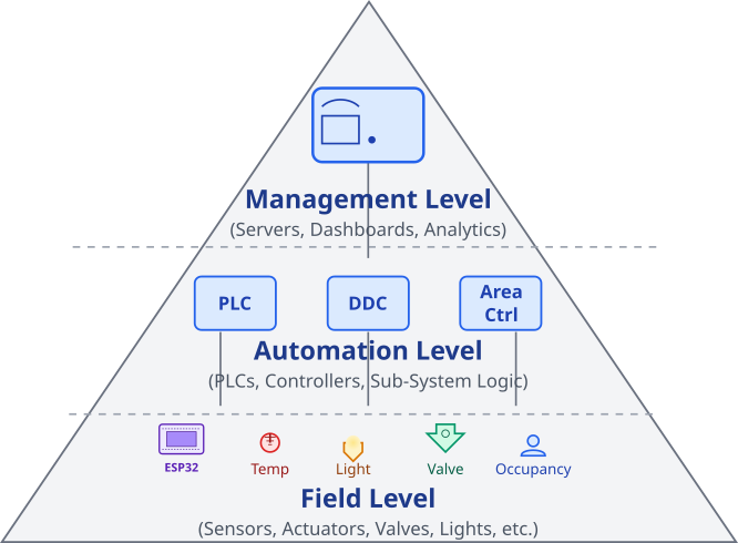
A typical BMS architecture is hierarchical, often visualized as a pyramid:
- Management Level: At the top is the central server and operator workstation. This is where building managers can view dashboards, analyze historical data, respond to alarms, and define high-level strategies (e.g., “reduce energy consumption during off-peak hours”).
- Automation/Control Level: In the middle are powerful area controllers or programmable logic controllers (PLCs). Each controller manages a specific subsystem (like the HVAC for the entire 5th floor) or a large piece of equipment (like a central chiller plant). They execute control logic and communicate with both the management level above and the field level below.
- Field Level: At the base of the pyramid are the vast number of sensors and actuators distributed throughout the building. These are the “senses” and “muscles” of the system: temperature sensors, occupancy detectors, control valves, lighting fixtures, and more. Our ESP32 devices typically live at this level.
BMS Integration Architectures
For our ESP32 device to communicate with the upper levels, it must adopt one of two primary architectures:
- Gateway Approach: The ESP32 acts as a translator. It might manage a network of simpler, low-power devices using a protocol like EnOcean, BLE Mesh, or ESP-NOW. It then gathers all this information and “exposes” it to the BMS using a standard BMS protocol like Modbus TCP or BACnet/IP. The ESP32 is a gateway between two different communication worlds.
- Native Device Approach: The ESP32 itself behaves as a standard field device. It directly implements a BMS protocol stack. From the perspective of an automation controller, the ESP32 looks just like any other off-the-shelf sensor or actuator. This is a more direct approach and will be the focus of our practical example.
graph TD

    subgraph "Gateway Approach"
        BMS_G[BMS Automation Controller]
        ESP32_GW[("<b>ESP32 Gateway</b><br>Translates Protocols")]
        Net_A(("Low-Power Network<br><i>(e.g., BLE Mesh, EnOcean)</i>"))
        Sensor1["Simple Sensor"]
        Sensor2["Simple Sensor"]

        BMS_G -- "Modbus TCP or BACnet/IP" --> ESP32_GW
        ESP32_GW -- "Manages" --> Net_A
        Net_A --- Sensor1
        Net_A --- Sensor2
    end

    subgraph "Native Device Approach"
        BMS_N[BMS Automation Controller]
        ESP32_N[("<b>ESP32 Native Device</b><br>Implements BMS Protocol Directly")]
        Sensor3["Onboard or<br>Direct-Attached Sensor"]

        BMS_N -- "Modbus TCP or BACnet/IP" --> ESP32_N
        ESP32_N -- "Reads" --> Sensor3
    end

    style BMS_G fill:#D1FAE5,stroke:#059669,stroke-width:2px,color:#065F46
    style BMS_N fill:#D1FAE5,stroke:#059669,stroke-width:2px,color:#065F46
    style ESP32_GW fill:#DBEAFE,stroke:#2563EB,stroke-width:1px,color:#1E40AF
    style ESP32_N fill:#DBEAFE,stroke:#2563EB,stroke-width:1px,color:#1E40AF
    style Net_A fill:#FEF3C7,stroke:#D97706,stroke-width:1px,color:#92400E
    style Sensor1 fill:#EDE9FE,stroke:#5B21B6,stroke-width:1px,color:#5B21B6
    style Sensor2 fill:#EDE9FE,stroke:#5B21B6,stroke-width:1px,color:#5B21B6
    style Sensor3 fill:#EDE9FE,stroke:#5B21B6,stroke-width:1px,color:#5B21B6
Key BMS Protocols: A Primer
While there are many protocols, a few dominate the industry. An integration engineer must be familiar with them.
- Modbus: As we saw in Chapters 176-180, Modbus is a simple, robust, and widely supported protocol. Its simplicity makes it an excellent choice for custom devices.
- Modbus RTU: Serial-based (RS-485).
- Modbus TCP: TCP/IP-based, uses Wi-Fi or Ethernet. Perfect for our ESP32.
- Data Model: Uses simple 16-bit “registers” (Coils, Discrete Inputs, Input Registers, Holding Registers).
- BACnet (Building Automation and Control Networks): As introduced in Chapter 184, BACnet is the protocol specifically designed for building automation. It’s more complex and feature-rich than Modbus.
- BACnet/IP: The most common implementation, using UDP over IP networks.
- Data Model: Uses an object-oriented model (Analog Input, Binary Output, Schedule, etc.), which provides rich, self-describing context for data points.
- KNX: (Chapter 208) A decentralized standard popular in Europe, especially for residential and light commercial applications. Unlike the master-slave architecture of Modbus or the client-server model of BACnet, KNX devices can communicate directly with each other (peer-to-peer).
| Feature | Modbus | BACnet | KNX |
|---|---|---|---|
| Primary Use | Industrial Automation, Simple Scada | Purpose-built for Building Automation | Home & Light Commercial Automation |
| Complexity | Low | High | Medium |
| Data Model | Simple 16-bit Registers (Coils, Inputs, etc.) | Object-Oriented (Analog Input, Binary Output, Schedule) | Group Addresses & Datapoint Types |
| ESP32 IP Support | Modbus TCP (Excellent support via esp-modbus) | BACnet/IP (Libraries exist, more complex to implement) | KNXnet/IP (Possible, less common than dedicated KNX ICs) |
| Typical Architecture | Master-Slave | Client-Server, Peer-to-Peer | Decentralized / Peer-to-Peer |
| Best for ESP32 Custom Projects | Ideal starting point. Simple, robust, and great library support. | Feasible for complex projects needing rich data context. | Good for integrating into existing KNX systems, especially in Europe. |
The Crucial Task of Data Mapping
No matter the protocol, the core task of integration is data mapping. This is the process of translating a physical value from a sensor into the specific data format of the protocol.
Consider the ESP32’s internal temperature sensor, which gives us a floating-point value like 45.82 °C. Modbus registers are 16-bit integers. How do we represent this? A common technique is scaling:
- Define a scaling factor, for example, 100.
- Multiply the float by the factor:
45.82 * 100 = 4582.0. - Convert to an integer:
4582. - Place this integer value into a 16-bit Modbus Input Register.
The BMS is then configured to know that to get the actual temperature from this device, it must read that specific register and divide the value by 100. This kind of agreement is fundamental to making systems interoperable.
graph TD
    A[Start: ESP32 reads internal sensor] --> B{"temperature_sensor_get_celsius()"};
    B --> C["Raw Value<br><b>float temp_c = 45.82</b>"];
    C --> D[Data Mapping Step:<br><b>Apply Scaling Factor</b>];
    D --> E["temp_c * 100.0f<br><b>Result: 4582.0</b>"];
    E --> F[Data Mapping Step:<br><b>Convert to Protocol Type</b>];
    F --> G["Cast to 16-bit Integer<br><b>uint16_t temp_scaled = 4582</b>"];
    G --> H[Store in Modbus Memory Area];
    H --> I[("Modbus Input Register<br><b>Address: 0, Value: 4582</b>")];
    I --> J[End: Data is ready for BMS Master to read];

    subgraph "BMS / Modbus Master Side"
        K[Master reads Register 0] --> L{Value = 4582};
        L --> M[Apply Inverse Scaling:<br><b>Value / 100.0</b>];
        M --> N[("Interpreted Temperature<br><b>45.82 °C</b>")];
    end

    style A fill:#EDE9FE,stroke:#5B21B6,stroke-width:2px,color:#5B21B6
    style J fill:#D1FAE5,stroke:#059669,stroke-width:2px,color:#065F46
    style B fill:#FEF3C7,stroke:#D97706,stroke-width:1px,color:#92400E
    style D fill:#DBEAFE,stroke:#2563EB,stroke-width:1px,color:#1E40AF
    style F fill:#DBEAFE,stroke:#2563EB,stroke-width:1px,color:#1E40AF
    style H fill:#DBEAFE,stroke:#2563EB,stroke-width:1px,color:#1E40AF
    style K fill:#EDE9FE,stroke:#5B21B6,stroke-width:2px,color:#5B21B6
    style N fill:#D1FAE5,stroke:#059669,stroke-width:2px,color:#065F46
    style C fill:#FEE2E2,stroke:#DC2626,stroke-width:1px,color:#991B1B
    style E fill:#FEE2E2,stroke:#DC2626,stroke-width:1px,color:#991B1B
    style G fill:#FEE2E2,stroke:#DC2626,stroke-width:1px,color:#991B1B
    style I fill:#FEE2E2,stroke:#DC2626,stroke-width:1px,color:#991B1B
    style L fill:#FEF3C7,stroke:#D97706,stroke-width:1px,color:#92400E
    style M fill:#DBEAFE,stroke:#2563EB,stroke-width:1px,color:#1E40AF
Practical Example: ESP32 as a Modbus TCP Sensor Node
Let’s build a native Modbus TCP device. Our ESP32 will read its internal temperature sensor and make the value available to any Modbus TCP client (a BMS controller, PLC, or PC-based test software).
Hardware Requirements
- An ESP32 development board. That’s it! We will use the built-in temperature sensor (available on most ESP32 variants) and Wi-Fi.
Project Setup and esp-modbus Component
This project relies on the esp-modbus component, which is an official add-on component from Espressif.
- Create a new ESP-IDF project in VS Code.
- Create a folder named
componentsin the root of your project directory (alongsidemain). - Download or clone the
esp-modbusrepository into thiscomponentsfolder. You can get it from here: https://github.com/espressif/esp-modbus- Your project structure should look like this:
my_bms_project/ ├── main/ │ ├── main.c │ └── CMakeLists.txt ├── components/ │ └── esp-modbus/ │ ├── ... (contents of the repo) └── CMakeLists.txt
- Your project structure should look like this:
- Open the
main/CMakeLists.txtand addesp_modbusto theREQUIRESlist:# In idf_component_register(...) REQUIRES esp_netif esp_event nvs_flash esp_wifi esp_log esp_modbus
EnOcean Gateway Code
The code below initializes Wi-Fi, sets up a Modbus TCP server (slave), and creates a task to periodically update a Modbus register with the latest temperature reading.
/*
 * Chapter 218: BMS Integration - Modbus TCP Device
 *
 * This example implements an ESP32 as a Modbus TCP slave device.
 * It reads the internal temperature sensor and exposes the value
 * via a Modbus Input Register.
 *
 * Hardware:
 * - ESP32 board
 *
 * Test with a Modbus TCP Master tool connected to the ESP32's IP address.
 * Read Input Register 0 (address 0x00).
 */
#include <stdio.h>
#include <string.h>
#include "freertos/FreeRTOS.h"
#include "freertos/task.h"
#include "esp_log.h"
#include "esp_wifi.h"
#include "nvs_flash.h"
#include "esp_netif.h"

// Modbus includes
#include "esp_modbus_master.h"
#include "esp_modbus_slave.h"

// Temperature sensor includes
#include "driver/temperature_sensor.h"

static const char *TAG = "BMS_NODE";

// --- Wi-Fi Configuration ---
#define WIFI_SSID      "YOUR_WIFI_SSID"
#define WIFI_PASS      "YOUR_WIFI_PASSWORD"

// --- Modbus Configuration ---
#define MODBUS_PORT                 502 // Standard Modbus TCP port
#define MODBUS_DEV_ID               1
#define MODBUS_INPUT_REG_START      0
#define MODBUS_TEMP_REG_ADDR        0 // Temperature will be at Input Register 0

// Modbus register storage area
static uint16_t input_reg_area[1];

// Simple Wi-Fi connection handler
static void wifi_event_handler(void* arg, esp_event_base_t event_base,
                               int32_t event_id, void* event_data) {
    if (event_id == WIFI_EVENT_STA_START) {
        esp_wifi_connect();
    } else if (event_id == WIFI_EVENT_STA_DISCONNECTED) {
        esp_wifi_connect();
        ESP_LOGI(TAG, "retrying to connect to the AP");
    } else if (event_id == IP_EVENT_STA_GOT_IP) {
        ip_event_got_ip_t* event = (ip_event_got_ip_t*) event_data;
        ESP_LOGI(TAG, "got ip: " IPSTR, IP2STR(&event->ip_info.ip));
    }
}

void setup_wifi(void) {
    ESP_ERROR_CHECK(nvs_flash_init());
    ESP_ERROR_CHECK(esp_netif_init());
    ESP_ERROR_CHECK(esp_event_loop_create_default());
    esp_netif_create_default_wifi_sta();
    wifi_init_config_t cfg = WIFI_INIT_CONFIG_DEFAULT();
    ESP_ERROR_CHECK(esp_wifi_init(&cfg));
    ESP_ERROR_CHECK(esp_event_handler_register(WIFI_EVENT, ESP_EVENT_ANY_ID, &wifi_event_handler, NULL));
    ESP_ERROR_CHECK(esp_event_handler_register(IP_EVENT, IP_EVENT_STA_GOT_IP, &wifi_event_handler, NULL));

    wifi_config_t wifi_config = {
        .sta = {
            .ssid = WIFI_SSID,
            .password = WIFI_PASS,
        },
    };
    ESP_ERROR_CHECK(esp_wifi_set_mode(WIFI_MODE_STA));
    ESP_ERROR_CHECK(esp_wifi_set_config(ESP_IF_WIFI_STA, &wifi_config));
    ESP_ERROR_CHECK(esp_wifi_start());
}

void sensor_update_task(void *pvParameters) {
    ESP_LOGI(TAG, "Installing temperature sensor");
    temperature_sensor_handle_t temp_handle = NULL;
    temperature_sensor_config_t temp_sensor_config = TEMPERATURE_SENSOR_CONFIG_DEFAULT(13, 14); // Check datasheet for your variant
    ESP_ERROR_CHECK(temperature_sensor_install(&temp_sensor_config, &temp_handle));
    ESP_ERROR_CHECK(temperature_sensor_enable(temp_handle));
    ESP_LOGI(TAG, "Temperature sensor enabled.");

    float temp_c;

    while(1) {
        if (temperature_sensor_get_celsius(temp_handle, &temp_c) == ESP_OK) {
            ESP_LOGI(TAG, "Temperature: %.2f C", temp_c);
            // --- DATA MAPPING ---
            // Scale the float by 100 and cast to a 16-bit integer
            uint16_t temp_scaled = (uint16_t)(temp_c * 100.0f);

            // This is thread-safe because we are writing to a simple variable
            // For complex structures, use a mutex (see Chapter 13)
            input_reg_area[MODBUS_TEMP_REG_ADDR] = temp_scaled;
        } else {
            ESP_LOGE(TAG, "Failed to read temperature");
        }
        vTaskDelay(pdMS_TO_TICKS(5000)); // Update every 5 seconds
    }
}


void app_main(void) {
    setup_wifi();
    vTaskDelay(pdMS_TO_TICKS(2000)); // Give wifi time to connect

    // --- Modbus Slave Initialization ---
    void* mbc_slave_handler = NULL;
    ESP_ERROR_CHECK(mbc_slave_init(MB_PORT_TCP, &mbc_slave_handler));

    // Define the communication configuration
    mb_communication_info_t comm_info = {
        .ip_port = MODBUS_PORT,
        .ip_addr_type = MB_IPV4,
        .mb_mode = MB_MODE_TCP,
    };
    ESP_ERROR_CHECK(mbc_slave_setup(&comm_info));

    // Define the data area for the slave to access
    mb_register_area_descriptor_t reg_area = {
        .type = MB_PARAM_INPUT,
        .start_offset = MODBUS_INPUT_REG_START,
        .address = (void*)&input_reg_area,
        .size = sizeof(input_reg_area)
    };
    ESP_ERROR_CHECK(mbc_slave_set_descriptor(reg_area));

    // Start the Modbus slave stack
    ESP_ERROR_CHECK(mbc_slave_start());
    ESP_LOGI(TAG, "Modbus TCP slave started.");

    // Start the task that reads the sensor and updates the register area
    xTaskCreate(sensor_update_task, "sensor_update_task", 4096, NULL, 5, NULL);
}
sequenceDiagram
    participant Main as app_main()
    participant WiFi as Wi-Fi Task
    participant Sensor as sensor_update_task
    participant Modbus as Modbus TCP Slave

    Main->>WiFi: setup_wifi()
    activate WiFi
    WiFi-->>Main: Returns after starting connection
    deactivate WiFi

    Main->>Modbus: mbc_slave_init()
    Main->>Modbus: mbc_slave_setup()
    Main->>Modbus: mbc_slave_set_descriptor(input_reg_area)
    Main->>Modbus: mbc_slave_start()
    activate Modbus
    Note right of Modbus: Starts listening on TCP Port 502

    Main->>Sensor: xTaskCreate(sensor_update_task)
    activate Sensor

    loop Every 5 seconds
        Sensor->>Sensor: Read internal temperature
        Sensor->>Main: Updates input_reg_area[0]
    end

    BMS_Client-->>Modbus: TCP Connect Request
    Modbus-->>BMS_Client: Accept Connection

    loop Client Polling
        BMS_Client->>Modbus: Read Input Register (Addr: 0)
        Modbus->>Main: Reads value from input_reg_area[0]
        Modbus->>BMS_Client: Response with temp value
    end
Build, Flash, and Run
- Configure Wi-Fi: Replace
"YOUR_WIFI_SSID"and"YOUR_WIFI_PASSWORD"in the code with your network credentials. - Build: Click the Build button in VS Code.
- Flash: Connect your ESP32 and click the Flash button.
- Monitor: Open the serial monitor. Note the IP address the ESP32 receives.
Testing with a Modbus Master
To verify our device is working, we need a Modbus TCP Master. You can use a free tool like Modbus Poll for Windows or a Python script.
Using Modbus Poll:
- Download and run the tool.
- Go to
Connection->Connect. - Select
Modbus TCP/IP. - Enter the IP address of your ESP32. The port should be
502. - In the main window, set up the read definition:
- Slave ID:
1 - Function:
04 Read Input Registers - Address:
0 - Quantity:
1
- Slave ID:
- You should see the poll succeed, and the value in the register will be the temperature multiplied by 100. If you warm the ESP32 with your hand, you will see the value increase in real-time.
Variant Notes
- Wi-Fi Capable Variants (ESP32, S2, S3, C3, C6): All these chips are perfectly suited for this example, as they have built-in Wi-Fi. The
esp-modbusTCP slave functionality works well on all of them. - Wired Connectivity: In many commercial BMS installations, wired Ethernet is preferred for reliability. The original ESP32 can be connected to an external Ethernet PHY chip (like a LAN8720). The
esp-modbuscomponent supports Ethernet, requiring only a change in the netif configuration from Wi-Fi to Ethernet. - Internal Temperature Sensor: The example uses the built-in temperature sensor. The
temperature_sensor_config_tmight need slight adjustments depending on the variant. On ESP32-S2/S3, the sensor is more accurate. On C3/S3, it shares hardware with the Wi-Fi ADC, so Wi-Fi must be started before using the sensor. Our code already does this. The ESP32-H2 does not have this peripheral.
Common Mistakes & Troubleshooting Tips
| Mistake / Issue | Symptom(s) | Troubleshooting / Solution |
|---|---|---|
| Build Fails: Component Not Found | Error during build: esp_modbus.h: No such file or directory. |
1. Ensure esp-modbus repo is inside a components/ folder at the project root. 2. Check main/CMakeLists.txt. The REQUIRES or PRIV_REQUIRES list must include esp_modbus. |
| Network Connectivity | ESP32 monitor shows “got ip: …”, but the Modbus Master tool times out or reports “Connection refused”. |
1. Ping Test: Ping the ESP32’s IP from the PC running the Master tool to confirm they are on the same network. 2. Firewall: Check PC firewall rules. Ensure outbound/inbound traffic is allowed for TCP Port 502. |
| Incorrect Modbus Address / Function | Master tool reports a “Slave Device Failure” or “Illegal Data Address” exception (Error Code 02). Data read is always zero. |
1. Function Code: Our code uses an Input Register. Ensure your master is using Function 04 (Read Input Registers), not 03 (Read Holding Registers). 2. Address Index: Code defines the register address as 0. Some GUIs are 1-indexed. Try reading both address 0 and 1 in your tool. |
| Data Format / Scaling Error | A value is successfully read, but it seems nonsensical (e.g., very large, or doesn’t change with temperature). |
1. Confirm Scaling: The read value should be the temperature in °C multiplied by 100. A reading of 2550 should mean 25.50°C. 2. Endianness: Not an issue for single 16-bit registers, but critical for 32-bit values. Ensure Master and Slave agree on byte order (typically handled by the library). |
| Task Watchdog Triggered | ESP32 continuously reboots, with logs showing Task WDT timeout. | This can happen if a task blocks for too long. Ensure the main loop of any custom task you add (like in the exercises) has a delay, e.g., vTaskDelay(), to yield control to the scheduler. |
Exercises
- Implement an Actuator: Add a Holding Register to your Modbus device at address
0. In a separate task, poll the value of this register. If a Modbus master writes1to it, turn on the ESP32’s onboard LED. If it writes0, turn it off. This creates a full sensor/actuator node. - Data Scaling and Range: The internal temperature sensor can report values that, when multiplied by 100, might exceed the
uint16_tmax value (65535) if it’s very hot or negative. Modify the code to handle this by using a signed integer (int16_t) and clamping the value to the register’s limits. - Create a Multi-Sensor Node: Add a simple external sensor (like a photoresistor on an ADC pin to measure light level). Map this new sensor’s value to a second Input Register at address
1. Your device will now report both temperature and light level. - Modbus RTU Gateway: (Advanced) Create a Modbus gateway. Use one ESP32 as a Modbus RTU slave (over UART with an RS-485 transceiver) with a sensor. Use a second ESP32 as the gateway, which acts as a Modbus RTU master to poll the first ESP32, and exposes the data as a Modbus TCP slave to the network. This perfectly mimics a common industrial integration pattern.
Summary
- A BMS is the central control system for a building’s services, organized in a hierarchical structure from management to field levels.
- Integrating custom devices like the ESP32 into a BMS is key to creating flexible and cost-effective smart building solutions.
- Devices can be integrated as gateways (translating protocols) or as native devices (speaking a BMS protocol directly).
- Modbus TCP is a common, IP-based protocol that is well-suited for implementation on the ESP32.
- Data mapping, the process of converting real-world values into the protocol’s data structures, is a critical step in any integration project.
- The
esp-modbuscomponent provides a robust and easy-to-use Modbus stack for ESP-IDF projects. - Thorough testing with standard master tools is essential to validate and troubleshoot a BMS device.
Further Reading
esp-modbusComponent Repository: https://github.com/espressif/esp-modbus- Modbus Organization: Official specifications and information. https://modbus.org/
- BACnet International: The global association for BACnet. https://www.bacnetinternational.org/
- ESP-IDF Temperature Sensor Driver: https://docs.espressif.com/projects/esp-idf/en/v5.1.1/esp32/api-reference/peripherals/temp_sensor.html
