
Chapter 130: I2C Multiple Device Management
Chapter Objectives
After completing this chapter, you will be able to:
- Understand how multiple I2C slave devices share a single I2C bus.
- Implement strategies for addressing and communicating with individual slave devices on a shared bus.
- Write ESP-IDF code to interact with two or more different I2C slave devices.
- Recognize potential I2C address conflicts and basic approaches to handle them.
- Understand the implications of different device speeds and characteristics on a shared I2C bus.
- Design more modular I2C device interaction code.
Introduction
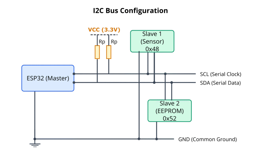
In Chapter 129, we explored the fundamentals of the I2C protocol and learned how to configure the ESP32 as an I2C master to communicate with a single slave device. However, a significant advantage of the I2C protocol is its ability to support multiple slave devices on the same two-wire bus (SDA and SCL). This capability is crucial in modern embedded systems, where a microcontroller often needs to interface with a variety of sensors, memory chips, display controllers, or I/O expanders simultaneously.
For instance, a weather station project might involve reading temperature and humidity from one I2C sensor, barometric pressure from another, and displaying information on an I2C OLED screen. All these devices can coexist and communicate with the ESP32 master over the same I2C bus, provided they are managed correctly.
This chapter will delve into the principles and practices of managing multiple I2C devices. We will cover how addressing works in a multi-slave environment, how the ESP-IDF I2C driver facilitates communication with different slaves, and practical coding examples for such scenarios.
Theory
Addressing Multiple Devices
The core mechanism that allows multiple devices to share an I2C bus without interference is unique slave addressing. As discussed previously, each I2C slave device on the bus must have a unique 7-bit (or, less commonly, 10-bit) address.
- When the master initiates a transaction with a START condition, it immediately broadcasts the 7-bit address of the specific slave it wishes to communicate with, followed by the Read/Write bit.
- All slave devices on the bus listen for this address.
- Only the slave device whose address matches the broadcast address will respond with an Acknowledge (ACK) signal. All other slave devices will ignore the rest of the transaction until a new START or STOP condition occurs.
This addressing scheme ensures that data is exchanged only with the intended slave device, even though multiple devices are physically connected to the same SDA and SCL lines.
Bus Sharing and Operation
- Shared Lines: The SDA and SCL lines, along with their pull-up resistors, are common to all devices (master and slaves) on the bus.
- One Transaction at a Time: The I2C protocol is inherently half-duplex and serial. Only one master can control the bus at any given time, and only one master-slave transaction can occur at a time. The master dictates which slave is active by addressing it.
- No Special Re-initialization for Different Slaves: From the ESP-IDF master’s perspective, once an I2C port (e.g.,
I2C_NUM_0) is initialized and the driver is installed, it can communicate with any slave device on that bus simply by specifying the correct slave address in the transaction commands (e.g., ini2c_master_write_byte()when sending the address byte). There’s no need to reconfigure or reinstall the driver for each different slave device on the same physical bus.
Device Compatibility on a Shared Bus
When multiple devices share an I2C bus, certain compatibility aspects must be considered:
- Bus Speed: The I2C bus will generally operate at a speed compatible with the slowest device on the bus. If you have one device that only supports 100kHz (Standard Mode) and another that supports 400kHz (Fast Mode), you must configure the master to operate at 100kHz to ensure reliable communication with both. Attempting to run the bus faster than a slave can handle will lead to errors.
- Voltage Levels: All devices on the bus should operate at compatible voltage levels (e.g., 3.3V for ESP32). Mixing voltage levels typically requires level shifters.
- Bus Capacitance: Each device added to the I2C bus contributes to the total bus capacitance (due to pin capacitance, trace capacitance, etc.). Higher capacitance can degrade signal rise times, potentially limiting the maximum reliable bus speed or requiring stronger (lower value) pull-up resistors. For a small number of devices on a short intra-board bus, this is often not a major issue, but it’s a factor in larger or more complex systems.
| Factor | Description | Implication for Multi-Device Setup |
|---|---|---|
| Bus Speed | The clock frequency (e.g., 100kHz, 400kHz) at which data is transferred on the SCL line. | The master must operate at a speed supported by all slave devices on the bus. Typically, this is the speed of the slowest device. Running faster can lead to communication errors with slower slaves. |
| Voltage Levels | The logic HIGH and LOW voltage levels used by devices on the bus (e.g., 3.3V for ESP32). | All devices must be compatible with the bus voltage. Mixing voltage levels (e.g., a 5V slave with a 3.3V master) requires level shifter ICs to prevent damage and ensure correct logic interpretation. |
| Bus Capacitance | The total electrical capacitance on the SDA and SCL lines, contributed by the master, slaves, PCB traces, and wiring. | Each added device increases bus capacitance. Higher capacitance slows down signal rise times (due to pull-up resistors). This can limit the maximum reliable bus speed or necessitate stronger (lower value) pull-up resistors. |
| Pull-Up Resistors | Resistors connecting SDA to VCC and SCL to VCC, allowing the open-drain lines to return to a HIGH state. | Their values are critical. Too high (weak pull-up) can cause slow rise times with increased bus capacitance. Too low (strong pull-up) can exceed the current sinking capability of devices. Typical values are 2.2kΩ to 10kΩ (4.7kΩ is common for 3.3V/100-400kHz). May need adjustment based on number of devices and bus length. |
Address Conflicts
The most common issue when working with multiple I2C devices is an address conflict. This occurs if two or more slave devices on the same bus are configured with (or hardwired to) the same I2C address.
- Consequences: If multiple slaves respond to the same address, data corruption is almost certain, and bus operation can become unpredictable. The master might receive an ACK from multiple devices simultaneously, or data read back could be a garbled mix from different sources.
- Solutions:
- Address Select Pins: Many I2C slave ICs provide one or more address select pins (e.g., ADDR, A0, A1). By tying these pins to VCC or GND, you can change the lower bits of the device’s I2C address, allowing multiple identical chips to be used on the same bus. Always consult the device datasheet.
- Different Devices: Choose devices that inherently have different default I2C addresses.
- I2C Multiplexer/Switch: If address conflicts are unavoidable and devices cannot have their addresses changed, an I2C multiplexer (e.g., TCA9548A) can be used. This IC acts like a switch, allowing the master to select one of several downstream I2C buses, effectively isolating devices with conflicting addresses onto separate segments. This is an external hardware solution.
- Separate I2C Buses: If your ESP32 variant has multiple I2C controllers (e.g., ESP32, ESP32-S2, ESP32-S3, ESP32-H2 have two), you can connect devices with conflicting addresses to different physical I2C buses, each managed by a separate controller instance (e.g.,
I2C_NUM_0andI2C_NUM_1).
| Strategy | Description | Pros | Cons |
|---|---|---|---|
| Address Select Pins | Many slave ICs have pins (e.g., A0, A1, ADDR) that can be tied HIGH or LOW to change the lower bits of the I2C address. | Simple hardware solution if supported by the IC. No extra components usually needed. | Limited number of unique addresses (depends on how many select pins). Not all ICs have this feature. |
| Use Different Devices | Select slave devices that have inherently different default I2C addresses. | No hardware or software complexity for addressing itself. | May not always be possible to find suitable alternative devices for the required functionality. |
| I2C Multiplexer/Switch | An IC (e.g., TCA9548A) that acts as a gate, allowing the master to select one of several downstream I2C bus segments. Devices with conflicting addresses can be placed on different segments. | Allows many devices with same addresses. Can isolate bus segments. | Requires an additional IC. Master needs to send commands to the multiplexer to switch channels, adding software overhead. |
| Separate I2C Buses (Ports) | If the MCU (like some ESP32 variants) has multiple I2C controllers, connect conflicting devices to different physical I2C buses, each managed by a separate controller instance (e.g., I2C_NUM_0, I2C_NUM_1). | True parallel operation possible if MCU supports it. Good isolation. | Only available if MCU has multiple I2C controllers. Uses more GPIO pins. |
Practical Examples
The following examples illustrate how to manage and communicate with multiple I2C slave devices using the ESP32. We will assume hypothetical devices for these examples.
Prerequisites:
- Same as Chapter 129: ESP-IDF v5.x, ESP32 board, VS Code.
- For actual testing, you would need at least two distinct I2C slave devices with known, unique addresses, connected to the same I2C bus (SDA, SCL, GND) with appropriate pull-up resistors.
Example 1: Communicating with Two Different Hypothetical Devices
This example demonstrates initializing the I2C master once and then communicating sequentially with two different slave devices, each having a unique address.
Let’s assume:
- Device A: A hypothetical temperature sensor at I2C address
0x48.- To read temperature: Write register address
0x00, then read 2 bytes.
- To read temperature: Write register address
- Device B: A hypothetical EEPROM at I2C address
0x50.- To write data: Write EEPROM memory address (2 bytes, e.g.,
0x0100), then write data byte(s). - To read data: Write EEPROM memory address (2 bytes), then read data byte(s).
- To write data: Write EEPROM memory address (2 bytes, e.g.,
graph TD
    subgraph "Multi-Device I2C Communication Flow (Example 1)"
    A[Start: app_main] --> B("1- Initialize I2C Master Bus<br><span class='code-like'>i2c_master_bus_init()</span>");
    B --> C{"Interact with<br>Temp Sensor (0x48)"};
    C -- Yes --> D["2a- Write Register Address (0x00) to Temp Sensor"];
    D --> E["2b- Perform Repeated START"];
    E --> F["2c- Read 2 Bytes (Temperature Data) from Temp Sensor"];
    F --> G{Process Temp Data};
    G --> H{"Interact with<br>EEPROM (0x50)"};

    H -- Yes --> I["3a- Write EEPROM Memory Address (e.g., 0x0100) to EEPROM"];
    I --> J["3b- Write Data Byte (e.g., 0xA5) to EEPROM"];
    J --> K["3c- (Optional Delay for EEPROM Write Cycle)"];
    K --> L["3d- Write EEPROM Memory Address (e.g., 0x0100) to EEPROM for Read"];
    L --> M["3e- Perform Repeated START"];
    M --> N["3f- Read Data Byte from EEPROM"];
    N --> O{Verify EEPROM Data};
    O --> P[End of Example Interactions];

    C -- No --> H;
    H -- No --> P;

    classDef default fill:#f9f9f9,stroke:#333,stroke-width:1px,color:#333,font-family:'Open Sans';
    classDef primary fill:#EDE9FE,stroke:#5B21B6,stroke-width:2px,color:#5B21B6;
    classDef process fill:#DBEAFE,stroke:#2563EB,stroke-width:1px,color:#1E40AF;
    classDef success fill:#D1FAE5,stroke:#059669,stroke-width:2px,color:#065F46;
    classDef decision fill:#FEF3C7,stroke:#D97706,stroke-width:1px,color:#92400E;
    classDef io fill:#FEE2E2,stroke:#DC2626,stroke-width:1px,color:#991B1B;

    class A,P primary;
    class B,D,E,F,I,J,K,L,M,N process;
    class C,H,G,O decision;


    end
#include <stdio.h>
#include "freertos/FreeRTOS.h"
#include "freertos/task.h"
#include "driver/i2c.h"
#include "esp_log.h"
#include "esp_idf_version.h"

static const char *TAG = "multi_device_i2c";

#define I2C_MASTER_SCL_IO           22      /*!< GPIO number used for I2C master clock */
#define I2C_MASTER_SDA_IO           21      /*!< GPIO number used for I2C master data  */
#define I2C_MASTER_NUM              I2C_NUM_0 /*!< I2C port number for master dev */
#define I2C_MASTER_FREQ_HZ          100000  /*!< I2C master clock frequency */
#define I2C_MASTER_TX_BUF_DISABLE   0       /*!< I2C master doesn't need buffer */
#define I2C_MASTER_RX_BUF_DISABLE   0       /*!< I2C master doesn't need buffer */

#define WRITE_BIT                   I2C_MASTER_WRITE /*!< I2C master write */
#define READ_BIT                    I2C_MASTER_READ  /*!< I2C master read */
#define ACK_CHECK_EN                0x1     /*!< I2C master will check ack from slave*/
#define ACK_VAL                     0x0     /*!< I2C ack value */
#define NACK_VAL                    0x1     /*!< I2C nack value */

// Device Specifics
#define TEMP_SENSOR_ADDR            0x48    /*!< Hypothetical Temperature Sensor Address */
#define TEMP_SENSOR_REG_TEMP        0x00    /*!< Hypothetical Temperature Register */

#define EEPROM_ADDR                 0x50    /*!< Hypothetical EEPROM Address */
#define EEPROM_MEM_ADDR_HIGH        0x01    /*!< Hypothetical EEPROM Memory Address High Byte */
#define EEPROM_MEM_ADDR_LOW         0x00    /*!< Hypothetical EEPROM Memory Address Low Byte */

/**
 * @brief Initialize I2C master
 */
static esp_err_t i2c_master_bus_init(void)
{
    i2c_config_t conf = {
        .mode = I2C_MODE_MASTER,
        .sda_io_num = I2C_MASTER_SDA_IO,
        .scl_io_num = I2C_MASTER_SCL_IO,
        .sda_pullup_en = GPIO_PULLUP_ENABLE,
        .scl_pullup_en = GPIO_PULLUP_ENABLE,
        .master.clk_speed = I2C_MASTER_FREQ_HZ,
    };
    esp_err_t err = i2c_param_config(I2C_MASTER_NUM, &conf);
    if (err != ESP_OK) {
        ESP_LOGE(TAG, "I2C param config failed: %s", esp_err_to_name(err));
        return err;
    }
    err = i2c_driver_install(I2C_MASTER_NUM, conf.mode, I2C_MASTER_RX_BUF_DISABLE, I2C_MASTER_TX_BUF_DISABLE, 0);
    if (err != ESP_OK) {
        ESP_LOGE(TAG, "I2C driver install failed: %s", esp_err_to_name(err));
        return err;
    }
    ESP_LOGI(TAG, "I2C master bus initialized successfully on port %d", I2C_MASTER_NUM);
    return ESP_OK;
}

/**
 * @brief Read temperature from hypothetical sensor
 */
static esp_err_t read_temperature_sensor(uint8_t *temp_data, size_t len)
{
    if (len < 2) return ESP_ERR_INVALID_ARG; // Expecting to read 2 bytes for temp

    i2c_cmd_handle_t cmd = i2c_cmd_link_create();
    // Write: Send START, Slave Address + Write Bit, Register Address
    i2c_master_start(cmd);
    i2c_master_write_byte(cmd, (TEMP_SENSOR_ADDR << 1) | WRITE_BIT, ACK_CHECK_EN);
    uint8_t reg_addr = TEMP_SENSOR_REG_TEMP;
    i2c_master_write_byte(cmd, reg_addr, ACK_CHECK_EN);

    // Read: Send Repeated START, Slave Address + Read Bit, Read Data, Send STOP
    i2c_master_start(cmd); // Repeated start
    i2c_master_write_byte(cmd, (TEMP_SENSOR_ADDR << 1) | READ_BIT, ACK_CHECK_EN);
    if (len > 1) {
        i2c_master_read(cmd, temp_data, len - 1, ACK_VAL);
    }
    i2c_master_read_byte(cmd, temp_data + len - 1, NACK_VAL);
    i2c_master_stop(cmd);

    esp_err_t ret = i2c_master_cmd_begin(I2C_MASTER_NUM, cmd, pdMS_TO_TICKS(1000));
    i2c_cmd_link_delete(cmd);

    if (ret == ESP_OK) {
        ESP_LOGI(TAG, "Temperature sensor (0x%02X) read successful. Raw: 0x%02X 0x%02X", TEMP_SENSOR_ADDR, temp_data[0], temp_data[1]);
    } else {
        ESP_LOGE(TAG, "Failed to read from temperature sensor (0x%02X): %s", TEMP_SENSOR_ADDR, esp_err_to_name(ret));
    }
    return ret;
}

/**
 * @brief Write a byte to hypothetical EEPROM
 */
static esp_err_t write_to_eeprom(uint8_t mem_addr_high, uint8_t mem_addr_low, uint8_t data_byte)
{
    i2c_cmd_handle_t cmd = i2c_cmd_link_create();
    i2c_master_start(cmd);
    i2c_master_write_byte(cmd, (EEPROM_ADDR << 1) | WRITE_BIT, ACK_CHECK_EN);
    i2c_master_write_byte(cmd, mem_addr_high, ACK_CHECK_EN); // EEPROM Memory Address High
    i2c_master_write_byte(cmd, mem_addr_low, ACK_CHECK_EN);  // EEPROM Memory Address Low
    i2c_master_write_byte(cmd, data_byte, ACK_CHECK_EN);     // Data to write
    i2c_master_stop(cmd);

    esp_err_t ret = i2c_master_cmd_begin(I2C_MASTER_NUM, cmd, pdMS_TO_TICKS(1000));
    i2c_cmd_link_delete(cmd);

    if (ret == ESP_OK) {
        ESP_LOGI(TAG, "EEPROM (0x%02X) write to 0x%02X%02X successful. Data: 0x%02X", EEPROM_ADDR, mem_addr_high, mem_addr_low, data_byte);
    } else {
        ESP_LOGE(TAG, "Failed to write to EEPROM (0x%02X): %s", EEPROM_ADDR, esp_err_to_name(ret));
    }
    return ret;
}

/**
 * @brief Read a byte from hypothetical EEPROM
 */
static esp_err_t read_from_eeprom(uint8_t mem_addr_high, uint8_t mem_addr_low, uint8_t *data_byte)
{
    i2c_cmd_handle_t cmd = i2c_cmd_link_create();
    // Write phase: set memory address pointer
    i2c_master_start(cmd);
    i2c_master_write_byte(cmd, (EEPROM_ADDR << 1) | WRITE_BIT, ACK_CHECK_EN);
    i2c_master_write_byte(cmd, mem_addr_high, ACK_CHECK_EN);
    i2c_master_write_byte(cmd, mem_addr_low, ACK_CHECK_EN);

    // Read phase
    i2c_master_start(cmd); // Repeated start
    i2c_master_write_byte(cmd, (EEPROM_ADDR << 1) | READ_BIT, ACK_CHECK_EN);
    i2c_master_read_byte(cmd, data_byte, NACK_VAL);
    i2c_master_stop(cmd);

    esp_err_t ret = i2c_master_cmd_begin(I2C_MASTER_NUM, cmd, pdMS_TO_TICKS(1000));
    i2c_cmd_link_delete(cmd);

    if (ret == ESP_OK) {
        ESP_LOGI(TAG, "EEPROM (0x%02X) read from 0x%02X%02X successful. Data: 0x%02X", EEPROM_ADDR, mem_addr_high, mem_addr_low, *data_byte);
    } else {
        ESP_LOGE(TAG, "Failed to read from EEPROM (0x%02X): %s", EEPROM_ADDR, esp_err_to_name(ret));
    }
    return ret;
}


void app_main(void)
{
    ESP_ERROR_CHECK(i2c_master_bus_init());

    // Interact with Temperature Sensor
    uint8_t temp_buffer[2];
    if (read_temperature_sensor(temp_buffer, sizeof(temp_buffer)) == ESP_OK) {
        // Process temperature data, e.g. (temp_buffer[0] << 8 | temp_buffer[1]) * 0.0625;
        float temperature = ((temp_buffer[0] << 8) | temp_buffer[1]) / 16.0; // Example conversion
        ESP_LOGI(TAG, "Processed Temperature: %.2f C", temperature);
    }

    vTaskDelay(pdMS_TO_TICKS(100)); // Small delay between device interactions

    // Interact with EEPROM
    uint8_t eeprom_data_to_write = 0xA5;
    uint8_t eeprom_data_read;

    if (write_to_eeprom(EEPROM_MEM_ADDR_HIGH, EEPROM_MEM_ADDR_LOW, eeprom_data_to_write) == ESP_OK) {
        vTaskDelay(pdMS_TO_TICKS(10)); // EEPROMs often need a short write cycle time
        if (read_from_eeprom(EEPROM_MEM_ADDR_HIGH, EEPROM_MEM_ADDR_LOW, &eeprom_data_read) == ESP_OK) {
            if (eeprom_data_read == eeprom_data_to_write) {
                ESP_LOGI(TAG, "EEPROM write-read verification successful!");
            } else {
                ESP_LOGW(TAG, "EEPROM write-read verification FAILED. Read 0x%02X, Wrote 0x%02X", eeprom_data_read, eeprom_data_to_write);
            }
        }
    }

    // --- Using simplified helper functions (ESP-IDF v5.1+) for one of the devices ---
    #if ESP_IDF_VERSION >= ESP_IDF_VERSION_VAL(5, 1, 0)
    ESP_LOGI(TAG, "--- Using i2c_master_transmit_receive for Temp Sensor (ESP-IDF v5.1+) ---");
    uint8_t temp_reg = TEMP_SENSOR_REG_TEMP;
    uint8_t temp_data_simple[2];

    esp_err_t ret_simple = i2c_master_transmit_receive(I2C_MASTER_NUM,
                                                       TEMP_SENSOR_ADDR,
                                                       &temp_reg, 1, // Write 1 byte (register address)
                                                       temp_data_simple, 2, // Read 2 bytes
                                                       pdMS_TO_TICKS(1000));
    if (ret_simple == ESP_OK) {
        ESP_LOGI(TAG, "Temp Sensor (0x%02X) read via transmit_receive successful. Raw: 0x%02X 0x%02X",
                 TEMP_SENSOR_ADDR, temp_data_simple[0], temp_data_simple[1]);
        float temperature_simple = ((temp_data_simple[0] << 8) | temp_data_simple[1]) / 16.0;
        ESP_LOGI(TAG, "Processed Temperature (simple): %.2f C", temperature_simple);
    } else {
        ESP_LOGE(TAG, "i2c_master_transmit_receive for Temp Sensor failed: %s", esp_err_to_name(ret_simple));
    }
    #endif

    // Optional: Delete driver if no longer needed
    // ESP_ERROR_CHECK(i2c_driver_delete(I2C_MASTER_NUM));
    // ESP_LOGI(TAG, "I2C master bus driver deleted.");
}
Code Explanation:
i2c_master_bus_init(): This function is called once to configure and install the I2C driver forI2C_MASTER_NUM. It’s identical to the initialization in Chapter 129.- Device-Specific Functions:
read_temperature_sensor(): Implements the logic to read from the hypothetical temperature sensor. It first writes the target register address (TEMP_SENSOR_REG_TEMP), then performs a repeated START, and then reads two bytes of temperature data.write_to_eeprom(): Writes a data byte to a specified 2-byte memory address in the EEPROM.read_from_eeprom(): Reads a data byte from a specified 2-byte memory address in the EEPROM. This also involves first writing the memory address, then a repeated START, then reading.
- Addressing: Notice how each function uses the specific
_ADDRdefine for the target device (e.g.,TEMP_SENSOR_ADDR,EEPROM_ADDR) when constructing the address byte:(DEVICE_ADDR << 1) | OPERATION_BIT. app_main():- Initializes the I2C bus once.
- Calls
read_temperature_sensor()to interact with the first device. - Adds a small delay (optional, but can be good practice).
- Calls
write_to_eeprom()andread_from_eeprom()to interact with the second device. - Includes an example using
i2c_master_transmit_receive(ESP-IDF v5.1+) for the temperature sensor, which simplifies common write-then-read operations.
- No Re-initialization: The I2C bus driver (
I2C_MASTER_NUM) is not re-initialized between talking to the temperature sensor and the EEPROM. The same initialized port handles transactions to different slave addresses.
Build Instructions:
- Save as
main.cin your ESP-IDF project’smaindirectory. - Update
CMakeLists.txtin themaindirectory:idf_component_register(SRCS "main.c" INCLUDE_DIRS "."). - Build:
idf.py build.
Run/Flash/Observe Steps:
- Connect your ESP32. If you have actual I2C devices matching the addresses and register patterns, connect them. Otherwise, the code will run, but I2C transactions will likely fail with NACKs or timeouts.
- Flash and Monitor:
idf.py -p (PORT) flash monitor. - Observe logs. If devices are present and correctly addressed, you’ll see success messages. Otherwise, error messages will indicate issues.
Example 2: Simple I2C Device Abstraction (Conceptual Structure)
When dealing with multiple, potentially complex I2C devices, abstracting device interactions into structures and dedicated functions can make your code much cleaner and more maintainable.
graph LR
    subgraph "Application Layer (app_main.c)"
        AppMain["app_main()"]
    end

    subgraph "Device Abstraction Layer (i2c_devices.c / .h)"
        direction LR
        subgraph "Temp Sensor Abstraction"
            TS_Init["my_temp_sensor_init()"]
            TS_ReadID["my_temp_sensor_read_id()"]
            TS_ReadTemp["my_temp_sensor_read_temperature()"]
        end
        subgraph "EEPROM Abstraction"
            EE_Init["my_eeprom_init()"]
            EE_Write["my_eeprom_write_byte()"]
            EE_Read["my_eeprom_read_byte()"]
        end
    end

    subgraph "ESP-IDF I2C Driver (driver/i2c.h)"
        direction LR
        IDF_CmdLinkCreate["i2c_cmd_link_create()"]
        IDF_MasterWrite["i2c_master_write_byte()/write()"]
        IDF_MasterRead["i2c_master_read_byte()/read()"]
        IDF_CmdBegin["i2c_master_cmd_begin()"]
        IDF_CmdLinkDelete["i2c_cmd_link_delete()"]
        IDF_TransmitReceive["i2c_master_transmit_receive() (IDF v5.1+)"]
    end

    AppMain --> TS_Init
    AppMain --> TS_ReadID
    AppMain --> TS_ReadTemp
    AppMain --> EE_Init
    AppMain --> EE_Write
    AppMain --> EE_Read

    TS_Init --> IDF_CmdLinkCreate;
    TS_ReadID --> IDF_TransmitReceive;
    TS_ReadTemp --> IDF_TransmitReceive;

    EE_Init --> IDF_CmdLinkCreate;
    EE_Write --> IDF_CmdLinkCreate;
    EE_Write --> IDF_MasterWrite;
    EE_Write --> IDF_CmdBegin;
    EE_Write --> IDF_CmdLinkDelete;

    EE_Read --> IDF_CmdLinkCreate;
    EE_Read --> IDF_MasterWrite;
    EE_Read --> IDF_MasterRead;
    EE_Read --> IDF_CmdBegin;
    EE_Read --> IDF_CmdLinkDelete;


    classDef default fill:#f9f9f9,stroke:#333,stroke-width:1px,color:#333,font-family:'Open Sans';
    classDef applayer fill:#EDE9FE,stroke:#5B21B6,stroke-width:2px,color:#5B21B6;
    classDef abstractlayer fill:#DBEAFE,stroke:#2563EB,stroke-width:1px,color:#1E40AF;
    classDef driverlayer fill:#D1FAE5,stroke:#059669,stroke-width:1px,color:#065F46;

    class AppMain applayer;
    class TS_Init,TS_ReadID,TS_ReadTemp,EE_Init,EE_Write,EE_Read abstractlayer;
    class IDF_CmdLinkCreate,IDF_MasterWrite,IDF_MasterRead,IDF_CmdBegin,IDF_CmdLinkDelete,IDF_TransmitReceive driverlayer;
Here’s a conceptual way to structure it:
// --- In a new header file, e.g., "i2c_devices.h" ---
#ifndef I2C_DEVICES_H
#define I2C_DEVICES_H
#include "driver/i2c.h"
#include "esp_err.h"
// Forward declaration if needed, or define i2c_master_num globally/pass it around
// extern i2c_port_t g_i2c_port;
// Generic I2C Device Structure
typedef struct {
i2c_port_t port_num;
uint8_t device_address; // 7-bit address
// You could add more device-specific config here if needed
} i2c_device_handle_t;
// --- Temperature Sensor Specific ---
#define MY_TEMP_SENSOR_ADDR 0x48
#define MY_TEMP_SENSOR_REG_WHO_AM_I 0x0F // Example register
#define MY_TEMP_SENSOR_REG_DATA 0x00
esp_err_t my_temp_sensor_init(i2c_device_handle_t *dev, i2c_port_t port);
esp_err_t my_temp_sensor_read_id(i2c_device_handle_t *dev, uint8_t *id);
esp_err_t my_temp_sensor_read_temperature(i2c_device_handle_t *dev, int16_t *temperature);
// --- EEPROM Specific ---
#define MY_EEPROM_ADDR 0x50
esp_err_t my_eeprom_init(i2c_device_handle_t *dev, i2c_port_t port);
esp_err_t my_eeprom_write_byte(i2c_device_handle_t *dev, uint16_t mem_addr, uint8_t data);
esp_err_t my_eeprom_read_byte(i2c_device_handle_t *dev, uint16_t mem_addr, uint8_t *data);
#endif // I2C_DEVICES_H
// --- In a corresponding C file, e.g., "i2c_devices.c" ---
/*
#include "i2c_devices.h"
#include "esp_log.h"
static const char *TAG_DEV = "i2c_device_lib";
// Define g_i2c_port if using globally, e.g.
// i2c_port_t g_i2c_port = I2C_NUM_0;
esp_err_t my_temp_sensor_init(i2c_device_handle_t *dev, i2c_port_t port) {
if (!dev) return ESP_ERR_INVALID_ARG;
dev->port_num = port;
dev->device_address = MY_TEMP_SENSOR_ADDR;
ESP_LOGI(TAG_DEV, "Temp sensor initialized with addr 0x%02X on port %d", dev->device_address, dev->port_num);
// Optionally, try to read WHO_AM_I register here to verify connection
return ESP_OK;
}
esp_err_t my_temp_sensor_read_id(i2c_device_handle_t *dev, uint8_t *id) {
if (!dev || !id) return ESP_ERR_INVALID_ARG;
// Simplified using i2c_master_transmit_receive (ESP-IDF v5.1+)
// Assumes the WHO_AM_I register is 1 byte
#if ESP_IDF_VERSION >= ESP_IDF_VERSION_VAL(5, 1, 0)
uint8_t reg_to_read = MY_TEMP_SENSOR_REG_WHO_AM_I;
return i2c_master_transmit_receive(dev->port_num, dev->device_address,
®_to_read, 1,
id, 1,
pdMS_TO_TICKS(100));
#else
// Implement with command links for older IDF versions or more complex sequences
ESP_LOGW(TAG_DEV, "my_temp_sensor_read_id: Full implementation needed for IDF < 5.1 or use command links.");
return ESP_ERR_NOT_SUPPORTED;
#endif
}
// Implement other functions (my_temp_sensor_read_temperature, my_eeprom_init, etc.)
// These functions would encapsulate the i2c_cmd_link_create/delete and i2c_master_cmd_begin logic
// or use the simpler helper functions like i2c_master_transmit_receive.
// Each function would use dev->port_num and dev->device_address.
*/
Using the Abstraction in app_main:
/*
// In app_main.c
#include "i2c_devices.h" // Your new header
// ... (I2C bus init as before) ...
i2c_device_handle_t temp_sensor;
i2c_device_handle_t eeprom;
my_temp_sensor_init(&temp_sensor, I2C_MASTER_NUM);
my_eeprom_init(&eeprom, I2C_MASTER_NUM); // Assuming both on same port
uint8_t sensor_id;
if (my_temp_sensor_read_id(&temp_sensor, &sensor_id) == ESP_OK) {
ESP_LOGI(TAG, "Temp Sensor ID: 0x%02X", sensor_id);
}
int16_t current_temp;
if (my_temp_sensor_read_temperature(&temp_sensor, ¤t_temp) == ESP_OK) {
ESP_LOGI(TAG, "Temperature (raw): %d", current_temp);
}
// ... EEPROM operations using my_eeprom_write_byte(&eeprom, ...), etc.
*/
This abstraction separates the low-level I2C communication logic for each device type into its own set of functions, making app_main cleaner and device interactions more reusable.
Variant Notes
- Single Bus, Multiple Devices: The core ESP-IDF I2C driver usage for communicating with multiple devices on a single I2C bus (e.g., all connected to
I2C_NUM_0) is identical across all ESP32 variants (ESP32, S2, S3, C3, C6, H2). The key is to use the correct slave address for each transaction. - Multiple I2C Buses (Ports):
- ESP32, ESP32-S2, ESP32-S3, ESP32-H2: These variants have two I2C controllers (
I2C_NUM_0andI2C_NUM_1). This is beneficial if:- You have devices with conflicting I2C addresses that cannot be changed.
- You need to operate different sets of devices at different I2C speeds (e.g., one bus at 100kHz, another at 400kHz).
- You want to physically isolate groups of devices.In such cases, you would initialize each I2C port separately (e.g., one call to i2c_param_config and i2c_driver_install for I2C_NUM_0 with its GPIOs, and another set of calls for I2C_NUM_1 with different GPIOs). Transactions would then target the specific i2c_port_t number.
- ESP32-C3, ESP32-C6: These variants typically have one primary I2C controller (
I2C_NUM_0) available for general use. If you need to manage devices with conflicting addresses on these variants, an external I2C multiplexer would be the primary solution, or you’d need to ensure devices have configurable addresses.
- ESP32, ESP32-S2, ESP32-S3, ESP32-H2: These variants have two I2C controllers (
- Pin Assignments: Always ensure the GPIOs chosen for SDA and SCL for each I2C port are valid for your specific ESP32 variant and board layout and do not conflict with other peripherals.
Common Mistakes & Troubleshooting Tips
| Mistake / Issue with I2C Multiplexer | Symptom(s) | Troubleshooting / Solution |
|---|---|---|
| Incorrect Multiplexer I2C Address | Cannot communicate with the multiplexer itself. Master gets NACK or timeout when trying to write to the multiplexer’s control register. | Verify the 7-bit I2C address of the multiplexer IC (e.g., TCA9548A often defaults to 0x70, but can be changed with address pins A0-A2). Check datasheet and hardware configuration. Use I2C scanner on the main bus segment to find the multiplexer. |
| Failure to Select a Channel | Master communicates with the multiplexer successfully, but attempts to communicate with downstream slave devices fail (NACK/timeout). | Ensure you are writing the correct byte to the multiplexer’s control register to select the desired downstream channel. For TCA9548A, writing 0x01 selects channel 0, 0x02 for channel 1, 0x04 for channel 2, etc. (bitmask). Writing 0x00 deselects all channels. |
| Communication Issues on Selected Downstream Channel | Multiplexer channel selection seems correct, but communication with a specific slave on that channel fails. | This becomes a standard I2C troubleshooting scenario for that specific downstream segment. Check slave address, pull-ups on that segment (if needed, though mux often handles this), wiring to the slave, and slave power. The issue is likely with the slave or that segment, not the mux itself. |
| Multiplexer Not Powered or Incorrectly Wired | Multiplexer does not appear on I2C scan. No communication possible with mux or any downstream device. | Verify VCC and GND connections to the multiplexer IC. Check enable pin (if any) is correctly set. Ensure SDA/SCL lines from master are correctly wired to the multiplexer’s upstream SDA/SCL pins. |
| Attempting to Communicate with Device on Unselected Channel | Communication fails for a device that is on a channel not currently selected by the multiplexer. | Always select the correct channel on the multiplexer *before* attempting to communicate with any device on that downstream segment. Only one channel (or set of channels, if mux supports multiple active) is connected at a time. |
| Address Conflict on a Single Downstream Channel | Two devices on the *same* downstream channel (e.g., both on Mux Channel 0) have the same I2C address. | The multiplexer isolates channels from each other, but not devices *within* the same channel. Resolve this as a standard I2C address conflict for that specific segment (e.g., change device address select pins if possible). |
| Forgetting Pull-up Resistors (Upstream or Downstream) | Unreliable communication, lines stuck low. | The main I2C bus (master to multiplexer) needs pull-ups. Most multiplexer breakout boards include pull-ups on the downstream channels. If using a bare mux IC, check its datasheet; you might need pull-ups on each active downstream segment as well, though often the mux provides them internally or passes through the upstream pull-ups when a channel is selected. |
| Mux Reset Pin Issues | Multiplexer is unresponsive or in an unknown state. | If the multiplexer has a reset pin, ensure it’s handled correctly (e.g., pulled high for normal operation, or pulsed low if a reset is needed). Refer to the specific multiplexer’s datasheet. |
Exercises
- Three Device Interaction:Extend “Practical Example 1” to include a third hypothetical I2C device (e.g., a light sensor at address 0x29). Define its registers and implement functions to read data from it. Ensure all three devices are interacted with sequentially in app_main.
- Device Structure Implementation:Fully implement the device abstraction concept from “Practical Example 2” for the hypothetical temperature sensor and EEPROM. Create the i2c_devices.h and i2c_devices.c files. Implement all the function stubs shown (e.g., my_temp_sensor_read_temperature, my_eeprom_write_byte, my_eeprom_read_byte). Your app_main should then use these abstracted functions.
- I2C Multiplexer/Switch Research (Conceptual):Research an I2C multiplexer IC like the TCA9548A.
- Briefly explain its purpose and how it works.
- How would you control such a device from the ESP32 (it’s itself an I2C slave)?
- Describe a scenario where using this multiplexer would be beneficial in an ESP32 project. (This is a conceptual exercise; no coding required).
- Bus Scan with Device Identification (Advanced):Building on the I2C bus scanner from Chapter 129 (Exercise 3):
- Assume you have two known types of devices that could be on your bus, e.g., “SensorTypeA” (has a WHO_AM_I register at
0x0Fthat returns0xA1) and “SensorTypeB” (has an ID register at0x00that returns0xB2). - Modify your scanner: when it finds a device at an address, it then attempts to read the known WHO_AM_I / ID register for both SensorTypeA and SensorTypeB.
- Based on the value read (if any), try to print if the found device is “SensorTypeA”, “SensorTypeB”, or “Unknown Device”.
- Note: This is challenging as a general solution because a read attempt to a wrong register on an unknown device might cause issues or return arbitrary data. Be cautious and focus on the logic flow.
- Assume you have two known types of devices that could be on your bus, e.g., “SensorTypeA” (has a WHO_AM_I register at
Summary
- Multiple I2C slave devices can share the same SDA and SCL lines, each uniquely identified by its 7-bit address.
- The ESP32 I2C master communicates with a specific slave by sending its address after a START condition.
- The ESP-IDF I2C driver is initialized once per I2C port; subsequent transactions to different slaves on that port only require specifying the target slave’s address.
- Address conflicts are a primary concern and can be resolved by changing slave addresses, using I2C multiplexers, or utilizing separate I2C ports on multi-port ESP32 variants.
- The bus speed should be compatible with the slowest device on the shared bus segment.
- Abstracting device interactions into dedicated functions or structures improves code organization when dealing with multiple I2C peripherals.
- Careful error checking for each transaction is essential in multi-device setups.
Further Reading
- ESP-IDF I2C Driver Documentation: (Same as Chapter 129)
- I2C Multiplexers/Switches:
- Datasheet for TCA9548A (Texas Instruments) or similar I2C multiplexer ICs.
- Adafruit TCA9548A Guide: Adafruit TCA9548A 1-to-8 I2C Multiplexer Breakout
- Application Notes on I2C Bus Design:
- Search for application notes from semiconductor manufacturers (e.g., NXP, TI) on “I2C bus design considerations” or “managing multiple I2C slaves.”
