
Chapter 50: WiFi Performance Optimization Techniques
Chapter Objectives
By the end of this chapter, you will be able to:
- Understand the key factors that influence WiFi performance, including throughput, latency, and reliability.
- Identify common bottlenecks in ESP32 WiFi applications.
- Implement techniques to measure and benchmark WiFi throughput using tools like iperf.
- Optimize TCP/IP socket communication parameters for better performance.
- Configure ESP32 WiFi transmit power and understand its impact.
- Briefly understand WiFi rate control and its relevance.
- Leverage features like A-MPDU for improved efficiency.
- Effectively use WiFi power-saving modes while considering performance trade-offs.
- Appreciate the impact of antenna design, placement, and RF environment on WiFi performance.
- Apply application-level strategies to enhance data transfer efficiency.
- Utilize ESP-IDF tools and configurations for WiFi performance analysis and tuning.
Introduction
Throughout this volume, we’ve explored how to connect your ESP32 to WiFi networks, manage different modes, and implement various communication protocols. While establishing a connection is the first step, ensuring that the connection performs optimally is crucial for many IoT applications. Whether it’s streaming sensor data, receiving commands with low latency, or maximizing battery life for a connected device, WiFi performance can significantly impact the user experience and overall system effectiveness.
Poor WiFi performance can manifest as slow data transfer, laggy responses, frequent disconnections, or excessive power drain. This chapter focuses on techniques and strategies to optimize WiFi performance on your ESP32 devices. We will cover aspects ranging from low-level RF considerations and ESP-IDF configurations to application-level protocol choices and data handling practices. By understanding these optimization levers, you can fine-tune your ESP32 applications to achieve the desired balance of throughput, latency, reliability, and power efficiency.
Theory
Factors Affecting WiFi Performance
WiFi performance is a multifaceted issue influenced by a combination of environmental, hardware, software, and application-specific factors:
- RF (Radio Frequency) Environment:
- Interference: Other WiFi networks, Bluetooth devices, microwave ovens, and even some industrial equipment operating in the 2.4 GHz band can cause interference, leading to packet loss and retransmissions.
- Distance and Obstacles: Signal strength (RSSI) weakens with distance and when passing through obstacles like walls, furniture, or metal enclosures.
- Channel Congestion: Too many WiFi networks operating on the same or overlapping channels can lead to collisions and reduced throughput.
- Multipath Fading: RF signals reflecting off surfaces can arrive at the receiver at slightly different times, causing constructive or destructive interference.
- WiFi Protocol Overhead:
- The 802.11 standard itself has overhead associated with beacons, probe requests/responses, acknowledgments (ACKs), and MAC layer headers.
- Retransmissions due to errors or collisions add further overhead and reduce effective throughput.
- Access Point (AP) Capabilities and Configuration:
- Router Quality: The capabilities of the WiFi router (AP), including its processor, memory, antenna quality, and firmware, play a significant role.
- AP Settings: Channel width (20MHz vs. 40MHz in 2.4GHz), security protocols (WPA2 vs. WPA3), and Quality of Service (QoS) settings on the AP can impact performance.
- Number of Connected Clients: An AP overloaded with too many clients will result in reduced performance for each client.
- ESP32 Hardware and Software:
- Antenna Design & Placement: The ESP32 module’s antenna (PCB trace or external) and its integration into your product (enclosure, nearby components) are critical.
- ESP32 Processing Power (CPU): Handling network stacks (LwIP), application logic, and encryption/decryption consumes CPU resources. High CPU load can become a bottleneck.
- Memory (RAM): Insufficient RAM for network buffers can limit throughput.
- ESP-IDF WiFi Stack Configuration: Settings within the ESP-IDF, such as buffer sizes, transmit power, and rate control algorithms, affect performance.
- Application Behavior:
- Data Packet Size: Sending many small packets incurs more overhead than sending fewer, larger packets (up to a certain limit, e.g., MTU).
- Frequency of Transmission: Constant high-frequency transmissions can strain the network and the ESP32.
- Protocol Choices: TCP (reliable, connection-oriented) has more overhead than UDP (unreliable, connectionless). Application protocols like HTTP and MQTT also add their own overhead.
Key Performance Metrics
| Metric | Description | Unit | Importance |
|---|---|---|---|
| Throughput | Actual rate of successful data transfer over the communication channel. | bps, kbps, Mbps | Key for bulk data transfer, streaming. Higher is generally better. |
| Latency (Ping Time) | Time delay for a packet to travel from source to destination (and often back). | ms (milliseconds) | Critical for real-time applications, command-response systems. Lower is better. |
| Reliability (Packet Loss Rate) | Percentage of packets that fail to reach their destination. | % | High loss leads to retransmissions (TCP), data gaps (UDP), and reduced effective throughput. Lower is better. |
| Jitter | Variation in packet arrival times (variation in latency). | ms | Important for streaming audio/video to avoid glitches. Lower is better. |
| Power Consumption | Amount of energy consumed by the ESP32 during WiFi operations. | mA, µA, mW | Crucial for battery-operated devices. Lower is better for longevity. |
| RSSI (Received Signal Strength Indicator) | Measure of the power present in a received radio signal. | dBm | Indicates signal quality. Higher (less negative) values are better (e.g., -50 dBm is better than -80 dBm). |
Optimization Strategies Overview
Optimizing WiFi performance involves a holistic approach:
- Physical Layer & RF Optimization: Improving signal quality, reducing interference, choosing appropriate channels, and optimizing antenna design/placement.
- MAC Layer Optimization: Leveraging 802.11 features like packet aggregation (A-MPDU) and configuring transmit power.
- IP & Transport Layer Optimization: Tuning TCP/IP stack parameters (e.g., socket buffers, TCP options like Nagle’s algorithm).
- Application Layer Optimization: Efficient data formatting, payload aggregation, choosing appropriate application protocols, and managing connection frequency.
- ESP-IDF Specific Configurations: Utilizing ESP-IDF settings for WiFi driver, LwIP, and power management.
Practical Examples and Techniques
1. Measuring Throughput with iperf
iperf is a widely used network testing tool for measuring TCP and UDP bandwidth performance. ESP-IDF provides an iperf example that allows the ESP32 to act as an iperf client or server.
%%{
  init: {
    'theme': 'base',
    'fontFamily': 'Open Sans',
    'themeVariables': {
      'fontFamily': 'Open Sans',
      'textColor': '#1F2937',
      'lineColor': '#A78BFA',
      'primaryColor': '#DBEAFE', /* Process */
      'primaryBorderColor': '#2563EB',
      'primaryTextColor': '#1E40AF',
      'actorFill': '#EDE9FE', /* Light purple for actors */
      'actorBorder': '#5B21B6',
      'actorTextColor': '#5B21B6',
      'noteBkgColor': '#FEF3C7',
      'noteTextColor': '#92400E'
    }
  }
}%%
graph LR
    subgraph "Test Environment"
        PC[("PC / Laptop<br>iperf3 Server/Client")]:::actor
        AP[("WiFi Access Point<br>(Router)")]:::process
        ESP32[("ESP32 Device<br>iperf Client/Server")]:::actor
    end

    PC <-- WiFi Connection --> AP
    ESP32 <-- WiFi Connection --> AP

    subgraph "Scenario 1: ESP32 as Client"
        direction TB
        PC_Server[("PC: iperf3 -s")] -- "1- Start Server" --> AP_Connect1[AP]
        ESP32_Client[("ESP32: iperf (client mode)<br>Target IP: PC_IP")] -- "2- Connect to Server via AP" --> AP_Connect1
        AP_Connect1 -- "Data Flow (TCP/UDP)" --> PC_Server
        PC_Server -- "Results" --> Output1[("iperf Output<br>on PC & ESP32")]
    end

    subgraph "Scenario 2: ESP32 as Server"
        direction TB
        ESP32_Server[("ESP32: iperf (server mode)")] -- "1- Start Server" --> AP_Connect2[AP]
        PC_Client[("PC: iperf3 -c ESP32_IP")] -- "2- Connect to Server via AP" --> AP_Connect2
        AP_Connect2 -- "Data Flow (TCP/UDP)" --> ESP32_Server
        ESP32_Server -- "Results" --> Output2[("iperf Output<br>on PC & ESP32")]
    end

    classDef actor fill:#EDE9FE,stroke:#5B21B6,stroke-width:1.5px,color:#5B21B6,fontWeight:bold;
    classDef process fill:#DBEAFE,stroke:#2563EB,stroke-width:1px,color:#1E40AF;
Setup:
- PC (Server/Client): Install
iperf3on your computer. - ESP32 (Client/Server): Use the ESP-IDF
wifi/iperfexample project.- Locate it in
$IDF_PATH/examples/wifi/iperf. - Configure the ESP32 with your WiFi network credentials in the example’s
sdkconfig.defaultsor viamenuconfig. - You can configure the ESP32 as an iperf server or client via
menuconfigin the example’s settings.
- Locate it in
Running the Test (ESP32 as Client, PC as Server):
- On your PC, start the iperf server:
iperf3 -sThis will start an iperf3 server listening on the default port (5201). Note your PC’s IP address. - On the ESP32 (flashed with iperf example configured as client):
- Configure the example via
menuconfigto set the server IP address (your PC’s IP) and other parameters (TCP/UDP, duration, etc.). - Build and flash the example to your ESP32.
- Monitor the ESP32’s serial output. It will attempt to connect to the iperf server on your PC and start the test.
- Both the ESP32’s serial monitor and the PC’s iperf3 server window will display throughput results.
- Configure the example via
Code Snippet (Conceptual – from iperf example logic):
The ESP-IDF iperf example handles the socket creation and iperf protocol. The key is configuring it:
// In menuconfig for the iperf example:
// Example Wi-Fi SSID: "YOUR_SSID"
// Example Wi-Fi Password: "YOUR_PASSWORD"
// Example Iperf Protocol: TCP / UDP
// Example Iperf operation mode: Client
// Example Iperf Server IP: "PC_IP_ADDRESS"
// Example Iperf Bandwidth (for UDP client): (e.g., 10M for 10 Mbps)
Interpreting Results:
iperfwill show bandwidth, transfer size, and for UDP, jitter and packet loss.- This gives you a baseline of your ESP32’s raw network performance in its current environment.
2. Optimizing TCP/IP Socket Communication
When using TCP sockets for reliable communication (e.g., HTTP, MQTT over TCP):
%%{
  init: {
    'theme': 'base',
    'fontFamily': 'Open Sans',
    'themeVariables': {
      'fontFamily': 'Open Sans',
      'textColor': '#1F2937',
      'lineColor': '#A78BFA',
      'primaryColor': '#DBEAFE', /* Process */
      'primaryBorderColor': '#2563EB',
      'primaryTextColor': '#1E40AF',
      'actorFill': '#EDE9FE', /* Light purple for actors */
      'actorBorder': '#5B21B6',
      'actorTextColor': '#5B21B6',
      'noteBkgColor': '#FFFBEB', /* Lighter yellow for notes */
      'noteTextColor': '#78350F'
    }
  }
}%%
sequenceDiagram
    actor App as Application
    participant TCPStack as TCP Stack (ESP32)
    participant Network as Network
    actor Server as Remote Server

    Note over App, TCPStack: Scenario 1: <br>Nagle's Algorithm ENABLED (Default)

    App->>TCPStack: Send("Data1") (Small)
    TCPStack->>TCPStack: Buffer "Data1" (Waiting for more data or ACK)
    App->>TCPStack: Send("Data2") (Small)
    TCPStack->>Network: TCP Segment ("Data1" + "Data2" + Headers)
    Network->>Server: Segment Arrives
    Server-->>Network: ACK
    Network-->>TCPStack: ACK Received

    Note over App, TCPStack: Latency potentially higher for Data1,<br>but fewer packets, <br>better network efficiency for bulk.

    %% Separator for clarity - Mermaid doesn't have explicit visual separators in sequence diagrams
    App->>App: --- Scenario 2 ---

    Note over App, TCPStack: Scenario 2: <br>Nagle's Algorithm DISABLED <br>(TCP_NODELAY = 1)

    App->>TCPStack: Send("DataA") (Small)
    TCPStack->>Network: TCP Segment ("DataA" + Headers) - Sent Immediately
    Network->>Server: Segment "DataA" Arrives
    Server-->>Network: ACK for "DataA"
    Network-->>TCPStack: ACK for "DataA" Received

    App->>TCPStack: Send("DataB") (Small)
    TCPStack->>Network: TCP Segment ("DataB" + Headers) - Sent Immediately
    Network->>Server: Segment "DataB" Arrives
    Server-->>Network: ACK for "DataB"
    Network-->>TCPStack: ACK for "DataB" Received

    Note over App, TCPStack: Latency potentially lower for<br> DataA & DataB individually,<br>but more packets, potentially <br>lower overall network efficiency for bulk.
- Socket Buffer Sizes (
SO_SNDBUF,SO_RCVBUF):- Larger send and receive buffers can improve throughput, especially for high-latency networks, by allowing more data to be “in flight.” However, they consume more RAM.These are typically configured using
setsockopt().
int sockfd = socket(AF_INET, SOCK_STREAM, 0);// ... connect ... int sndbuf_size = 32 * 1024; // 32 KBint rcvbuf_size = 32 * 1024; // 32 KBsetsockopt(sockfd, SOL_SOCKET, SO_SNDBUF, &sndbuf_size, sizeof(sndbuf_size));setsockopt(sockfd, SOL_SOCKET, SO_RCVBUF, &rcvbuf_size, sizeof(rcvbuf_size));
- Larger send and receive buffers can improve throughput, especially for high-latency networks, by allowing more data to be “in flight.” However, they consume more RAM.These are typically configured using
- TCP NoDelay (
TCP_NODELAY):- Nagle’s algorithm, enabled by default in TCP, tries to reduce the number of small packets by buffering small outgoing data segments and sending them together. This can introduce latency for applications sending small, time-sensitive messages.
- Setting
TCP_NODELAYdisables Nagle’s algorithm, sending data immediately. This can reduce latency but may decrease overall throughput due to more, smaller packets.
int optval = 1; setsockopt(sockfd, IPPROTO_TCP, TCP_NODELAY, &optval, sizeof(optval)); - TCP Keep-Alive:
- Helps detect dead connections and prevent intermediate firewalls/NATs from closing idle connections. It doesn’t directly improve throughput but enhances reliability.
int keepalive = 1;     // Enable keepalive
int keepidle = 60;     // Idle time in seconds before sending first keepalive probe
int keepinterval = 5;  // Interval in seconds between keepalive probes
int keepcount = 3;     // Number of probes before timing out

setsockopt(sockfd, SOL_SOCKET, SO_KEEPALIVE, &keepalive, sizeof(keepalive));
setsockopt(sockfd, IPPROTO_TCP, TCP_KEEPIDLE, &keepidle, sizeof(keepidle));
setsockopt(sockfd, IPPROTO_TCP, TCP_KEEPINTVL, &keepinterval, sizeof(keepinterval));
setsockopt(sockfd, IPPROTO_TCP, TCP_KEEPCNT, &keepcount, sizeof(keepcount));
| Socket Option | Level | Description | Impact & Use Case |
|---|---|---|---|
SO_SNDBUF |
SOL_SOCKET |
Sets the size of the send buffer for a socket. | Larger buffers can improve TCP throughput, especially on high-latency links, by allowing more data in flight. Consumes RAM. Limited by LwIP system config. |
SO_RCVBUF |
SOL_SOCKET |
Sets the size of the receive buffer for a socket. | Larger buffers can improve TCP throughput by allowing the sender to send more data before waiting for ACKs. Consumes RAM. Limited by LwIP system config. |
TCP_NODELAY |
IPPROTO_TCP |
Disables Nagle’s algorithm. Sends small packets immediately. | Reduces latency for small, frequent messages (e.g., command/control). May decrease overall throughput for bulk data transfer due to increased packet overhead. |
SO_KEEPALIVE |
SOL_SOCKET |
Enables periodic keep-alive probes on an idle TCP connection. | Detects dead connections and can prevent NATs/firewalls from closing idle connections. Improves long-term connection reliability. |
TCP_KEEPIDLE |
IPPROTO_TCP |
Time (seconds) connection must be idle before sending first keep-alive probe. | Used in conjunction with SO_KEEPALIVE. |
TCP_KEEPINTVL |
IPPROTO_TCP |
Interval (seconds) between keep-alive probes. | Used in conjunction with SO_KEEPALIVE. |
TCP_KEEPCNT |
IPPROTO_TCP |
Number of unanswered probes before considering connection dead. | Used in conjunction with SO_KEEPALIVE. |
3. WiFi Transmit Power Configuration
The ESP32’s WiFi transmit (TX) power can be adjusted.
- API:
esp_wifi_set_max_tx_power(int8_t power)power: Value in 0.25 dBm units. For example, a value of80corresponds to 20 dBm. The valid range is typically documented (e.g., for ESP32, often around 8 to 82, representing +2dBm to +20.5dBm). Check the API guide for your specific chip.
- Trade-offs:
- Higher TX Power: Can increase range and improve signal strength at the receiver, potentially improving throughput in marginal conditions. However, it consumes more power and can increase interference to nearby networks.
- Lower TX Power: Reduces power consumption and interference but decreases range.
- Default: ESP-IDF usually sets a default TX power. It’s often not necessary to set it to the absolute maximum unless range is a critical issue and interference/power are less concerning.
// Example: Set max TX power to ~18.5 dBm (74 * 0.25 dBm)
// Value needs to be within the chip's supported range.
esp_err_t err = esp_wifi_set_max_tx_power(74);
if (err == ESP_OK) {
    ESP_LOGI(TAG, "Successfully set Wi-Fi TX power.");
} else {
    ESP_LOGE(TAG, "Failed to set Wi-Fi TX power: %s", esp_err_to_name(err));
}
Warning: Setting TX power too high can sometimes be counterproductive, leading to increased noise or even violating regulatory limits in your region. Always test thoroughly.
4. WiFi Rate Control (802.11 Protocol Mode)
WiFi devices dynamically adjust their data transmission rate based on channel conditions (signal strength, interference). This is known as rate control or rate adaptation.
- While ESP-IDF doesn’t typically expose fine-grained control over the specific rate adaptation algorithm to the user application, you can influence the set of possible rates by selecting the WiFi protocol mode:
esp_wifi_set_protocol(wifi_if_t ifx, uint8_t protocol_bitmap)protocol_bitmap: Can beWIFI_PROTOCOL_11B,WIFI_PROTOCOL_11G,WIFI_PROTOCOL_11N. You can also OR them (e.g.,WIFI_PROTOCOL_11B | WIFI_PROTOCOL_11G | WIFI_PROTOCOL_11N).
- Using only older protocols (like 11B) will limit maximum throughput but might offer better range in some noisy environments. 11N offers higher rates. Most modern APs support 11b/g/n. The default is usually a combination (e.g., 11bgn).
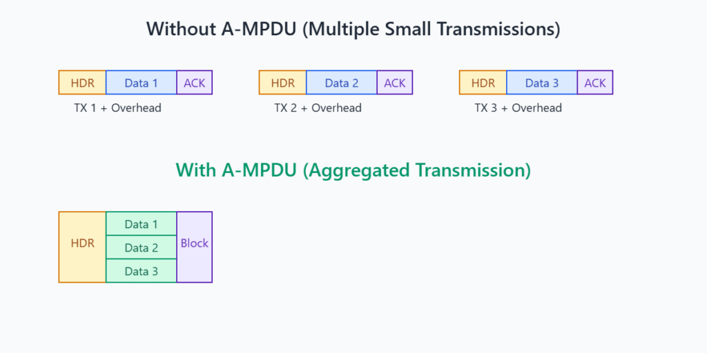
5. A-MPDU (Aggregate MAC Protocol Data Unit)
A-MPDU is a MAC layer aggregation technique that combines multiple MAC Protocol Data Units (MPDUs) into a single larger frame for transmission. This reduces MAC layer overhead and can significantly improve throughput, especially for 802.11n and later standards.
- ESP-IDF Configuration: A-MPDU TX/RX is generally enabled by default in ESP-IDF for 802.11n modes.
- You can check and potentially influence A-MPDU settings via
menuconfig:Component config->Wi-FiEnable A-MPDU Tx(CONFIG_ESP_WIFI_AMPDU_TX_ENABLED)Enable A-MPDU Rx(CONFIG_ESP_WIFI_AMPDU_RX_ENABLED)
- There might be sub-options for buffer sizes or number of aggregated frames.
- Disabling A-MPDU can sometimes help troubleshoot interoperability issues with older APs but will typically reduce performance.
6. WiFi Power Save Modes and Performance
As discussed in Chapter 39, ESP32 supports WiFi power-saving modes (WIFI_PS_MIN_MODEM, WIFI_PS_MAX_MODEM, WIFI_PS_NONE).
WIFI_PS_NONE: WiFi radio is always active. Offers the lowest latency and potentially highest throughput but consumes the most power.WIFI_PS_MIN_MODEM(Modem Sleep / Light Sleep): The CPU is running, but the WiFi radio periodically sleeps and wakes up to listen for AP beacons (DTIM beacons).- Impact: Introduces latency because the ESP32 might miss a transmission if it’s asleep and has to wait for the next DTIM interval or wake-up. Throughput can also be affected if the sleep/wake cycles are frequent relative to data transmission.
- The AP buffers downstream packets for sleeping stations.
WIFI_PS_MAX_MODEM: A deeper version of modem sleep, potentially with longer sleep intervals. (Actual behavior can be implementation-specific and might not differ vastly from MIN_MODEM in all scenarios).
Dynamic Adjustment:
For applications that have periods of high activity and periods of inactivity, you can dynamically switch power-save modes:
// During high data transfer:
esp_wifi_set_ps(WIFI_PS_NONE);

// During idle periods:
esp_wifi_set_ps(WIFI_PS_MIN_MODEM);
| Power Save Mode | Description | Typical Power Consumption | Latency Impact | Throughput Impact | Best Use Case |
|---|---|---|---|---|---|
WIFI_PS_NONE |
WiFi radio is always active. CPU is active. | Highest | Lowest (best responsiveness) | Potentially Highest (radio always ready) | Latency-critical applications, high continuous throughput needs, mains-powered devices. |
WIFI_PS_MIN_MODEM (Modem Sleep / Light Sleep) |
CPU is running, WiFi radio periodically sleeps and wakes for AP beacons (DTIM). | Moderate (significantly lower than NONE) | Increased (waits for DTIM or listen interval). Downstream packets buffered by AP. | Can be reduced if sleep/wake cycles are frequent relative to data transfer. | Battery-powered devices with intermittent data transfer, where moderate latency is acceptable. Most common power-save mode. |
WIFI_PS_MAX_MODEM |
Similar to MIN_MODEM, potentially with longer sleep intervals or deeper radio sleep. (Exact behavior can be chip/IDF version specific). | Low to Moderate (often similar to MIN_MODEM) | Similar to or slightly higher than MIN_MODEM. | Similar to MIN_MODEM. | Applications where MIN_MODEM is used, potentially for slightly more power savings if latency tolerance allows. |
| Dynamic Switching | Application switches between WIFI_PS_NONE and WIFI_PS_MIN_MODEM based on activity. |
Varies (low during idle, high during activity) | Low during active periods, higher during idle. | High during active periods. | Applications with distinct active data transfer phases and idle periods, balancing performance and power. |
Further Optimization Techniques
Antenna Design and Placement
- Good Antenna is Key: A well-designed and properly matched antenna is fundamental. For PCB antennas, follow manufacturer guidelines strictly. For external antennas, use appropriate connectors and cables.
- Placement:
- Keep the antenna area clear of metal objects, ground planes (unless designed to be near one), and noisy components.
- Enclosure materials (plastic, metal) can significantly affect antenna performance. Test within the final enclosure.
- Orientation matters. Experiment with device orientation for best signal.

Channel Selection
- Use a WiFi analyzer tool (on a PC or smartphone) to identify the least congested channels in your deployment environment.
- Configure your AP to use one of these less congested channels.
- If the ESP32 is acting as an AP, you can set its channel in
wifi_config_t.ap.channel.
Minimizing Protocol Overhead (Application Level)
- Payload Aggregation: If sending many small pieces of data (e.g., sensor readings), buffer them and send them as a single larger packet periodically, rather than many small individual packets. This reduces the per-packet overhead of WiFi, IP, and TCP/UDP headers.
- UDP vs. TCP:
- Use UDP for applications where some packet loss is acceptable and low latency is critical (e.g., live sensor data streams for non-critical monitoring, some types of gaming data).
- Use TCP for applications requiring reliable delivery (e.g., firmware updates, critical commands, web content).
- Efficient Data Serialization: Use compact binary formats (like Protocol Buffers, MessagePack, or custom binary structures) instead of verbose text formats like JSON or XML for data exchange, especially for frequently transmitted data. This reduces packet size.
- Reduce “Chattiness”: Minimize the number of round-trips or separate messages required for an operation. For example, an API that requires multiple HTTP requests to achieve one logical action is less efficient than one that achieves it in a single request.
ESP-IDF WiFi Configuration (via menuconfig)
Explore menuconfig under Component config -> Wi-Fi and Component config -> LWIP for various tunable parameters:
- LwIP Buffer Sizes:
TCP_MSS,TCP_SND_BUF,TCP_WND,UDP_RECV_BUF_SIZE, etc. Adjusting these can impact memory usage and throughput. Defaults are generally balanced. - WiFi TX/RX Buffer Numbers/Sizes: Options like
CONFIG_ESP_WIFI_TX_BUFFER,CONFIG_ESP_WIFI_RX_BUFFER_NUM,CONFIG_ESP_WIFI_STATIC_RX_BUFFER_NUM. - Listen Interval (
wifi_config_t.sta.listen_interval): How often a station in power-save mode wakes up to listen for beacons. Higher values save more power but increase latency for receiving downstream unicast packets. - DTIM Period (AP setting, client listens accordingly): The AP’s DTIM period determines how often it sends beacons indicating buffered multicast/broadcast data. Stations in power save wake for these DTIM beacons.
Variant Notes
While the general principles of WiFi optimization apply to all WiFi-enabled ESP32 variants, there are some differences to consider:
- ESP32: Dual-core, good processing power for handling network stack and applications. Mature WiFi stack.
- ESP32-S2: Single-core. While capable, very high throughput applications might see more CPU contention compared to dual-core variants. Excellent low-power performance.
- ESP32-S3: Dual-core, similar to ESP32 but with AI acceleration and other improvements. Supports 802.11 b/g/n. Some S3 modules might have improved antenna designs or PSRAM for larger buffers.
- ESP32-C3: Single-core RISC-V. Designed for simpler, cost-effective IoT applications. WiFi performance is generally good for its class. Supports 802.11 b/g/n.
- ESP32-C6:
- WiFi 6 (802.11ax) Support: This is a major differentiator. WiFi 6 brings features like OFDMA (Orthogonal Frequency-Division Multiple Access) and Target Wake Time (TWT).
- OFDMA: Improves efficiency and reduces latency in dense environments with many devices by dividing channels into smaller resource units.
- TWT: Allows devices to schedule their wake-up times with the AP, leading to significant power savings for battery-operated devices.
- To benefit from WiFi 6 features, the AP must also be WiFi 6 compatible.
- Even when connected to older APs (WiFi 4/5), the C6’s radio might offer some performance or efficiency improvements.
- WiFi 6 (802.11ax) Support: This is a major differentiator. WiFi 6 brings features like OFDMA (Orthogonal Frequency-Division Multiple Access) and Target Wake Time (TWT).
- Antenna Diversity: Some ESP32 modules (across various series) might offer antenna diversity options (e.g., two antenna connectors or pads), which can improve reliability in environments with multipath fading. This is usually handled at a lower level but is a hardware factor.
- PSRAM: Variants with integrated or external PSRAM can support larger network buffers (e.g., TCP window sizes in LwIP), potentially improving throughput for bulk data transfers.
ESP32-H2: Does not support WiFi, so this chapter’s content is not directly applicable.
Common Mistakes & Troubleshooting Tips
| Mistake / Issue | Symptom(s) | Troubleshooting / Solution |
|---|---|---|
| Focusing Only on ESP32 Code | Poor WiFi performance despite extensive ESP32 code optimization. | Solution: Performance is a system issue. Check AP configuration (channel, channel width, firmware), RF environment (interference, congestion using a WiFi analyzer), and physical distance/obstacles. |
| Unrealistic Throughput Expectations | Frustration that application throughput doesn’t match theoretical WiFi data rates (e.g., 54 Mbps for 802.11g). | Solution: Understand that protocol overhead (WiFi, TCP/IP, application), retransmissions, and RF conditions significantly reduce effective throughput. Use iperf for realistic baseline measurements. |
Using TCP_NODELAY Inappropriately |
Enabling TCP_NODELAY globally, leading to reduced throughput for bulk data transfers. |
Solution: Use TCP_NODELAY judiciously only when low latency for small, frequent messages is critical. It disables Nagle’s algorithm, which can otherwise improve efficiency for larger data streams. |
| Ignoring Power Save Implications | Enabling aggressive power-saving modes (e.g., WIFI_PS_MIN_MODEM) without testing, leading to missed incoming data or unacceptable latency. |
Solution: Test application responsiveness and reliability with power-saving modes active. If quick responses are needed, use WIFI_PS_NONE during active periods or configure listen intervals and DTIM settings carefully. |
| Poor Antenna Integration | Low RSSI, frequent disconnections, poor range, especially when device is in its final enclosure. | Solution: Follow antenna design guidelines strictly. Ensure PCB antenna keep-out areas are respected. Avoid placing antennas near metal or noisy components. Test in the final product enclosure. Consider an external antenna if necessary. |
| Neglecting Application-Level Aggregation | Sending many small, frequent sensor readings or data fragments individually, leading to high overhead and low efficiency. | Solution: Buffer small data pieces and send them as a single larger packet periodically. This reduces the per-packet overhead of WiFi and TCP/IP headers. |
| Using Verbose Data Formats Unnecessarily | Using JSON or XML for frequently transmitted, performance-sensitive data where binary formats would be more efficient. | Solution: For high-frequency data, consider compact binary serialization formats (e.g., Protocol Buffers, MessagePack, custom structures) to reduce packet sizes and transmission times. |
Exercises
- Throughput vs. Distance/Obstacles:
- Set up an ESP32 as an iperf client and a PC as an iperf server.
- Measure TCP throughput with the ESP32 at various distances from the AP (e.g., 1m, 5m, 10m line-of-sight).
- Then, place obstacles (e.g., a wooden door, a brick wall segment if safe and possible, a person) between the ESP32 and AP and re-measure throughput at a fixed distance.
- Document and discuss your findings on how distance and obstacles affect performance.
- Application Payload Aggregation Test:
- Write a simple ESP32 application that sends 100 small messages (e.g., 10 bytes each) to a server (e.g., a Python UDP or TCP echo server on your PC) one by one. Measure the total time taken.
- Modify the application to aggregate these 100 messages into a single larger payload (1000 bytes) and send it once. Measure the total time taken.
- Compare the times and discuss the impact of application-level payload aggregation on perceived performance and network efficiency.
- TX Power and RSSI Observation:
- Configure your ESP32 to connect to your AP.
- Write code to set the ESP32’s max TX power using
esp_wifi_set_max_tx_power()to three different levels (e.g., a low, medium, and high valid value for your chip). - For each power level, observe the RSSI reported by your AP for the ESP32 client (most APs show connected client signal strength in their admin interface). If your AP doesn’t show this, you can use another ESP32 in promiscuous mode to sniff beacons/data from your test ESP32 and estimate RSSI, but this is more advanced.
- Discuss the relationship between set TX power and reported RSSI.
- Impact of
TCP_NODELAYon Latency:- Create an ESP32 TCP client that sends a small message (e.g., 16 bytes) to a TCP echo server on your PC every 200ms.
- Measure the round-trip time (RTT) for these messages (ESP32 sends, server echoes, ESP32 receives echo). Average over many samples.
- Perform this test twice: once with
TCP_NODELAYdisabled (default) and once withTCP_NODELAYenabled. - Compare the average RTTs and discuss if
TCP_NODELAYmade a noticeable difference for this type of traffic.
Summary
- WiFi performance optimization is a multi-faceted task involving RF environment, hardware, protocol configurations, and application design.
- Key metrics include throughput, latency, reliability, and power consumption.
- iperf is a valuable tool for benchmarking raw network throughput.
- Tuning TCP socket options (
SO_SNDBUF,SO_RCVBUF,TCP_NODELAY, Keep-Alive) can improve data transfer efficiency and reliability. - Adjusting WiFi TX power (
esp_wifi_set_max_tx_power()) impacts range and power use. - A-MPDU aggregation, usually enabled by default, improves MAC layer efficiency.
- WiFi power-save modes (
WIFI_PS_MIN_MODEM) save energy but can increase latency; choose based on application needs. - Antenna design and placement are critical for good RF performance.
- Application-level strategies like payload aggregation and efficient data formats significantly reduce overhead.
- ESP32 variants (especially ESP32-C6 with WiFi 6) offer different baseline capabilities and features affecting performance.
- Systematic testing and considering the entire system (ESP32, AP, environment) are key to effective optimization.
Further Reading
- ESP-IDF Wi-Fi Driver API Reference: https://docs.espressif.com/projects/esp-idf/en/v5.4/esp32/api-reference/network/esp_wifi.html
- ESP-IDF LwIP TCP/IP Stack API Reference: https://docs.espressif.com/projects/esp-idf/en/v5.4/esp32/api-reference/protocols/lwip.html (For socket options and LwIP configuration).
- ESP-IDF iperf Example:
$IDF_PATH/examples/wifi/iperf/ - iperf3 Documentation: https://iperf.fr/iperf-doc.php
- Espressif Application Notes on Antenna Design: Search on Espressif’s website for hardware design guidelines and antenna layout recommendations.
- “High Performance Browser Networking” by Ilya Grigorik: (While web-focused, contains excellent explanations of TCP, UDP, and network latency relevant to any networked application).
