
Chapter 261: USB MSC (Mass Storage) Implementation
Chapter Objectives
By the end of this chapter, you will be able to:
- Understand the fundamental principles of the USB Mass Storage Class (MSC).
- Identify which ESP32 variants support USB-OTG for custom device implementation.
- Configure the ESP-IDF project to include the TinyUSB stack for MSC.
- Implement the necessary callbacks to handle SCSI commands from a USB host.
- Use a flash partition as the backing storage for the USB drive.
- Build, flash, and test an ESP32-S2/S3 application that emulates a USB flash drive.
Introduction
In the modern world of embedded systems, the ability to easily transfer data to and from a device is paramount. While wireless methods like WiFi and Bluetooth are common, the universal standard for wired data transfer remains the Universal Serial Bus (USB). One of the most recognizable USB device types is the Mass Storage Class (MSC), commonly known as a flash drive or thumb drive.
Implementing an MSC device on an ESP32 allows it to appear as a standard disk drive when connected to a host computer (PC, Mac, Linux). This powerful feature enables a wide range of applications, such as:
- Data Logging: An environmental sensor could save logs to a file, which can be retrieved simply by plugging the device into a computer.
- Firmware Updates: Drag-and-drop firmware files onto the device to trigger an OTA update.
- Configuration Files: Easily edit a device’s configuration by modifying a text file on the emulated drive.
- Portable Data Storage: Create custom-purpose, secure storage devices.
This chapter focuses exclusively on the ESP32-S2 and ESP32-S3 variants, as they are the only ones in the family equipped with a dedicated USB On-The-Go (OTG) peripheral capable of implementing custom USB device classes. We will leverage the TinyUSB library, which is integrated into the ESP-IDF, to build a complete USB MSC device from the ground up.
Theory
USB Mass Storage Class (MSC) Fundamentals
The USB MSC specification defines a standardized way for storage devices to communicate with host systems. The goal is to abstract the underlying storage technology (e.g., flash memory, SD card, hard disk) so that the host’s operating system can interact with it using generic commands, treating it like any other drive.
The communication is built on two main pillars:
- Bulk Transfer Protocol: MSC uses USB’s Bulk endpoints for data transfer. These endpoints are designed for reliable, high-throughput data exchange, which is ideal for moving large files. There is a
BULK INendpoint for sending data to the host (reading from the device) and aBULK OUTendpoint for receiving data from the host (writing to the device). - Command Block Wrapper (CBW): The host sends commands to the device in a standardized 31-byte structure called a Command Block Wrapper. This wrapper contains the actual command and metadata, such as the data transfer length and direction.
- Command Status Wrapper (CSW): After processing the command, the device sends back a 13-byte Command Status Wrapper. The CSW informs the host whether the command succeeded, failed, or experienced a phase error.
| SCSI Command | Opcode | Purpose | Data Direction |
|---|---|---|---|
| INQUIRY | 0x12 | Host asks the device to identify itself (Vendor, Product ID). | → IN (Device to Host) |
| TEST UNIT READY | 0x00 | Host checks if the device is present and ready. | None |
| READ CAPACITY (10) | 0x25 | Host asks for the total size (block count & block size) of the storage. | → IN (Device to Host) |
| MODE SENSE (6) | 0x1A | Host queries for media properties, like write-protection status. | → IN (Device to Host) |
| READ (10) | 0x28 | Host requests to read a specific number of blocks from the device. | → IN (Device to Host) |
| WRITE (10) | 0x2A | Host requests to write a specific number of blocks to the device. | ← OUT (Host to Device) |
SCSI Command Set
While the transport mechanism is USB, the command language used by MSC is typically a subset of the SCSI (Small Computer System Interface) protocol. An MSC device doesn’t need to be a full-fledged SCSI device; it only needs to respond to a few essential commands. When the host wants to interact with the drive, it wraps a SCSI command in a CBW and sends it over the Bulk OUT endpoint.
The most common commands you will implement are:
INQUIRY: The host asks the device to identify itself. The device responds with information like its Vendor ID (e.g., “ESPRESSIF”), Product ID (e.g., “MSC”), and version.TEST UNIT READY: The host checks if the device is ready to accept commands. This is like a “ping” to the storage media.READ CAPACITY (10): The host asks for the size of the storage medium. The device responds with the total number of blocks and the size of each block.READ (10): The host requests to read one or more blocks of data from a specific Logical Block Address (LBA).WRITE (10): The host requests to write one or more blocks of data to a specific LBA.MODE SENSE (6): The host asks about media properties, such as whether it’s write-protected.
sequenceDiagram
    participant Host
    participant Device

    Note over Host, Device: USB Mass Storage Class Communication Flow

    Host->>Device: CBW (Command Block Wrapper)<br/>with SCSI command

    Device->>Device: Process SCSI command

    alt READ Operation
        Device->>Host: Data Transfer<br/>(requested data)
    else WRITE Operation
        Host->>Device: Data Transfer<br/>(data to write)
    end

    Device->>Host: CSW (Command Status Wrapper)<br/>with operation status

    Note over Host, Device: Transaction Complete
Logical Units (LUNs) and Storage Backend
A physical MSC device can present one or more independent storage volumes to the host. Each of these is called a Logical Unit (LUN). A multi-slot card reader is a classic example of a device with multiple LUNs. For our purposes, we will implement a single LUN (LUN 0).
This LUN needs to be backed by a physical storage medium. In this chapter, we will use a portion of the ESP32’s internal flash memory as our storage backend. We will define a custom partition in the partition table to reserve a dedicated space for our “disk.”
Warning: Using internal flash for a frequently written USB drive is suitable for demonstration but has limitations in the real world. Flash memory has a finite number of erase/write cycles. For applications involving heavy writes, using an external storage medium like an SD card via SPI is a more robust solution.
Variant Notes: USB-OTG Peripheral
It is critical to understand which ESP32 variants can be used for this application.
| ESP32 Variant | USB-OTG Peripheral for MSC | Primary Use Case for USB Port |
|---|---|---|
| ESP32-S2 | Supported | Full-speed USB-OTG allows for custom device classes like MSC, HID, CDC. |
| ESP32-S3 | Supported | Full-speed USB-OTG allows for custom device classes like MSC, HID, CDC. |
| Original ESP32 | Not Supported | USB-to-UART bridge (e.g., CP2102) for programming and serial logs only. |
| ESP32-C3 | Not Supported for MSC | USB Serial/JTAG controller for programming and native CDC-ACM serial. Cannot implement MSC. |
| ESP32-C6 / H2 | Not Supported for MSC | USB Serial/JTAG controller for programming and native CDC-ACM serial. Cannot implement MSC. |
Therefore, you must use an ESP32-S2 or ESP32-S3 development board for the exercises in this chapter.
Practical Example: Emulating a Flash Drive with Internal Flash
Let’s build an application that makes an ESP32-S3 appear as a 64 KB USB flash drive to a host PC.
1. Project Setup and Configuration
- Create a new ESP-IDF project in VS Code. You can use the
ESP-IDF: Show Examples Projectscommand and select thetinyusb/msc_deviceexample as a starting point, or create a new project from scratch. - Open the ESP-IDF Configuration Editor (
menuconfig). - Navigate to
Component config->TinyUSB Stack.- Ensure the
CDCoption is disabled unless you want a composite device. - Enable
Mass Storage Class (MSC). - Set the
VID,PID,Manufacturer,Product, andSerialas desired.
- Ensure the
- Navigate to
Component config->Partition Table.- Select
Custom partition table CSV. - Create a file named
partitions.csvin your project’s root directory.
- Select
2. Creating a Custom Partition Table
Create the partitions.csv file with the following content. This defines a standard layout and adds a 64 KB partition labeled “storage” that we will use for our disk.
%%{ init: { 'theme': 'base', 'themeVariables': { 'fontFamily': 'Open Sans' } } }%%
graph TB
    A["otadata<br>(OTA Data)<br><b>0x2000</b>"]
    B["nvs<br>(Non-Volatile Storage)<br><b>0x9000</b>"]
    C["app0<br>(Firmware Slot 0)<br><b>1MB</b>"]
    D["app1<br>(Firmware Slot 1)<br><b>1MB</b>"]
    E["storage<br>(<b>Our USB Drive</b>)<br><b>64KB</b>"]
    F["spiffs<br>(Filesystem)<br><b>0x100000</b>"]

    A --> B --> C --> D --> E --> F

    %% Styling
    style A fill:#DBEAFE,stroke:#2563EB
    style B fill:#DBEAFE,stroke:#2563EB
    style C fill:#FEF3C7,stroke:#D97706
    style D fill:#FEF3C7,stroke:#D97706
    style E fill:#EDE9FE,stroke:#5B21B6,stroke-width:3px
    style F fill:#FEE2E2,stroke:#DC2626
# Name,   Type, SubType, Offset,  Size, Flags
nvs,      data, nvs,     ,        0x9000,
otadata,  data, ota,     ,        0x2000,
app0,     app,  ota_0,   ,        1M,
app1,     app,  ota_1,   ,        1M,
storage,  data, spiffs,  ,        64K,
spiffs,   data, spiffs,  ,        0x100000,
Tip: The
SubTypefor ourstoragepartition is set tospiffshere, but this is just a label. Thedatatype is the important part. We will be accessing it directly as a raw partition, not as a formatted filesystem.
3. Writing the Application Code (main.c)
The core of our application lies in implementing the TinyUSB MSC callbacks. The device must respond to the host’s SCSI commands.
#include <stdio.h>
#include "freertos/FreeRTOS.h"
#include "freertos/task.h"
#include "esp_log.h"
#include "tinyusb.h"
#include "tusb_msc_storage.h"
#include "esp_partition.h"

static const char *TAG = "MSC_EXAMPLE";

// The partition that we will use as the backing storage for the USB drive.
static const esp_partition_t *storage_partition = NULL;

#define MSC_STORAGE_BLOCK_SIZE 512

/* TinyUSB callbacks
   ********************************************************************* */

// Invoked when received SCSI_CMD_INQUIRY
// Application fill vendor id, product id and revision for host
// Return true if the inquiry data is ready
bool tud_msc_inquiry_cb(uint8_t lun, uint8_t vendor_id[8], uint8_t product_id[16], uint8_t product_rev[4])
{
    ESP_LOGI(TAG, "tud_msc_inquiry_cb()");
    (void)lun; // We are only using LUN 0

    // Set the vendor and product ID strings
    const char *vid = "ESPRESSIF";
    const char *pid = "MSC Main";
    memcpy(vendor_id, vid, strlen(vid));
    memcpy(product_id, pid, strlen(pid));

    // Set the product revision string
    const char *rev = "1.0";
    memcpy(product_rev, rev, strlen(rev));

    return true;
}

// Invoked when received Test Unit Ready command.
// Return true allowing host to read/write this LUN e.g SD card inserted
bool tud_msc_test_unit_ready_cb(uint8_t lun)
{
    ESP_LOGI(TAG, "tud_msc_test_unit_ready_cb()");
    (void)lun;

    // If the storage partition is not found, we are not ready.
    if (storage_partition == NULL) {
        return false;
    }
    return true;
}

// Invoked when received SCSI_CMD_READ_CAPACITY_10 and SCSI_CMD_READ_FORMAT_CAPACITIES
void tud_msc_capacity_cb(uint8_t lun, uint32_t *block_count, uint16_t *block_size)
{
    ESP_LOGI(TAG, "tud_msc_capacity_cb()");
    (void)lun;

    if (storage_partition != NULL) {
        // Report the size of the partition
        *block_count = storage_partition->size / MSC_STORAGE_BLOCK_SIZE;
        *block_size = MSC_STORAGE_BLOCK_SIZE;
        ESP_LOGI(TAG, "Partition size: %d bytes, Block count: %d, Block size: %d",
                 storage_partition->size, *block_count, *block_size);
    } else {
        *block_count = 0;
        *block_size = 0;
    }
}

// Invoked when received Start Stop Unit command
// - Start = 0x01
// - Stop = 0x00
// - Eject = 0x02
// - Load = 0x03
bool tud_msc_start_stop_cb(uint8_t lun, uint8_t power_condition, bool start, bool load_eject)
{
    ESP_LOGI(TAG, "tud_msc_start_stop_cb() lun: %u, power: %u, start: %u, load_eject: %u", lun, power_condition, start, load_eject);
    (void)lun;
    (void)power_condition;
    (void)load_eject;

    if (start) {
        ESP_LOGI(TAG, "MSC Start");
    } else {
        ESP_LOGI(TAG, "MSC Stop");
    }
    return true;
}

// Callback invoked when received READ10 command.
// Copy disk's data to buffer (up to bufsize) and return number of copied bytes.
int32_t tud_msc_read10_cb(uint8_t lun, uint32_t lba, uint32_t offset, void *buffer, uint32_t bufsize)
{
    (void)lun;

    if (storage_partition == NULL) {
        return -1;
    }

    const uint32_t addr = lba * MSC_STORAGE_BLOCK_SIZE + offset;
    ESP_LOGD(TAG, "Read - LBA: %d, Offset: %d, Address: %d, Bufsize: %d", lba, offset, addr, bufsize);

    esp_err_t err = esp_partition_read(storage_partition, addr, buffer, bufsize);
    if (err != ESP_OK) {
        ESP_LOGE(TAG, "Failed to read partition: %s", esp_err_to_name(err));
        return -1;
    }

    return bufsize;
}

// Callback invoked when received WRITE10 command.
// Process data in buffer to disk's storage and return number of written bytes
int32_t tud_msc_write10_cb(uint8_t lun, uint32_t lba, uint32_t offset, uint8_t *buffer, uint32_t bufsize)
{
    (void)lun;

    if (storage_partition == NULL) {
        return -1;
    }

    const uint32_t addr = lba * MSC_STORAGE_BLOCK_SIZE + offset;
    ESP_LOGD(TAG, "Write - LBA: %d, Offset: %d, Address: %d, Bufsize: %d", lba, offset, addr, bufsize);

    // Note: esp_partition_write requires the address and size to be aligned to the flash sector size (4KB).
    // For simplicity, this example assumes the host writes in multiples of the block size.
    // In a production scenario, you might need a buffer to handle non-aligned writes.

    // First, we must erase the sector(s) before writing.
    esp_err_t err = esp_partition_erase_range(storage_partition, addr, bufsize);
    if (err != ESP_OK) {
        ESP_LOGE(TAG, "Failed to erase partition range: %s", esp_err_to_name(err));
        return -1;
    }

    err = esp_partition_write(storage_partition, addr, buffer, bufsize);
    if (err != ESP_OK) {
        ESP_LOGE(TAG, "Failed to write partition: %s", esp_err_to_name(err));
        return -1;
    }

    return bufsize;
}

// Callback invoked when received an SCSI command not handled by TinyUSB.
int32_t tud_msc_scsi_cb(uint8_t lun, uint8_t const scsi_cmd[16], void *buffer, uint16_t bufsize)
{
    int32_t res = 0;
    // We can ignore most SCSI commands, but we should log them for debugging.
    ESP_LOGI(TAG, "tud_msc_scsi_cb() lun: %u, SCSI_CMD: 0x%02x", lun, scsi_cmd[0]);

    switch (scsi_cmd[0]) {
    case SCSI_CMD_PREVENT_ALLOW_MEDIUM_REMOVAL:
        // Host is about to read/write etc...
        res = 0;
        break;
    default:
        // Set Sense Key to ILLEGAL REQUEST, Additive Sense Code to INVALID COMMAND
        tud_msc_set_sense(lun, SCSI_SENSE_ILLEGAL_REQUEST, 0x20, 0x00);
        res = -1; // Command not supported
        break;
    }

    (void)buffer;
    (void)bufsize;

    return res;
}

void app_main(void)
{
    ESP_LOGI(TAG, "Initializing storage partition");

    // Find the partition map in the partition table
    storage_partition = esp_partition_find_first(ESP_PARTITION_TYPE_DATA, ESP_PARTITION_SUBTYPE_DATA_SPIFFS, "storage");
    if (storage_partition == NULL) {
        ESP_LOGE(TAG, "Failed to find storage partition. Check partitions.csv.");
        return;
    }
    ESP_LOGI(TAG, "Storage partition found: size %d, offset 0x%x", storage_partition->size, storage_partition->offset);

    ESP_LOGI(TAG, "Initializing TinyUSB stack");
    const tinyusb_config_t tusb_cfg = {
        .device_descriptor = NULL,
        .string_descriptor = NULL,
        .external_phy = false,
        .configuration_descriptor = NULL, // Using default MSC descriptor
    };

    ESP_ERROR_CHECK(tinyusb_driver_install(&tusb_cfg));
    ESP_LOGI(TAG, "USB MSC device initialized.");

    // The device will now be enumerated by the host.
    // The main task can go to sleep or do other things.
    while (1) {
        vTaskDelay(pdMS_TO_TICKS(1000));
    }
}
4. Build, Flash, and Observe
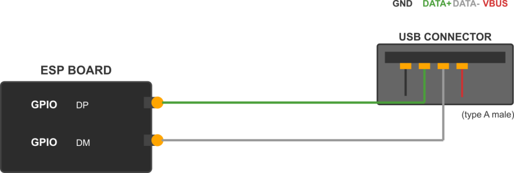
- Connect the ESP32-S2/S3: Use a USB cable to connect the board’s native USB port (not the UART/COM port) to your computer.
- Build: Run the
ESP-IDF: Build your projectcommand in VS Code. - Flash: Run the
ESP-IDF: Flash your projectcommand. You may need to manually put the device into bootloader mode by holding theBOOTbutton, pressing and releasing theRESETbutton, and then releasing theBOOTbutton. - Observe:
- After flashing, reset the board.
- Your computer should detect a new USB device and, after a few seconds, mount a new disk drive.
- The drive will be unformatted. Your operating system will prompt you to format it. Choose a simple filesystem like FAT or FAT32 with the default allocation unit size.
- Once formatted, you can drag and drop files onto the drive. Observe the log output in the ESP-IDF monitor to see the
READ10andWRITE10commands being handled. - You can copy files from the drive back to your computer.
Common Mistakes & Troubleshooting Tips
| Mistake / Issue | Symptom(s) | Troubleshooting / Solution |
|---|---|---|
| Wrong USB Port | Device not detected by PC. Only the serial port (COM/tty) appears. No “new disk” notification. | Ensure you are connected to the native USB-OTG port on the ESP32-S2/S3 board, often labeled USB or OTG. The UART/PROG port is for flashing only. Also, verify you are using a data-capable USB cable, not a charge-only one. |
| Incorrect ESP32 Variant | Code fails to build with errors about missing USB or OTG definitions. Or, code builds but does nothing on an unsupported board. | This project only works on ESP32-S2 and ESP32-S3. The original ESP32, C3, C6, and H2 variants lack the required USB-OTG hardware peripheral. Check your board and ensure the correct target is set in the ESP-IDF configuration. |
| Disk is Read-Only / Format Fails | PC detects the drive but reports it as read-only. Attempting to format the drive results in an error. Log shows WRITE10 calls but files don’t save. | This is a classic sign of a faulty tud_msc_write10_cb implementation. The most common cause is forgetting to erase flash memory before writing.
Solution: Call esp_partition_erase_range() before esp_partition_write(). Flash can only change bits from 1 to 0, so an erase (setting bits to 1) is mandatory first. |
| Partition Not Found | Application fails to start. Log shows an error like “Failed to find storage partition”. | The name in your code does not match the name in your partition CSV file.
1. Check partitions.csv: storage, data, spiffs, , 64K, 2. Check C code: esp_partition_find_first(…, “storage“); The names must be an exact match. Also ensure the CSV file is in the project root. |
| Data Corruption | Files can be written, but when read back they are garbled or incorrect. Small files might work, but larger ones fail. | This often relates to memory alignment. The esp_partition_write function may require the address and buffer size to be aligned to a certain boundary (e.g., 4KB flash sector size). The example code simplifies this, but in a real application, you may need an intermediate buffer to handle writes that are not perfectly aligned. |
Exercises
- Customize Device Identity: Modify the
tud_msc_inquiry_cbcallback to change the Vendor ID, Product ID, and Revision strings to your own custom values. Re-flash the device and check the new identity in your operating system’s device manager. - Implement Write Protection: Add a global boolean variable, e.g.,
g_write_protected. In thetud_msc_scsi_cbcallback, handle theSCSI_CMD_MODE_SENSE_6command to report the write-protect status based on this variable. In thetud_msc_write10_cbcallback, ifg_write_protectedis true, refuse the write operation and return an error. Add a physical button to the ESP32 to toggle this variable, creating a hardware write-protect switch. - Use PSRAM as a RAM Disk: For ESP32-S2/S3 variants that have PSRAM, modify the project to use a section of PSRAM as the storage backend instead of the flash partition. This will create a much faster but volatile disk (its contents will be lost on reset). You will need to replace
esp_partition_read/writecalls withmemcpyto and from a pointer to the PSRAM region. This demonstrates the abstraction of the storage layer.
Summary
- The USB Mass Storage Class (MSC) allows an embedded device to appear as a standard disk drive to a host computer.
- Only the ESP32-S2 and ESP32-S3 have the necessary USB-OTG peripheral to implement custom device classes like MSC.
- The TinyUSB stack, integrated into ESP-IDF, provides the high-level framework for implementing USB devices.
- Implementing an MSC device requires writing callbacks to handle a subset of SCSI commands, primarily
INQUIRY,READ_CAPACITY,READ10, andWRITE10. - A storage backend is required to physically store the data. A dedicated flash partition is a common choice for demonstration and simple applications.
- When using flash, you must erase a memory region before you can write new data to it.
Further Reading
- ESP-IDF TinyUSB Documentation: Espressif TinyUSB Aplication Guide
- TinyUSB Project MSC Example: Official TinyUSB MSC Device Example
- ESP-IDF Partition Table Documentation: Espressif Partition Tables Guide
