
Chapter 241: ULP Sensor Monitoring Applications
Chapter Objectives
By the end of this chapter, you will be able to:
- Interface the ULP with external I2C sensors.
- Implement a bit-banged I2C protocol in both ULP C (RISC-V) and assembly (FSM).
- Design a complete, low-power sensor node that periodically reads data while in deep sleep.
- Read the ESP32‘s internal temperature sensor using the ULP.
- Architect applications where the ULP gathers raw data and the main CPU performs processing and communication.
- Understand the trade-offs and challenges of ULP sensor monitoring with digital protocols.
Introduction
The previous chapters demonstrated how the ULP can monitor simple analog signals from an ADC. This is a powerful capability, but the world of sensors is vast, with many of the most precise and capable sensors (like temperature/humidity sensors, accelerometers, and magnetometers) communicating over digital interfaces like I2C or SPI.
At first glance, this seems like a limitation, as the ULP’s RTC domain does not include hardware I2C or SPI controllers. However, with some clever programming, we can overcome this. This chapter teaches you how to implement these protocols in software—a technique known as “bit-banging”—to unlock the full potential of the ULP. We will build practical, battery-powered sensor applications that can run for months or even years by keeping the power-hungry main cores asleep as much as possible.
graph TD
    subgraph "Deep Sleep State (μA Power Draw)"
        A((RTC Timer Trigger));
        B["<b>ULP Co-Processor</b><br>Runs simple program"];
        C["Bit-bang I2C or<br>read internal sensor"];
        D["Store <b>raw</b> sensor data<br>in RTC Memory"];
        E{"Wakeup Condition Met?<br>(e.g., threshold crossed, or<br>periodic data report needed)"};
    end

    subgraph "Active State (mA Power Draw)"
        F["<b>Main CPU Wakes Up</b>"];
        G["Read <b>raw</b> data from<br>RTC Memory"];
        H["Perform complex calculations<br>(e.g., floating-point conversion)"];
        I["Connect to Wi-Fi/BLE"];
        J["Send processed data<br>to cloud/app"];
        K["Enter Deep Sleep"];
    end

    %% Connections
    A --> B --> C --> D --> E;
    E -- "No" --> A;
    E -- "Yes" --> F;
    F --> G --> H --> I --> J --> K;
    K --> A;

    %% Styling
    classDef sleep-box fill:#DBEAFE,stroke:#1E40AF,color:#1E40AF;
    classDef active-box fill:#FEE2E2,stroke:#991B1B,color:#991B1B;
    classDef process-node fill:#FFFFFF,stroke:#4B5563;
    classDef decision-node fill:#FEF3C7,stroke:#D97706,color:#92400E;

    class B,C,D process-node;
    class F,G,H,I,J,K process-node;
    class E decision-node;
Theory
Interfacing with I2C Sensors
The I2C (Inter-Integrated Circuit) protocol is a popular two-wire serial interface (SDA for data, SCL for clock) used by countless sensors. Since the ULP cannot access the main I2C hardware peripherals, it must replicate the protocol manually.
What is Bit-Banging?
Bit-banging is the technique of using standard general-purpose I/O pins to emulate a serial communication protocol in software. Instead of a hardware peripheral generating the clock signals and managing data lines according to the protocol rules, the processor does it directly by “banging the bits” one by one.
For I2C, the ULP program must:
- Manually pull the SCL line low.
- Set the SDA line high or low for the desired data bit.
- Manually pull the SCL line high, then low again to create a clock pulse.
- Repeat for all bits in a byte.
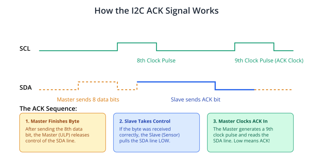
- Generate the correct Start, Stop, and Acknowledge (ACK/NACK) conditions by manipulating SDA and SCL in the correct sequence.
sequenceDiagram
    participant Master
    participant Slave

    Master->>SDA: START Condition (SDA Low while SCL High)

    loop 7 Address Bits
        Master->>SDA: Set Address Bit
        Master->>SCL: Clock Pulse (High -> Low)
    end

    Master->>SDA: Set R/W Bit (0 for Write)
    Master->>SCL: Clock Pulse (High -> Low)

    Slave-->>SDA: ACK (Pulls SDA Low)
    Master->>SCL: Clock Pulse

    loop 8 Data Bits
        Master->>SDA: Set Data Bit
        Master->>SCL: Clock Pulse (High -> Low)
    end

    Slave-->>SDA: ACK (Pulls SDA Low)
    Master->>SCL: Clock Pulse

    Master->>SDA: STOP Condition (SDA High while SCL High)
Challenges of ULP Bit-Banging
- Timing: I2C has specific timing requirements (e.g., minimum clock high/low periods). The ULP runs on the
RTC_FAST_CLKorRTC_SLOW_CLK, which is much slower than the main CPU clock. Your code must insert precise delays usingWAITinstructions (FSM ULP) or calibrated delay loops (RISC-V ULP) to meet the protocol’s timing specifications. Using an oscilloscope to verify your signal integrity is highly recommended. - Code Complexity: Implementing a communication protocol in software, especially in assembly, is more complex and error-prone than using a hardware driver.
Using the Internal Temperature Sensor
In addition to external sensors, many ESP32 variants contain an internal temperature sensor that is part of the RTC domain. This allows the ULP to measure the chip’s die temperature without any external components.
The sensor works by generating a voltage that corresponds to the temperature. The ULP can trigger a measurement and read this raw value from a specific peripheral register. The key steps are:
| Step | Action (Conceptual) | Typical ULP Register(s) Involved (ESP32-S3) |
|---|---|---|
| 1. Power On | Enable power to the temperature sensor circuit. | SENS_SAR_TSENS_CTRL_REG: Set SENS_TSENS_POWER_UP bit. |
| 2. Configure | Set the clock source and output range for the sensor. | SENS_SAR_TSENS_CTRL_REG: Configure SENS_TSENS_CLK_DIV. |
| 3. Trigger | Start a single temperature conversion. | (This is often handled by the same power-on write operation). |
| 4. Wait | Pause execution to allow time for the conversion to complete (typically a few milliseconds). | FSM: wait instruction.RISC-V: Calibrated delay loop. |
| 5. Read Raw Value | Read the 8-bit digital result of the conversion. | SENS_SAR_TSENS_CTRL_REG: Read from the SENS_TSENS_OUT field. |
| 6. Power Off | Disable the sensor to conserve power until the next reading. | SENS_SAR_TSENS_CTRL_REG: Clear SENS_TSENS_POWER_UP bit. |
The raw value does not directly represent degrees Celsius. It must be converted using a calibration formula. Because this often involves floating-point arithmetic, the standard practice is for the ULP to read the raw value and wake the main CPU to perform the final conversion.
Practical Example: ULP I2C Sensor Reading (ESP32-S3)
This example demonstrates how to use the RISC-V ULP on an ESP32-S3 to read temperature from a BME280 sensor via a bit-banged I2C interface.
Hardware Setup:
- An ESP32-S3 development board.
- A BME280 sensor breakout board.
- Connect SCL of the sensor to an RTC GPIO (e.g., GPIO1).
- Connect SDA of the sensor to another RTC GPIO (e.g., GPIO2).
- Connect VCC to 3.3V and GND to GND.
- Crucially, add 4.7kΩ pull-up resistors from both SCL and SDA lines to 3.3V.
1. Project and Component Structure
- Create a new ESP-IDF project for the ESP32-S3.
- Create a ULP component:
components/ulp_bme280. - Inside the component, we will create three files:
ulp_i2c.h: Header for our bit-banging functions.ulp_i2c.c: Implementation of the I2C bit-banging logic.ulp_main.c: The main ULP application that uses the I2C functions to talk to the BME280.
- Don’t forget the component’s
CMakeLists.txtfile (refer to Chapter 239).
2. ULP I2C Bit-Banging Implementation (ulp_i2c.c)
This file contains the low-level functions to create I2C signals.
File: components/ulp_bme280/ulp_i2c.c
#include "ulp_riscv.h"
#include "ulp_riscv_gpio.h"

// I2C Configuration
#define I2C_SCL_PIN GPIO_NUM_1
#define I2C_SDA_PIN GPIO_NUM_2

// Simple delay function for I2C timing
static void i2c_delay(void) {
    // This value needs to be tuned based on the ULP clock speed
    // and the desired I2C frequency (e.g., 100kHz).
    // A simple busy-wait loop.
    for (volatile int i = 0; i < 20; i++);
}

void i2c_init(void) {
    ulp_riscv_gpio_init(I2C_SCL_PIN);
    ulp_riscv_gpio_init(I2C_SDA_PIN);
    ulp_riscv_gpio_set_direction(I2C_SCL_PIN, RTC_GPIO_MODE_INPUT_OUTPUT);
    ulp_riscv_gpio_set_direction(I2C_SDA_PIN, RTC_GPIO_MODE_INPUT_OUTPUT);
}

void i2c_start(void) {
    ulp_riscv_gpio_set_level(I2C_SDA_PIN, 1);
    i2c_delay();
    ulp_riscv_gpio_set_level(I2C_SCL_PIN, 1);
    i2c_delay();
    ulp_riscv_gpio_set_level(I2C_SDA_PIN, 0);
    i2c_delay();
    ulp_riscv_gpio_set_level(I2C_SCL_PIN, 0);
    i2c_delay();
}

void i2c_stop(void) {
    ulp_riscv_gpio_set_level(I2C_SDA_PIN, 0);
    i2c_delay();
    ulp_riscv_gpio_set_level(I2C_SCL_PIN, 1);
    i2c_delay();
    ulp_riscv_gpio_set_level(I2C_SDA_PIN, 1);
    i2c_delay();
}

// Returns 0 on ACK, 1 on NACK
int i2c_write_byte(uint8_t data) {
    for (int i = 0; i < 8; i++) {
        ulp_riscv_gpio_set_level(I2C_SDA_PIN, (data & 0x80) ? 1 : 0);
        data <<= 1;
        i2c_delay();
        ulp_riscv_gpio_set_level(I2C_SCL_PIN, 1);
        i2c_delay();
        ulp_riscv_gpio_set_level(I2C_SCL_PIN, 0);
    }
    // Read ACK/NACK
    ulp_riscv_gpio_set_direction(I2C_SDA_PIN, RTC_GPIO_MODE_INPUT_ONLY);
    i2c_delay();
    ulp_riscv_gpio_set_level(I2C_SCL_PIN, 1);
    i2c_delay();
    int ack = ulp_riscv_gpio_get_level(I2C_SDA_PIN);
    ulp_riscv_gpio_set_level(I2C_SCL_PIN, 0);
    ulp_riscv_gpio_set_direction(I2C_SDA_PIN, RTC_GPIO_MODE_INPUT_OUTPUT);
    return ack;
}
// Add i2c_read_byte() similarly
Tip: Fully implementing the
i2c_read_bytefunction is left as an exercise for the reader, as it follows a similar pattern but involves sending ACKs from the master.
3. ULP Main Application (ulp_main.c)
This file orchestrates the communication with the BME280.
File: components/ulp_bme280/ulp_main.c
#include "ulp_riscv.h"
#include "ulp_i2c.h" // Our bit-banging library

// BME280 Definitions
#define BME280_I2C_ADDRESS  0x76
#define BME280_REG_CTRL_MEAS 0xF4
#define BME280_REG_TEMP_MSB  0xFA

RTC_SLOW_ATTR uint32_t raw_temp_data = 0;

int main(void) {
    i2c_init();

    // --- Write to BME280 to request a temperature measurement ---
    i2c_start();
    // Send address with write bit
    i2c_write_byte(BME280_I2C_ADDRESS << 1 | 0);
    // Send register address for measurement control
    i2c_write_byte(BME280_REG_CTRL_MEAS);
    // Set forced mode, 1x oversampling
    i2c_write_byte(0x25);
    i2c_stop();

    // A real implementation would wait here for the measurement to complete.
    // We will assume it's ready by the next ULP wakeup.

    // --- Read the temperature data from the BME280 ---
    i2c_start();
    i2c_write_byte(BME280_I2C_ADDRESS << 1 | 0); // Address + Write
    i2c_write_byte(BME280_REG_TEMP_MSB);        // Point to temperature MSB register
    i2c_start(); // Repeated start
    i2c_write_byte(BME280_I2C_ADDRESS << 1 | 1); // Address + Read

    // uint8_t msb = i2c_read_byte(SEND_ACK);
    // uint8_t lsb = i2c_read_byte(SEND_ACK);
    // uint8_t xlsb = i2c_read_byte(SEND_NACK);
    // For simplicity, we skip the read implementation details.

    i2c_stop();

    // raw_temp_data = (msb << 12) | (lsb << 4) | (xlsb >> 4);

    // For this example, let's just use a dummy value
    raw_temp_data = 12345;

    // Wake the main processor
    ulp_riscv_wakeup_main_processor();

    return 0; // Halt
}
4. Main CPU Application (main/main.c)
This code starts the ULP and processes the data upon wakeup.
// In main/main.c
#include "esp_sleep.h"
#include "esp_log.h"
#include "ulp_riscv.h"
#include "ulp_main.h" // Generated header

extern RTC_SLOW_ATTR uint32_t raw_temp_data;

void app_main(void) {
    if (esp_sleep_get_wakeup_cause() == ESP_SLEEP_WAKEUP_ULP) {
        ESP_LOGI("MainCPU", "Woken up by ULP!");
        ESP_LOGI("MainCPU", "Raw temperature data from BME280: %" PRIu32, raw_temp_data);
        // Add BME280 compensation formulas here to convert raw_temp_data to Celsius
    } else {
        ESP_LOGI("MainCPU", "Starting ULP I2C application");
        // Load and run the ULP program (see Chapter 239 for details)
        // ...
    }

    ESP_LOGI("MainCPU", "Entering deep sleep...");
    esp_deep_sleep_start();
}
Variant Notes
- ESP32 (FSM ULP): Implementing I2C bit-banging in FSM assembly is significantly more challenging. You must use
RD_REGandWR_REGto toggle GPIOs andWAITfor timing. The program structure is less intuitive, but it is possible and highly power-efficient.
| Aspect | RISC-V ULP (C Language) | FSM ULP (Assembly) |
|---|---|---|
| GPIO Control | Abstracted function calls:ulp_riscv_gpio_set_level(pin, 1); |
Direct register manipulation:WR_REG(RTC_GPIO_OUT_W1TS_REG, ...); |
| Timing/Delays | Software loops:for (volatile int i=0; i |
Dedicated hardware instruction:wait 100 // Wait 100 cycles |
| Logic/Flow | Standard C constructs (loops, functions, if/else). Easy to structure. | Manual jumps and labels (JUMP, JUMPR). Requires careful planning. |
| Code Readability | High. Logic is self-documenting. | Low. Requires heavy commenting to understand the protocol flow. |
| Development Effort | Moderate. The main challenge is getting the timing right. | Very high. Requires deep knowledge of both I2C and FSM assembly. Prone to errors. |
- Internal Temperature Sensor: The register addresses and conversion formulas for the internal sensor vary by chip. For the ESP32, you would use
SENS_SAR_TSENS_CTRL_REGand related registers. For the ESP32-S3, it'sSENS_SAR_TSENS_CTRL_REGas well, but with slightly different bitfields. Always consult the Technical Reference Manual for your specific chip. - No ULP (ESP32-C3): This type of periodic sensor monitoring is not possible in deep sleep. The entire chip would need to wake up via an RTC timer to perform the I2C communication.
Common Mistakes & Troubleshooting Tips
| Symptom | Possible Cause(s) | Verification & Solution |
|---|---|---|
| No ACK on Address Byte (Sensor never pulls SDA low after you send its address) |
1. Wrong I2C address. 2. Missing pull-up resistors. 3. Incorrect wiring (SDA/SCL swapped). 4. Sensor is not powered or is damaged. |
1. Check the sensor's datasheet for the correct 7-bit address. Confirm you are shifting it correctly (addr << 1).2. Verify 4.7kΩ pull-up resistors are on SCL and SDA to 3.3V. 3. Double-check your wiring against the hardware diagram. 4. Use a multimeter to check for 3.3V at the sensor's VCC pin. |
| No ACK on Data Byte (Sensor ACKs the address, but not the following data bytes) |
1. Invalid command or writing to a read-only register. 2. Incorrect bit-banging timing. 3. Logic error in the ULP program. |
1. Consult the sensor datasheet. Ensure the register you are writing to is writable and the data value is valid. 2. Use an oscilloscope to verify your SCL clock speed. Slow it down by increasing the delay between pin toggles. 3. Manually trace your bit-banging logic to ensure start/stop conditions are correct. |
| Receiving Data is all 1s (0xFF) (When trying to read from the sensor) |
1. Master (ULP) is not releasing the SDA line. 2. Missing pull-up resistors. |
1. During the read phase and ACK clock, the Master must stop driving the SDA pin and configure it as an input to allow the Slave to control it. Ensure your code does this. 2. Without pull-ups, the floating line will often be read as high. |
| NACK is correctly received, but unexpected (e.g., at the end of a read sequence) |
1. This is often correct behavior. 2. Forgetting to send a Repeated Start. |
1. The Master should send a NACK after reading the final byte from a slave to signal the end of the read transaction. This is normal. 2. To write a register address and then immediately read from it, you must use a Repeated Start condition, not a Stop then Start.
|
Exercises
- Finish the I2C Reader: Complete the
i2c_read_byte()function in theulp_i2c.clibrary and modify the main ULP program to read the actual BME280 temperature and store it. - Internal Temperature Alert: Write a ULP program (for any ULP-capable chip) that reads the internal temperature sensor. If the raw value exceeds a certain threshold, wake the main CPU.
- Low Battery & Sensor Combo: Create an application that uses the ULP to perform two tasks in sequence: first, read an external I2C sensor; second, read the battery voltage via an ADC channel. The ULP should wake the main CPU if either the sensor value crosses its threshold OR the battery voltage drops below a critical level.
Summary
- The ULP can communicate with complex digital sensors using bit-banged protocols like I2C.
- Programming this in C on the RISC-V ULP is far simpler than using assembly on the FSM ULP.
- Correct timing and hardware setup (especially pull-up resistors) are critical for successful bit-banged communication.
- The ULP can also access on-chip peripherals like the internal temperature sensor.
- A powerful design pattern for ultra-low-power applications is: ULP gathers raw data, Main CPU processes it. This minimizes the time the power-hungry main cores are active.
Further Reading
- ESP-IDF ULP I2C Example: https://github.com/espressif/esp-idf/tree/master/examples/system/ulp_riscv/i2c
- ESP32-S3 Technical Reference Manual: https://www.espressif.com/sites/default/files/documentation/esp32-s3_technical_reference_manual_en.pdf (See chapters on RTC and Temperature Sensor).
- I2C Protocol Specification: https://www.nxp.com/docs/en/user-guide/UM10204.pdf
