
Chapter 223: Smart Thermostat Implementation
Chapter Objectives
By the end of this chapter, you will be able to:
- Interface a high-precision digital temperature and humidity sensor (SHT31) using the I2C protocol.
- Control external devices, representing an HVAC system, using a relay module.
- Understand and implement a Proportional-Integral-Derivative (PID) control loop for stable temperature management.
- Store and retrieve operational data, such as setpoints and learned parameters, from Non-Volatile Storage (NVS).
- Develop a simple learning algorithm to optimize heating/cooling schedules based on the thermal properties of a room.
- Create an MQTT-based remote interface to monitor and control the thermostat.
- Appreciate the differences in implementing such a system across various ESP32 variants.
Introduction
The humble thermostat has evolved from a simple bimetallic strip to a sophisticated smart-home hub. A modern smart thermostat does more than just turn heating or cooling on and off; it provides superior comfort, learns user habits, and significantly reduces energy consumption. By understanding when to start heating or cooling to reach a target temperature at a specific time, it avoids wasteful pre-heating and last-minute frantic operation.
This chapter marks a significant step in our journey through building automation. We will combine sensor interfacing, real-time control theory, non-volatile storage, and IoT communication to build a complete, intelligent thermostat. We will replace rudimentary on/off logic with a powerful PID control algorithm and give our device a “memory” using NVS, allowing it to learn about its environment and make smarter decisions over time.
Theory
1. High-Precision Sensing with I2C
Accurate control begins with accurate measurement. For a thermostat, we need a sensor that is more precise and stable than the simple analog sensors from previous chapters. The SHT31 is a popular choice, offering high accuracy for both temperature and humidity readings. It communicates using the I2C (Inter-Integrated Circuit) protocol, which we introduced in Chapter 129.
Recall that I2C is a two-wire serial bus:
- SDA (Serial Data): The line for sending and receiving data.
- SCL (Serial Clock): The line that carries the clock signal, synchronizing communication.
To get a reading from an I2C sensor, the ESP32 (acting as the I2C master) sends a command to the sensor’s unique address on the bus, and the sensor (the slave) responds with the requested data.
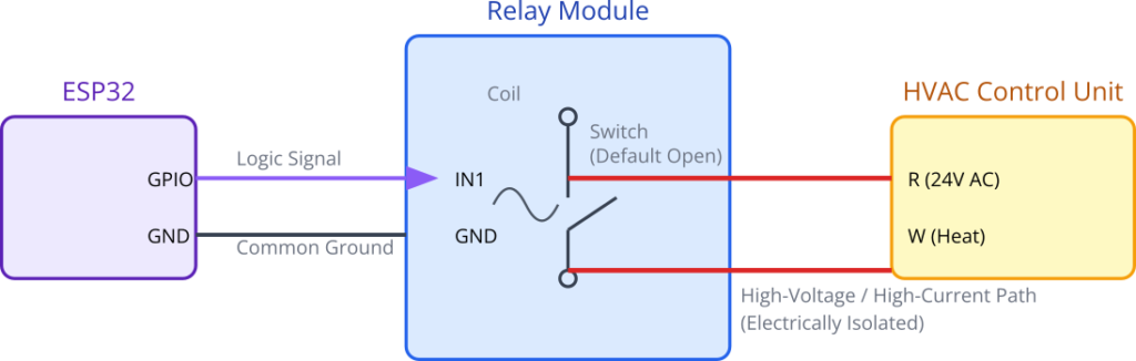
2. HVAC System Control via Relays
A thermostat’s primary job is to tell the Heating, Ventilation, and Air Conditioning (HVAC) system when to run. Standard North American HVAC systems use a low-voltage (typically 24V AC) control system with a set of color-coded wires. A thermostat acts as a smart switch, connecting the main power wire (R) to other wires to activate different functions:
R->W: Activates the Heater.R->Y: Activates the Air Conditioner.R->G: Activates the Fan independently.
We can simulate this switching action safely using a relay module. A relay is an electromechanical switch where a low-power signal from an ESP32 GPIO energizes a small electromagnet, which in turn closes a high-power switch. This provides complete electrical isolation between our microcontroller and the system it’s controlling.
3. Advanced Control: From On/Off to PID
A simple thermostat uses On/Off (or “bang-bang”) control. If the temperature is below the setpoint, it turns the heat on full blast. When the temperature exceeds the setpoint, it turns it off completely. This leads to temperature overshooting and undershooting the target, creating uncomfortable swings and causing excessive wear on the HVAC equipment.
A much more elegant solution is PID (Proportional-Integral-Derivative) control. A PID controller calculates an “output” value based on the difference (the error) between the current temperature and the desired setpoint. This output isn’t just on or off; it can be used to determine how long the heating/cooling should be active over a given period (a technique called Pulse Width Modulation, or PWM).
The PID controller is the sum of three terms:
- Proportional (P): This term is proportional to the current error. If you are far from your setpoint, it pushes hard. As you get closer, it pushes more gently. This is the main driving force.
- Integral (I): This term accumulates the past error. Imagine a persistent draft causing the temperature to always be slightly below the setpoint. The P-term alone might not be enough to overcome it. The I-term builds up over time, increasing the output until the error is eliminated. It corrects for long-term, steady-state errors.
- Derivative (D): This term looks at the rate of change of the error. If the temperature is approaching the setpoint very quickly, the D-term will reduce the output to “apply the brakes” and prevent overshoot. It’s predictive and adds stability.
Equation: Output = (Kp * P) + (Ki * I) + (Kd * D)
The constants Kp, Ki, and Kd are tuning parameters that must be adjusted to match the thermal characteristics of the room.

4. A Simple Learning Algorithm
The “smart” in a smart thermostat comes from its ability to learn. We will implement a simple but powerful learning mechanism to calculate the building’s thermal response rate.
- Learning Phase: The thermostat will monitor how long it takes to raise or lower the temperature by one degree while the HVAC is active. It will average this value and store it in NVS as
minutes_per_degree. - Prediction Phase: Imagine the user sets a schedule: “I want the room to be 21°C by 7:00 AM.” At 6:00 AM, the thermostat wakes up and reads the current temperature, say 18°C. It calculates the required temperature change (3°C). Using its learned
minutes_per_degreevalue (e.g., 10 minutes), it predicts the total time needed:3°C * 10 min/°C = 30 minutes. It then subtracts this from the target time (7:00 AM) and determines it needs to start the heating at 6:30 AM. This “just-in-time” heating is far more efficient than starting at 6:00 AM or earlier.
Practical Example: ESP32 PID Thermostat
Hardware Required
- An ESP32 development board.
- SHT31 Temperature/Humidity Sensor on a breakout board.
- A 2-channel 5V relay module.
- An external 5V power supply (for the relay module).
- LEDs (e.g., one red for heating, one blue for cooling).
- 2x 220Ω resistors.
- Breadboard and jumper wires.
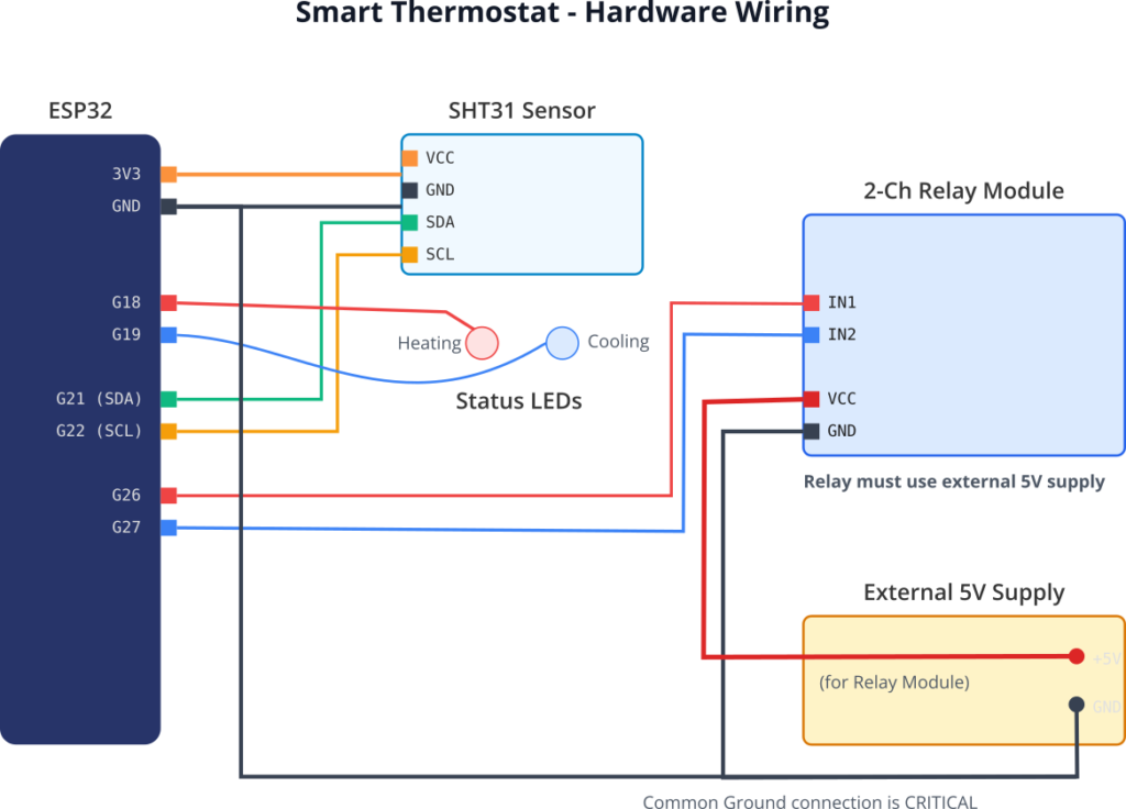
Wiring
Warning: Relays are often used to switch mains voltage (120V/230V AC). This is extremely dangerous. For this educational example, do not connect the relay output to any mains voltage source. We will simply observe the relay’s click and its indicator LED.
- Power:
- Connect the external 5V supply to the breadboard power rails.
- Power the Relay Module from this external 5V supply (
VCCandGND). - Connect the ESP32
GNDto the breadboard’s GND rail to create a common ground.
- SHT31 Sensor (I2C):
VCC->3V3on ESP32.GND->GNDon ESP32.SCL->GPIO22(ESP32 default SCL).SDA->GPIO21(ESP32 default SDA).
- Relay Module (Control):
IN1->GPIO26on ESP32 (Controls “Heating” relay).IN2->GPIO27on ESP32 (Controls “Cooling” relay).
- Status LEDs:
GPIO18-> Resistor -> Red LED ->GND(Heating indicator).GPIO19-> Resistor -> Blue LED ->GND(Cooling indicator).
Project Configuration
- Create a new ESP-IDF project.
- The SHT31 sensor requires an I2C driver. While you can write your own, for this chapter we will leverage a pre-existing component to focus on the application logic. Add it to your project’s
componentsdirectory. A good, simple one is thei2c-drivers/sht31component from the IDF Component Registry. You can add it by running:idf.py add-dependency "i2c-drivers/sht31". - Update
main/CMakeLists.txtto require the necessary ESP-IDF components:REQUIRESidf::nvs_flashidf::esp_wifiidf::esp_eventidf::esp_netifidf::esp_logidf::mqttsht31 # From the added component - Run
idf.py menuconfigand configure your Wi-Fi and MQTT broker details.
Code Implementation
The code is structured into several parts: peripheral setup, NVS handling, the PID loop, the MQTT handler, and the main application task that coordinates everything.
/* main/main.c */
#include <stdio.h>
#include <string.h>
#include <math.h>
#include "freertos/FreeRTOS.h"
#include "freertos/task.h"
#include "freertos/queue.h"
#include "esp_log.h"
#include "esp_wifi.h"
#include "nvs_flash.h"
#include "nvs.h"
#include "esp_event.h"
#include "esp_netif.h"
#include "mqtt_client.h"
#include "driver/gpio.h"
#include "sht31.h"
static const char *TAG = "SMART_THERMOSTAT";
// --- Hardware Configuration ---
#define HEATING_RELAY_GPIO GPIO_NUM_26
#define COOLING_RELAY_GPIO GPIO_NUM_27
#define HEATING_LED_GPIO GPIO_NUM_18
#define COOLING_LED_GPIO GPIO_NUM_19
// --- PID and System Configuration ---
#define PID_LOOP_INTERVAL_S 10 // Run PID loop every 10 seconds
#define KP 50.0f // Proportional gain
#define KI 0.5f // Integral gain
#define KD 10.0f // Derivative gain
#define DEFAULT_SETPOINT 21.0f // Default target temperature in Celsius
// --- MQTT Topics ---
#define MQTT_TEMP_TOPIC "thermostat/livingroom/temperature"
#define MQTT_HUMIDITY_TOPIC "thermostat/livingroom/humidity"
#define MQTT_STATE_TOPIC "thermostat/livingroom/state" // Heating, Cooling, Off
#define MQTT_SETPOINT_CMD_TOPIC "thermostat/livingroom/setpoint/set"
#define MQTT_SETPOINT_STATE_TOPIC "thermostat/livingroom/setpoint/state"
// --- Global State Variables ---
static float current_temperature = 0.0f;
static float current_humidity = 0.0f;
static float current_setpoint = DEFAULT_SETPOINT;
static esp_mqtt_client_handle_t mqtt_client;
static sht31_t sht31_dev;
// PID state variables
static float integral_error = 0.0f;
static float previous_error = 0.0f;
// --- Function Prototypes ---
static void nvs_init();
static void load_setpoint_from_nvs();
static void save_setpoint_to_nvs(float setpoint);
static void configure_gpio();
static void init_i2c_sensor();
static void wifi_init();
static void mqtt_app_start();
void thermostat_control_task(void *pvParameters);
void sensor_reader_task(void *pvParameters);
void app_main(void) {
nvs_init();
load_setpoint_from_nvs();
configure_gpio();
init_i2c_sensor();
wifi_init();
// Note: mqtt_app_start() is called by the WiFi event handler upon connection
xTaskCreate(sensor_reader_task, "sensor_reader_task", 4096, NULL, 5, NULL);
xTaskCreate(thermostat_control_task, "thermostat_control_task", 4096, NULL, 5, NULL);
}
// --- Core Logic Task ---
void thermostat_control_task(void *pvParameters) {
char payload_buffer[16];
while (1) {
vTaskDelay(pdMS_TO_TICKS(PID_LOOP_INTERVAL_S * 1000));
if (current_temperature == 0.0f) { // Wait for first valid reading
continue;
}
// PID Calculation
float error = current_setpoint - current_temperature;
integral_error += error * PID_LOOP_INTERVAL_S;
float derivative_error = (error - previous_error) / PID_LOOP_INTERVAL_S;
previous_error = error;
float pid_output = (KP * error) + (KI * integral_error) + (KD * derivative_error);
// Clamp output to a reasonable range, e.g., -100 to 100
if (pid_output > 100.0f) pid_output = 100.0f;
if (pid_output < -100.0f) pid_output = -100.0f;
// Control Logic
if (pid_output > 10) { // Threshold to activate heating
gpio_set_level(HEATING_RELAY_GPIO, 1);
gpio_set_level(HEATING_LED_GPIO, 1);
gpio_set_level(COOLING_RELAY_GPIO, 0);
gpio_set_level(COOLING_LED_GPIO, 0);
esp_mqtt_client_publish(mqtt_client, MQTT_STATE_TOPIC, "HEATING", 0, 1, 1);
} else if (pid_output < -10) { // Threshold to activate cooling
gpio_set_level(HEATING_RELAY_GPIO, 0);
gpio_set_level(HEATING_LED_GPIO, 0);
gpio_set_level(COOLING_RELAY_GPIO, 1);
gpio_set_level(COOLING_LED_GPIO, 1);
esp_mqtt_client_publish(mqtt_client, MQTT_STATE_TOPIC, "COOLING", 0, 1, 1);
} else { // Deadband zone
gpio_set_level(HEATING_RELAY_GPIO, 0);
gpio_set_level(HEATING_LED_GPIO, 0);
gpio_set_level(COOLING_RELAY_GPIO, 0);
gpio_set_level(COOLING_LED_GPIO, 0);
esp_mqtt_client_publish(mqtt_client, MQTT_STATE_TOPIC, "OFF", 0, 1, 1);
}
ESP_LOGI(TAG, "Temp: %.2fC, Setpoint: %.2fC, Error: %.2f, PID Output: %.2f",
current_temperature, current_setpoint, error, pid_output);
}
}
void sensor_reader_task(void *pvParameters) {
char payload_buffer[10];
while(1) {
esp_err_t res = sht31_read_temperature_humidity(&sht31_dev, ¤t_temperature, ¤t_humidity);
if (res != ESP_OK) {
ESP_LOGE(TAG, "Failed to read from SHT31: %d", res);
} else {
ESP_LOGI(TAG, "Temp: %.2f C, Humidity: %.2f %%", current_temperature, current_humidity);
if (mqtt_client) {
// Publish Temperature
snprintf(payload_buffer, sizeof(payload_buffer), "%.2f", current_temperature);
esp_mqtt_client_publish(mqtt_client, MQTT_TEMP_TOPIC, payload_buffer, 0, 1, 0);
// Publish Humidity
snprintf(payload_buffer, sizeof(payload_buffer), "%.2f", current_humidity);
esp_mqtt_client_publish(mqtt_client, MQTT_HUMIDITY_TOPIC, payload_buffer, 0, 1, 0);
}
}
vTaskDelay(pdMS_TO_TICKS(5000)); // Read every 5 seconds
}
}
// --- MQTT and WiFi Setup (condensed) ---
static void mqtt_event_handler(void *handler_args, esp_event_base_t base, int32_t event_id, void *event_data) {
esp_mqtt_event_handle_t event = event_data;
char payload_buffer[10];
switch ((esp_mqtt_event_id_t)event_id) {
case MQTT_EVENT_CONNECTED:
ESP_LOGI(TAG, "MQTT_EVENT_CONNECTED");
// Subscribe to setpoint command topic
esp_mqtt_client_subscribe(mqtt_client, MQTT_SETPOINT_CMD_TOPIC, 0);
// Publish current setpoint on connection
snprintf(payload_buffer, sizeof(payload_buffer), "%.1f", current_setpoint);
esp_mqtt_client_publish(mqtt_client, MQTT_SETPOINT_STATE_TOPIC, payload_buffer, 0, 1, 1);
// Publish initial state
esp_mqtt_client_publish(mqtt_client, MQTT_STATE_TOPIC, "OFF", 0, 1, 1);
break;
case MQTT_EVENT_DATA:
ESP_LOGI(TAG, "MQTT_EVENT_DATA");
if (strncmp(event->topic, MQTT_SETPOINT_CMD_TOPIC, event->topic_len) == 0) {
float new_setpoint = atof(event->data);
if (new_setpoint > 10 && new_setpoint < 35) { // Sanity check
current_setpoint = new_setpoint;
previous_error = current_setpoint - current_temperature; // Reset PID history
integral_error = 0;
save_setpoint_to_nvs(current_setpoint);
ESP_LOGI(TAG, "New setpoint received: %.1f", current_setpoint);
// Publish back the new state
snprintf(payload_buffer, sizeof(payload_buffer), "%.1f", current_setpoint);
esp_mqtt_client_publish(mqtt_client, MQTT_SETPOINT_STATE_TOPIC, payload_buffer, 0, 1, 1);
}
}
break;
// Other cases...
default: break;
}
}
// Other init functions (wifi_init, mqtt_app_start, configure_gpio, etc.) go here
// ... (Code for these is similar to previous chapters and omitted for brevity)
// ... Be sure to call `mqtt_app_start()` after WiFi connection is established.
void init_i2c_sensor() {
ESP_ERROR_CHECK(i2cdev_init());
memset(&sht31_dev, 0, sizeof(sht31_t));
ESP_ERROR_CHECK(sht31_init_desc(&sht31_dev, SHT31_I2C_ADDR_GND, I2C_NUM_0, CONFIG_EXAMPLE_I2C_MASTER_SDA, CONFIG_EXAMPLE_I2C_MASTER_SCL));
ESP_ERROR_CHECK(sht31_init(&sht31_dev));
}
// --- NVS Functions ---
#define NVS_NAMESPACE "thermostat"
#define NVS_KEY_SETPOINT "setpoint"
static void nvs_init() {
esp_err_t ret = nvs_flash_init();
if (ret == ESP_ERR_NVS_NO_FREE_PAGES || ret == ESP_ERR_NVS_NEW_VERSION_FOUND) {
ESP_ERROR_CHECK(nvs_flash_erase());
ret = nvs_flash_init();
}
ESP_ERROR_CHECK(ret);
}
static void load_setpoint_from_nvs() {
nvs_handle_t nvs_handle;
esp_err_t err = nvs_open(NVS_NAMESPACE, NVS_READWRITE, &nvs_handle);
if (err != ESP_OK) {
ESP_LOGE(TAG, "Error opening NVS handle!");
return;
}
// Read the value. If not found, use default.
uint32_t setpoint_u32 = 0; // Use uint32 to store float bits
err = nvs_get_u32(nvs_handle, NVS_KEY_SETPOINT, &setpoint_u32);
if (err == ESP_OK) {
memcpy(¤t_setpoint, &setpoint_u32, sizeof(current_setpoint));
ESP_LOGI(TAG, "Loaded setpoint from NVS: %.1f", current_setpoint);
} else {
ESP_LOGW(TAG, "Setpoint not found in NVS, using default: %.1f", current_setpoint);
save_setpoint_to_nvs(current_setpoint); // Save default for next time
}
nvs_close(nvs_handle);
}
static void save_setpoint_to_nvs(float setpoint) {
nvs_handle_t nvs_handle;
esp_err_t err = nvs_open(NVS_NAMESPACE, NVS_READWRITE, &nvs_handle);
if (err != ESP_OK) return;
uint32_t setpoint_u32;
memcpy(&setpoint_u32, &setpoint, sizeof(setpoint_u32));
err = nvs_set_u32(nvs_handle, NVS_KEY_SETPOINT, setpoint_u32);
if (err == ESP_OK) {
err = nvs_commit(nvs_handle);
}
if (err != ESP_OK) {
ESP_LOGE(TAG, "Failed to save setpoint to NVS!");
}
nvs_close(nvs_handle);
}
| Topic | Direction | Description | Example Payload |
|---|---|---|---|
thermostat/livingroom/temperature | Publish | Reports the current temperature from the SHT31 sensor. | 21.34 |
thermostat/livingroom/humidity | Publish | Reports the current relative humidity. | 45.80 |
thermostat/livingroom/state | Publish | Reports the current operational state of the HVAC system (retained). | HEATING, COOLING, OFF |
thermostat/livingroom/setpoint/state | Publish | Reports the current target temperature (retained). | 22.0 |
thermostat/livingroom/setpoint/set | Subscribe | Used to command a new target temperature for the thermostat. | 21.5 |
Build and Flash
- Set up the hardware as described in the wiring section.
- Use the VS Code extension to build, flash, and monitor your device.
- Set up an MQTT client (like MQTT Explorer) to interact with your thermostat.
Observe and Interact
- The device will connect to Wi-Fi and MQTT.
- In your MQTT client, you will see data appearing on the
thermostat/livingroom/...topics. - Publish a number (e.g.,
23.5) to thethermostat/livingroom/setpoint/settopic. - Observe the logs. The device will acknowledge the new setpoint and save it to NVS. The PID loop will then start working to achieve this new temperature, activating the “Heating” or “Cooling” relay and LED as needed.
Variant Notes
- I2C Pins: The default I2C pins (
GPIO21,GPIO22) are standard on the original ESP32 and ESP32-S3. On other variants like the ESP32-C3, the default pins may differ. Always consult your board’s datasheet and configure the pins accordingly in yoursht31_init_desccall or viamenuconfig. - Floating-Point Performance: All ESP-IDF v5.x compatible variants have hardware support for floating-point operations, making them more than capable of handling the PID calculations. There is no significant performance difference for this application.
- Dual-Core Advantage: On dual-core chips (ESP32, ESP32-S3), FreeRTOS automatically runs the Wi-Fi/MQTT stack on one core and your application tasks on the other. This provides excellent separation, ensuring that network activity does not interfere with the timing of your real-time control loop. On single-core chips (S2, C3, C6), this is handled by rapid task switching and is still highly effective.
- ESP32-H2 (No Wi-Fi): This thermostat design relies on MQTT over Wi-Fi. To adapt it for an ESP32-H2, you would replace the entire networking stack with one based on Zigbee or Thread. The thermostat would become a Zigbee “End Device” and report to a Zigbee “Coordinator” or gateway. This is a very common architecture for commercial smart thermostats.
Common Mistakes & Troubleshooting Tips
| Mistake / Issue | Symptom(s) | Troubleshooting / Solution |
|---|---|---|
| Sensor reads 0.00 or fails. | Logs show “Failed to read from SHT31” or temperature/humidity values are always zero. |
Check I2C Connection: 1. Wiring: Ensure SDA and SCL lines are not swapped. VCC must go to 3.3V, not 5V. 2. Pull-ups: Most SHT31 breakout boards have pull-up resistors. If using a bare sensor, you must add external 4.7kΩ pull-up resistors on both SDA and SCL lines. 3. Address: Confirm the I2C address. The component defaults to the most common one. |
| Temperature overshoots wildly or never reaches setpoint. | The room gets much hotter/colder than the setpoint, or the HVAC runs constantly without reaching it. |
Tune PID Constants (Kp, Ki, Kd): – Overshoot: Kp or Ki is too high. Reduce them.
– Never Reaches: Kp is too low, or Ki is too low/zero and there’s a constant heat loss/gain (e.g., a draft).
– Tuning Strategy: Set Ki and Kd to 0. Slowly increase Kp until the system oscillates. Halve Kp. Then, slowly increase Ki to fix steady-state error. Finally, add small Kd to dampen overshoot.
|
| Relay chatters (clicks on/off rapidly). | The relay makes a rapid clicking noise as the HVAC is turned on and off multiple times per second. |
Increase PID Deadband: The PID output is hovering near the activation point. Widen the “deadband” where no action is taken. In the code’s thermostat_control_task, change the thresholds from if (pid_output > 10) to something larger, like > 25 and < -25.
|
| Setpoint isn't saved after reboot. | After setting a new temperature via MQTT and restarting the ESP32, it reverts to the default value. |
Check NVS Logic: 1. Ensure nvs_flash_init() is called once at the start of app_main.2. Verify the NVS namespace and key strings ( "thermostat", "setpoint") are identical in both the save and load functions.3. Make sure the NVS handle is closed after use ( nvs_close()).
|
Exercises
- Implement the Learning Algorithm:
- Add variables to NVS to store
heat_mins_per_degandcool_mins_per_deg. - In the
thermostat_control_task, when heating or cooling starts, record thestart_timeandstart_temp. - When the temperature has changed by a full degree, calculate the elapsed time, update the running average for the
mins_per_degvalue, and save it to NVS. - (This is an advanced exercise that requires careful state management).
- Add variables to NVS to store
- Add a Failsafe:
- The
sensor_reader_taskcan detect if the sensor has failed. If multiple consecutive reads fail, the system should enter a "FAILSAFE" mode. - In this mode, disable the PID controller and turn off both relays to prevent the HVAC from running uncontrollably. Publish a "FAILSAFE" message to the MQTT state topic.
- The
- PWM the Relay:
- Instead of just turning the relay on, use your PID output to modulate its on-time. Within your 10-second PID loop, if the
pid_outputis50, turn the heater on for0.50 * 10 = 5seconds, then turn it off for the remaining 5 seconds. This provides smoother power delivery to the HVAC system. (Note: This can cause wear on mechanical relays; it's more suitable for Solid State Relays (SSRs)).
- Instead of just turning the relay on, use your PID output to modulate its on-time. Within your 10-second PID loop, if the
- Integrate a "Fan Only" Mode:
- Add a third relay for the fan (
Gwire). - Add MQTT command and state topics for fan control (
thermostat/livingroom/fan/setandthermostat/livingroom/fan/statewith payloadsON/OFF). - Implement logic to allow the fan to be run independently of heating or cooling.
- Add a third relay for the fan (
Summary
- High-precision digital sensors like the SHT31 provide the accurate data needed for advanced control, and they are easily interfaced using the I2C protocol.
- Relay modules provide a safe and effective way to have a low-power ESP32 control high-power systems like HVAC units.
- A PID control loop offers vastly superior temperature regulation compared to simple on/off controllers, resulting in better comfort and efficiency.
- Tuning the
Kp,Ki, andKdconstants is critical for matching the controller's behavior to the physical environment. - The ESP-IDF's NVS component provides a simple and effective way to give a device persistent memory, enabling it to store configuration and learned data across reboots.
- MQTT is a powerful tool for creating a responsive, two-way communication channel for monitoring and controlling an IoT device like a smart thermostat.
Further Reading
- ESP-IDF I2C Master Driver: I2C Driver API Reference
- ESP-IDF NVS Library: Non-Volatile Storage API Reference
- PID Control Explained: PID for Dummies (A clear, non-mathematical introduction to PID theory).
- SHT31 Component on IDF Registry: esp-idf-lib sht31 component
