
Chapter 194: SERCOS III Protocol Integration
Chapter Objectives
By the end of this chapter, you will be able to:
- Understand the fundamental principles and purpose of the SERCOS III protocol.
- Describe the key characteristics of SERCOS III, including its Ethernet basis, real-time capabilities, and synchronization methods.
- Outline the basic architecture of a SERCOS III network, including masters and slaves.
- Explain the concept of SERCOS III communication cycles and telegrams.
- Recognize that direct implementation of a SERCOS III master or slave stack on an ESP32 is not practical due to its performance demands.
- Understand architectural approaches for an ESP32 to interact with a SERCOS III network, typically through a gateway or by communicating with a SERCOS III master controller.
- Identify common challenges when considering ESP32 integration with SERCOS III systems.
Introduction
In the world of high-performance automation, particularly in motion control applications like robotics, CNC machining, and packaging machines, precise synchronization and deterministic communication are absolutely critical. SERCOS (Serial Real-time Communication System) is a globally standardized digital interface designed to meet these demanding requirements. SERCOS III, the third generation, leverages standard Ethernet to provide a powerful, high-speed, real-time communication solution.
SERCOS III ensures that all devices in a motion control system (drives, I/O modules, controllers) operate in perfect synchrony, enabling complex, coordinated movements with high precision. It achieves this through very short cycle times, low jitter, and robust error handling.
Due to these stringent real-time demands and the complexity of the protocol stack, implementing a full SERCOS III master or slave directly on a general-purpose microcontroller like the ESP32 is typically not feasible. SERCOS III interfaces usually rely on dedicated hardware, such as FPGAs (Field-Programmable Gate Arrays) or ASICs (Application-Specific Integrated Circuits), to handle the time-critical aspects of the protocol.
Therefore, this chapter will focus on providing a solid understanding of the SERCOS III protocol itself. We will then explore how an ESP32 might be integrated into a larger system that utilizes SERCOS III, for instance, by acting as a human-machine interface (HMI), a data logger, a configuration tool, or a supervisory controller that communicates with a dedicated SERCOS III master (e.g., an industrial PC or PLC) over standard network protocols.
Theory
What is SERCOS?
SERCOS stands for SErial Real-time COmmunication System. It is an open, IEC-standardized (IEC 61491) digital interface optimized for communication between control systems, motion controllers, drives, and I/O devices.
- Evolution:
- SERCOS I (1987): Optical fiber based, focused on high-performance servo drive communication.
- SERCOS II (1999): Enhanced SERCOS I with more data types and improved diagnostics. Still optical fiber.
- SERCOS III (2003): The current generation, based on standard Ethernet (IEEE 802.3). It combines the real-time performance of previous generations with the flexibility and ubiquity of Ethernet.
Key Characteristics of SERCOS III
- Ethernet-Based: Utilizes standard 100 Mbit/s or 1 Gbit/s full-duplex Ethernet. This allows for standard network components (cables, switches, network interface cards if used for non-real-time traffic) to be leveraged.
- Real-Time Determinism: Achieves very short cycle times (down to 31.25 µs) with extremely low jitter (typically < 1 µs). This is crucial for precise synchronization of multiple axes in motion control.
- Collision-Free Access: Employs a time-slot mechanism to avoid data collisions on the Ethernet network for real-time data.
- Synchronization: Utilizes a highly accurate synchronization mechanism, often based on or compatible with IEEE 1588 Precision Time Protocol (PTP), to ensure all network participants share a common sense of time.
- Cyclic and Acyclic Data:
- Cyclic Data: Time-critical data (e.g., setpoints, actual positions, status words) are exchanged in deterministic, fixed-cycle telegrams (MDT and AT).
- Acyclic Data: Less time-critical data (e.g., parameters, diagnostics, configuration) are exchanged via a non-real-time channel, often using standard IP-based protocols (like TCP/IP or UDP/IP) encapsulated within SERCOS III frames or in parallel.
- Safety Integration: SERCOS supports functional safety concepts (CIP Safety on SERCOS), allowing safety-related data to be transmitted over the same network as standard control data.
- Open Standard: Managed by SERCOS International e.V.
SERCOS III Architecture
A SERCOS III network typically consists of:
- SERCOS III Master:
- The central controller of the SERCOS III network segment.
- Manages the communication cycle, synchronization, and data exchange with all connected slave devices.
- Often implemented in high-performance PLCs, industrial PCs, or dedicated motion controllers.
- There is only one active master per SERCOS III ring or line segment.
- SERCOS III Slaves:
- Devices that respond to the master (e.g., servo drives, frequency converters, I/O modules, sensors, actuators).
- Receive setpoints and control commands from the master.
- Send actual values, status, and diagnostic information back to the master.
- Each slave has a unique address.
- Network Topology:
- Line Topology: Devices are daisy-chained. Each SERCOS III device typically has two Ethernet ports acting as an integrated 2-port switch. This allows for simple wiring and reduces the need for external switches in many cases.
- Ring Topology: Connecting the last device in a line back to the master (or a switch connected to the master) creates a ring. This provides media redundancy. If a cable breaks, communication can continue via the other direction of the ring.
- Star or tree topologies are also possible using Ethernet switches, but care must be taken to ensure real-time performance if switches are in the real-time path.
%%{ init: { 'theme': 'base', 'themeVariables': { 'fontFamily': 'Open Sans' } } }%%
graph TB
    subgraph SERCOS III Network
        subgraph Line Topology
            direction LR
            M1[("<b>Master</b>")]:::primary
            S1["Slave 1<br>(Drive)"]:::process
            S2["Slave 2<br>(Drive)"]:::process
            S3["Slave 3<br>(I/O)"]:::process

            M1 -- "Port 1 --> Port 2" --> S1
            S1 -- "Port 1 --> Port 2" --> S2
            S2 -- "Port 1 --> Port 2" --> S3
        end

        subgraph "Ring Topology (for Redundancy)"
            direction LR
            M2[("<b>Master</b>")]:::primary
            S4["Slave A<br>(Drive)"]:::process
            S5["Slave B<br>(I/O)"]:::process
            S6["Slave C<br>(Sensor)"]:::process

            M2 -- "Forward Path" --> S4
            S4 -- " " --> S5
            S5 -- " " --> S6
            S6 -- "Return Path" --> M2
        end
    end

    %% Styling
    classDef primary fill:#EDE9FE,stroke:#5B21B6,stroke-width:2px,color:#5B21B6;
    classDef process fill:#DBEAFE,stroke:#2563EB,stroke-width:1px,color:#1E40AF;
SERCOS III Communication Principle
SERCOS III communication is based on a strict cyclic schedule.
- Communication Cycle (Cycle Time, TScyc):
- The master defines a fixed communication cycle time (e.g., 250 µs, 500 µs, 1 ms, 2 ms, 4 ms, etc.).
- All real-time data exchange occurs within these repeating cycles.
- Telegrams: Data is exchanged in Ethernet frames called “telegrams.”
- Master Data Telegram (MDT): Sent by the master at the beginning of each cycle. It contains data (e.g., setpoints, control words) for multiple slaves. Each slave reads its relevant data from the MDT as it passes through.
- Drive Telegram / Acknowledge Telegram (AT): After processing the MDT, each slave sends its data (e.g., actual position, status) back to the master in an AT. Slaves fill their data into the AT as it propagates along the line/ring back towards the master.
- No Collisions: Because of the time-slot nature and the way devices process telegrams on the fly (cut-through switching), there are no collisions for these real-time telegrams.
- Real-Time Data Flow:
- The master sends out the MDT.Each slave device receives the MDT, extracts its data, and inserts its own data into the passing AT frame (or a new AT frame it generates).The AT frame(s) return to the master, containing data from all slaves.
- Non-Real-Time (NRT) Channel / Service Channel (SVC):
- A portion of the communication cycle is reserved for non-real-time communication.
- This channel can be used for:
- SERCOS Service Data Objects (SDOs): Accessing device parameters, diagnostics, and configuration.
- IP Traffic: Standard Ethernet protocols like TCP/IP or UDP/IP can be tunneled through this channel, allowing devices to be accessed via standard IT tools (e.g., web servers on devices, FTP). This is often referred to as “SERCOS over IP” (S/IP).
- Synchronization:
- SERCOS III achieves high synchronization accuracy by hardware-based timestamping of telegrams as they enter and leave ports, similar to IEEE 1588 PTP.
- The master acts as the grandmaster clock, and slaves synchronize their local clocks to it. This ensures all devices operate on a consistent time base, critical for coordinated motion.
Device Profiles
SERCOS defines standardized device profiles that specify parameters, commands, and state machines for different types of devices (e.g., servo drives, I/O modules). This promotes interoperability and simplifies system integration.
Hardware Implementation
As mentioned, SERCOS III’s real-time performance relies on specialized hardware:
- Slave Controllers: Typically implemented using FPGAs or ASICs that contain the SERCOS III MAC (Media Access Control), synchronization logic, and often parts of the protocol stack. Examples include products from Renesas (formerly an IDT line), Texas Instruments, and others.
- Master Controllers: Also often FPGA/ASIC based, or implemented on powerful processors with dedicated network hardware for real-time Ethernet.
ESP32 and SERCOS III
Directly implementing a SERCOS III master or slave stack on an ESP32 is highly impractical and generally not feasible due to:
- Stringent Real-Time Requirements: SERCOS III cycle times can be as low as 31.25 µs. The ESP32, running FreeRTOS and a general-purpose TCP/IP stack (if Ethernet is used), cannot guarantee the necessary low-latency, low-jitter processing for the SERCOS III MAC and real-time data handling.
- Protocol Complexity: The full SERCOS III stack, including synchronization, telegram processing, state machines, and service channel handling, is complex and resource-intensive.
- Lack of Specialized Hardware: The ESP32’s standard Ethernet MAC (on variants that have it, or via SPI-Ethernet bridges) is not designed for the specific time-slot mechanisms and cut-through switching required by SERCOS III real-time telegrams.
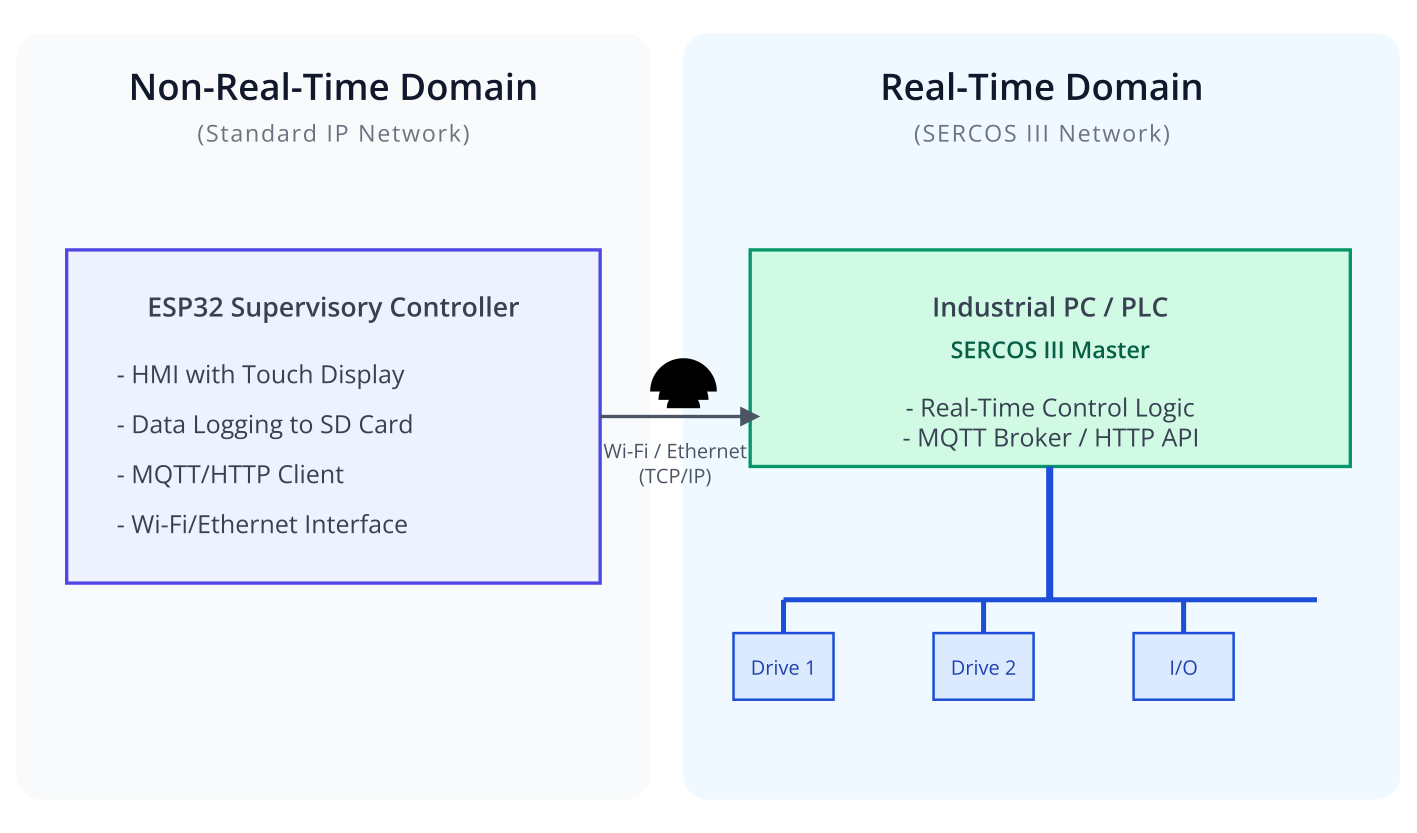
Plausible Roles for ESP32 in a SERCOS III Environment:
Instead of direct participation in the real-time SERCOS III network, an ESP32 could be used in ancillary or supervisory roles:
- Interfacing with a SERCOS III Master Controller:
- The ESP32 could communicate with a dedicated SERCOS III master (e.g., an industrial PC or PLC) using standard protocols like:
- MQTT: For sending commands or receiving status updates.
- HTTP REST API: For configuration or data retrieval.
- OPC UA: If the master supports an OPC UA server.
- Modbus TCP: If the master provides a Modbus TCP interface.
- In this scenario, the ESP32 acts as a user interface, a data aggregator, or a bridge to other networks (e.g., Wi-Fi, LoRaWAN), while the dedicated master handles all SERCOS III real-time communication.
- The ESP32 could communicate with a dedicated SERCOS III master (e.g., an industrial PC or PLC) using standard protocols like:
- Gateway Device Component:
- An ESP32 could be part of a custom gateway device. The gateway itself would have a dedicated SERCOS III interface (FPGA/ASIC based) on one side and other network interfaces (e.g., Ethernet/IP, PROFINET, Wi-Fi) managed by the ESP32 on the other side. The ESP32 would handle data mapping and protocol translation for non-real-time data.
- Simple HMI or Diagnostic Tool:
- An ESP32 with a display could provide a local HMI for a machine controlled by SERCOS III, getting data from the main SERCOS master via a standard network link.
- It could also be used to display diagnostic information gathered from the SERCOS III network through the master or a gateway.
Practical Examples (Conceptual)
The following examples are conceptual and focus on the ESP32 interacting with a higher-level system component (like a PLC acting as a SERCOS Master) that manages the SERCOS III network. They do not involve direct SERCOS III telegram manipulation by the ESP32.
Assumptions:
- A PLC or Industrial PC is acting as the SERCOS III Master.
- This SERCOS Master exposes an API (e.g., HTTP REST or MQTT) for external systems to send commands or request data.
- The ESP32 has Ethernet or Wi-Fi connectivity.
Code Snippet 1: Sending a “Start Cycle” Command via HTTP (Conceptual)
The ESP32 sends an HTTP POST request to the SERCOS Master PLC to trigger a machine cycle.
#include <stdio.h>
#include "freertos/FreeRTOS.h"
#include "freertos/task.h"
#include "esp_wifi.h"
#include "esp_event.h"
#include "nvs_flash.h"
#include "esp_http_client.h"
#include "esp_log.h"
#include "wifi_connect.h" // Assume a utility for Wi-Fi connection

static const char *TAG = "SERCOS_SUPERVISOR";

// Assume wifi_connect_sta() is defined elsewhere and connects to Wi-Fi
// extern void wifi_connect_sta(const char* ssid, const char* pass);


esp_err_t http_event_handler(esp_http_client_event_t *evt) {
    switch(evt->event_id) {
        case HTTP_EVENT_ERROR:
            ESP_LOGD(TAG, "HTTP_EVENT_ERROR");
            break;
        case HTTP_EVENT_ON_CONNECTED:
            ESP_LOGD(TAG, "HTTP_EVENT_ON_CONNECTED");
            break;
        case HTTP_EVENT_HEADER_SENT:
            ESP_LOGD(TAG, "HTTP_EVENT_HEADER_SENT");
            break;
        case HTTP_EVENT_ON_HEADER:
            ESP_LOGD(TAG, "HTTP_EVENT_ON_HEADER, key=%s, value=%s", evt->header_key, evt->header_value);
            break;
        case HTTP_EVENT_ON_DATA:
            ESP_LOGD(TAG, "HTTP_EVENT_ON_DATA, len=%d", evt->data_len);
            if (!esp_http_client_is_chunked_response(evt->client)) {
                // Log data if needed
            }
            break;
        case HTTP_EVENT_ON_FINISH:
            ESP_LOGD(TAG, "HTTP_EVENT_ON_FINISH");
            break;
        case HTTP_EVENT_DISCONNECTED:
            ESP_LOGD(TAG, "HTTP_EVENT_DISCONNECTED");
            break;
        case HTTP_EVENT_REDIRECT:
             ESP_LOGD(TAG, "HTTP_EVENT_REDIRECT");
            break;
    }
    return ESP_OK;
}

void send_start_cycle_command_task(void *pvParameters) {
    // Wait for Wi-Fi connection
    // This would typically be signaled by an event group from wifi_connect.c
    vTaskDelay(pdMS_TO_TICKS(5000)); // Simple delay for example

    ESP_LOGI(TAG, "Sending 'Start Cycle' command to SERCOS Master PLC...");

    char post_data[64];
    snprintf(post_data, sizeof(post_data), "{\"command\":\"start_machine_cycle\"}");

    esp_http_client_config_t config = {
        .url = "http://192.168.1.100/api/machine/control", // Replace with actual PLC IP/endpoint
        .event_handler = http_event_handler,
        .method = HTTP_METHOD_POST,
    };
    esp_http_client_handle_t client = esp_http_client_init(&config);
    esp_http_client_set_header(client, "Content-Type", "application/json");
    esp_http_client_set_post_field(client, post_data, strlen(post_data));

    esp_err_t err = esp_http_client_perform(client);
    if (err == ESP_OK) {
        ESP_LOGI(TAG, "HTTP POST Status = %d, content_length = %lld",
                esp_http_client_get_status_code(client),
                esp_http_client_get_content_length(client));
        // You might get a response body confirming the command
    } else {
        ESP_LOGE(TAG, "HTTP POST request failed: %s", esp_err_to_name(err));
    }

    esp_http_client_cleanup(client);
    vTaskDelete(NULL);
}

void app_main(void) {
    // Initialize NVS
    esp_err_t ret = nvs_flash_init();
    if (ret == ESP_ERR_NVS_NO_FREE_PAGES || ret == ESP_ERR_NVS_NEW_VERSION_FOUND) {
      ESP_ERROR_CHECK(nvs_flash_erase());
      ret = nvs_flash_init();
    }
    ESP_ERROR_CHECK(ret);

    // Initialize Wi-Fi (assuming wifi_connect.c handles this)
    // ESP_ERROR_CHECK(esp_netif_init());
    // ESP_ERROR_CHECK(esp_event_loop_create_default());
    // wifi_connect_sta("your_ssid", "your_password"); // Replace with your credentials

    ESP_LOGI(TAG, "ESP32 SERCOS Supervisor Application Started.");
    // For testing, directly call the task. In a real app, trigger it based on an event (e.g., button press).
    // xTaskCreate(send_start_cycle_command_task, "http_cmd_task", 8192, NULL, 5, NULL);
}
Explanation:
- This code uses the ESP-IDF
esp_http_clientcomponent to send a JSON command to an HTTP endpoint presumably exposed by the SERCOS Master PLC. - The PLC would receive this command and then translate it into the appropriate SERCOS III actions (e.g., commanding drives to start a motion sequence).
- The ESP32 is not involved in any direct SERCOS III communication. It’s using standard IT protocols.
wifi_connect.hand its implementation are assumed to handle the Wi-Fi connection.
Build and Run (Conceptual)
- Setup:
- Ensure you have a Wi-Fi network.
- Have a target HTTP server (simulating the PLC’s API) that can receive the POST request.
- Build:
idf.py build - Flash & Monitor:
idf.py -p (PORT) flash monitor - Observe:
- Wi-Fi connection logs.
- Logs from the ESP32 indicating the HTTP POST request being sent.
- Check the server logs to see if the request was received.
Variant Notes
For the supervisory roles described (communicating with a SERCOS master via standard Ethernet/Wi-Fi), the choice of ESP32 variant primarily depends on the required connectivity and other application needs:
- ESP32, ESP32-S3: These variants with built-in Wi-Fi and Bluetooth are well-suited. The original ESP32 also has an Ethernet MAC (requires an external PHY), and ESP32-S3 can support Ethernet via SPI-Ethernet bridges. Dual cores can help manage Wi-Fi/TCP/IP stack separately from application logic.
- ESP32-S2: Single-core with Wi-Fi. Suitable for simpler supervisory tasks.
- ESP32-C3, ESP32-C6, ESP32-H2: These RISC-V variants also have Wi-Fi and/or Bluetooth. ESP32-C6 and H2 also support 802.15.4 (Thread/Zigbee). Their processing power is generally sufficient for handling HTTP clients, MQTT, etc.
Key Considerations for All Variants in this Context:
- Network Interface: The primary requirement is a stable network interface (Wi-Fi or Ethernet) to communicate with the SERCOS master system.
- Processing Power for Application Logic: The ESP32 needs to run its own application (e.g., HMI logic, data processing, decision-making) in addition to network communication. Modern ESP32s are generally capable.
- Memory (Flash/RAM): Sufficient memory is needed for the application, network stacks (TCP/IP, MQTT/HTTP libraries), and any data buffering.
- No Direct SERCOS III Capability: It’s crucial to reiterate that none of these variants can directly implement SERCOS III real-time communication. Any interaction with SERCOS III will be indirect.
Common Mistakes & Troubleshooting Tips
| Issue / Mistake | Common Symptom(s) | Troubleshooting / Solution |
|---|---|---|
| Network Won’t Start / Slaves Not Found | Master controller reports missing slaves. Link/Status LEDs on slave devices are red or off. Communication phase doesn’t advance. |
1. Check Physical Layer: Verify all Ethernet cables are securely plugged in. Check for damaged cables or connectors. 2. Power Cycle Slaves: Ensure all slave devices have power. A simple power cycle can resolve initialization issues. 3. Verify Topology: In a line topology, ensure devices are daisy-chained correctly (Port 1 to Port 2). In a ring, ensure the last device connects back to the master. 4. Check Master Config: Confirm the project configuration in the master matches the physical network (correct number of slaves, correct addresses). |
| Communication Errors / Lost Telegrams | Machine motion is jerky or stops intermittently. The master logs errors like “MDT/AT not received” or CRC errors. |
1. Check for EMI: Ensure SERCOS cables are properly shielded and grounded. Route them away from high-power cables (motor leads). 2. Cable Quality: Use high-quality industrial Ethernet cables rated for the application. 3. Cycle Time: The configured cycle time might be too short for the number of devices. Try increasing the cycle time to see if stability improves. 4. Faulty Device: A single faulty slave can disrupt the entire network. Try disconnecting slaves one by one to isolate the problematic device. |
| IP Communication (NRT Channel) Fails | Real-time motion control works perfectly, but you cannot ping a slave, access its web server, or use other TCP/IP-based services. |
1. Enable NRT Channel: Verify that the non-real-time (NRT) or Unified Communication Channel (UCC) is enabled and allocated bandwidth in the master’s configuration. 2. Check IP Addresses: Confirm that the slave devices have valid, unique IP addresses configured. Check the IP address of your engineering PC. 3. Firewall Issues: The firewall on your computer or an intermediate network device might be blocking the connection. |
| Ring Redundancy Doesn’t Work | Disconnecting a single cable in a physical ring topology brings down the entire network segment instead of allowing it to continue operating. |
1. Enable Redundancy in Master: Ring redundancy is a specific feature that must be enabled in the SERCOS master’s project settings. 2. Verify Physical Ring: Double-check that the last device’s output port is physically cabled back to the master’s second port to complete the ring. 3. Check Device Support: While most SERCOS III devices support it, confirm all slaves in the ring are capable of redundancy operation. |
Exercises
- Research SERCOS III Master Solutions:
- Identify two examples of commercial SERCOS III Master controllers (e.g., from Bosch Rexroth, Schneider Electric, Siemens, Beckhoff, etc.).
- Briefly describe their typical hardware platform (e.g., Industrial PC, PLC module) and how they might expose data/control interfaces to other systems (e.g., OPC UA, Ethernet/IP, custom APIs).
- Conceptual Design: ESP32 as a SERCOS Diagnostic Display:
- Imagine a machine uses SERCOS III for its drives. The SERCOS III Master PLC makes diagnostic information (e.g., drive temperatures, error codes) available via an MQTT broker.
- Outline the software components and logic on an ESP32 (with Wi-Fi and a small display) that would subscribe to relevant MQTT topics and display this diagnostic information. What ESP-IDF components would be primarily used?
- SERCOS III vs. EtherCAT vs. PROFINET IRT:
- Create a brief comparison (a few bullet points for each) of SERCOS III, EtherCAT, and PROFINET IRT focusing on:
- Primary application areas.
- Typical cycle times.
- Basic principle of real-time data exchange.
- Create a brief comparison (a few bullet points for each) of SERCOS III, EtherCAT, and PROFINET IRT focusing on:
Summary
- SERCOS III is a high-performance, Ethernet-based real-time communication protocol primarily for demanding motion control applications.
- It ensures determinism and precise synchronization through short cycle times and specialized communication mechanisms (MDT/AT telegrams).
- Key features include line/ring topology, integrated 2-port switches in devices, and a non-real-time service channel for IP traffic.
- Direct implementation of SERCOS III master or slave stacks on an ESP32 is not feasible due to its stringent real-time hardware and software requirements.
- An ESP32 can play a supervisory or ancillary role by communicating with a dedicated SERCOS III Master (PLC/IPC) or gateway using standard network protocols (HTTP, MQTT, etc.).
- ESP32 variants with Ethernet or Wi-Fi can be used for these higher-level interactions, focusing on tasks like HMI, configuration, data logging, or bridging to other networks.
- Understanding the boundary between the ESP32’s non-real-time role and the SERCOS III system’s real-time domain is crucial for successful integration.
Further Reading
- SERCOS International e.V.: https://www.sercos.org/ (Official organization for SERCOS standards, news, and resources).
- IEC 61491: The international standard for SERCOS.
- White Papers and Application Notes: From SERCOS International and vendors of SERCOS III components (e.g., Bosch Rexroth, Yaskawa, Schneider Electric).
- ESP-IDF API Reference – HTTP Client: https://docs.espressif.com/projects/esp-idf/en/v5.4/esp32/api-reference/protocols/esp_http_client.html
- ESP-IDF API Reference – MQTT: https://docs.espressif.com/projects/esp-idf/en/v5.4/esp32/api-reference/protocols/mqtt.html
