
Chapter 161: SDM Configuration and Usage
Chapter Objectives
By the end of this chapter, you will be able to:
- Master advanced configuration parameters for the SDM peripheral, including clock sources and sample rates.
- Understand how to calculate and set the prescaler for the SDM clock.
- Implement SDM configurations to generate precise and stable DC voltage levels.
- Explore how SDM-generated analog-like outputs can be utilized in sensor-based systems, for example, by providing reference voltages or controlling actuators.
- Configure and use multiple SDM channels simultaneously.
- Design appropriate external filters for various SDM applications.
- Identify and troubleshoot common issues related to SDM configuration and output signal quality.
Introduction
In Chapter 160, we introduced the Sigma-Delta Modulation (SDM) peripheral, its underlying theory, and a basic example of generating a variable DC output. We learned that SDM provides a clever way to produce analog-like signals using a high-frequency 1-bit digital stream, which, when filtered, can approximate a desired analog voltage.
This chapter takes a deeper dive into the practical aspects of configuring and utilizing the SDM peripheral on compatible ESP32 variants. We will explore the nuances of clock selection, sample rate settings, and prescaler calculations, all ofwhich are critical for tailoring the SDM output to specific application needs. A significant focus will be on how these digitally generated analog-like signals can play a role in systems involving sensors—not by directly reading sensors, but by providing stable reference voltages that some sensors require, or by driving actuators based on sensor-derived data processed by the ESP32. We will also cover multi-channel operation and advanced filtering considerations to help you harness the full potential of this versatile peripheral.
Theory: Advanced Configuration Details
Effectively using the SDM peripheral requires a good understanding of its configuration parameters. These settings determine the characteristics of the output pulse stream and, consequently, the quality of the analog signal produced after external filtering.
1. Clock Sources (sdm_clock_source_t)
The SDM peripheral needs a clock source to drive its internal modulator. The choice of clock source can impact the maximum achievable sample rate, stability, and power consumption. ESP-IDF provides several options through the sdm_config_t::clk_src field:
Clock Source (clk_src) |
Supported On | Typical Frequency | Pros | Cons |
|---|---|---|---|---|
SDM_CLK_SRC_DEFAULT |
ESP32, S2, S3 | ~80 MHz (APB_CLK) | High frequency allows high sample rates. Simple to use. | Frequency may depend on other system settings (e.g., CPU speed). |
SDM_CLK_SRC_XTAL |
ESP32-S2, S3 | 40 MHz | Highly stable and precise. Good for low-jitter applications. | Lower max frequency than APB_CLK. Not on original ESP32. |
SDM_CLK_SRC_RTC_FAST |
ESP32-S3 | ~8-20 MHz | Can be used in some low-power scenarios where APB clock is gated. | Lower frequency, less stable than XTAL. Limits max sample rate. |
Implications of Clock Choice:
- Frequency & Stability: APB_CLK is high frequency but its exact value can depend on CPU frequency settings. XTAL is highly stable. RTC_FAST is lower frequency and might have more jitter than XTAL.
- Power Consumption: Using a faster clock source (like APB_CLK at full speed) will generally consume more power.
- Maximum Sample Rate: A higher frequency clock source allows for a higher
sample_rate_hzfor the SDM modulator, which can improve noise shaping performance.
2. Sample Rate (sample_rate_hz)
The sdm_config_t::sample_rate_hz field specifies the target operating frequency of the SDM modulator itself. This is the rate at which the 1-bit quantizer makes decisions and outputs bits.
- Impact on Output:
- Noise Shaping: Higher sample rates generally allow the noise shaping mechanism to be more effective, pushing quantization noise further into higher frequencies. This makes it easier for the external low-pass filter to remove the noise.
- Resolution & Ripple: A higher sample rate, when combined with an appropriate filter, can lead to a smoother output with less ripple and effectively higher resolution.
- Response Time: A higher sample rate allows for faster changes in the output density to be reflected in the filtered analog signal, assuming the filter’s cutoff frequency is also appropriately high.
3. Prescaler Calculation
The SDM hardware uses an internal prescaler to derive its operating clock (sample_rate_hz) from the selected clk_src. The relationship is:
prescaler = clk_src_frequency / sample_rate_hz
The ESP-IDF SDM driver automatically calculates the required integer prescaler based on the clk_src you choose (it knows the frequency of SDM_CLK_SRC_DEFAULT, SDM_CLK_SRC_XTAL, etc.) and the sample_rate_hz you request.
- Valid Prescaler Range: The hardware prescaler has limits. For instance, on ESP32, the prescaler value (often referred to as
SDM_PRESCALEor similar in TRM, though abstracted by driver) might range from 1 to 255 or 2 (even values) to 256. The driver will attempt to find the closest valid prescaler.- If the calculated prescaler is outside the valid hardware range (e.g., less than 1, meaning
sample_rate_hzis higher thanclk_src_frequency), channel allocation will fail. - You typically don’t set the prescaler directly in ESP-IDF v5.x; you set the
sample_rate_hz, and the driver handles it. However, understanding this relationship is crucial for choosing a feasiblesample_rate_hz.
clk_srcis APB_CLK at 80 MHz:- To get
sample_rate_hz = 1 MHz, prescaler = 80 MHz / 1 MHz = 80. (Valid) - To get
sample_rate_hz = 8 MHz, prescaler = 80 MHz / 8 MHz = 10. (Valid) - To get
sample_rate_hz = 80 MHz, prescaler = 80 MHz / 80 MHz = 1. (Valid, minimum prescaler) - Attempting
sample_rate_hz = 100 MHzwould be invalid as prescaler < 1.
- If the calculated prescaler is outside the valid hardware range (e.g., less than 1, meaning
graph TD
    subgraph Driver Logic
        A["Start: sdm_new_channel()"]:::primary
        B["Read User's sdm_config_t<br>(gpio_num, clk_src, sample_rate_hz)"]:::process
        C{Get Frequency of<br>Chosen 'clk_src'}:::decision
        D[Calculate Prescaler:<br>prescaler = clk_src_freq / sample_rate_hz]:::process
        E{"Is 'prescaler' within<br>valid hardware range?<br>(e.g., 1 to 256)"}:::decision
        F[Configure Hardware<br>with Calculated Prescaler]:::process
        G["Return Success (ESP_OK) and<br>Channel Handle"]:::success
        H["Return Error<br>(ESP_ERR_INVALID_ARG)"]:::check
    end

    A --> B
    B --> C
    C --> D
    D --> E
    E --"Yes"--> F
    E --"No"--> H
    F --> G

    classDef primary fill:#EDE9FE,stroke:#5B21B6,stroke-width:2px,color:#5B21B6;
    classDef success fill:#D1FAE5,stroke:#059669,stroke-width:2px,color:#065F46;
    classDef decision fill:#FEF3C7,stroke:#D97706,stroke-width:1px,color:#92400E;
    classDef process fill:#DBEAFE,stroke:#2563EB,stroke-width:1px,color:#1E40AF;
    classDef check fill:#FEE2E2,stroke:#DC2626,stroke-width:1px,color:#991B1B;
4. Density Value and Output Voltage
As covered in Chapter 160, the sdm_channel_set_pulse_density(channel, density) function is used to control the output. The density parameter is an int, but effectively treated as an int8_t by the driver, ranging from -128 to 127.
- Effective Duty Cycle: This density value translates to an effective duty cycle of the pulse stream:Effective Duty Cycle = (density + 128) / 256.0
density = -128=> Effective Duty Cycle = 0 / 256.0 = 0.0 (0%)density = 0=> Effective Duty Cycle = 128 / 256.0 = 0.5 (50%)density = 127=> Effective Duty Cycle = 255 / 256.0 = ~0.996 (approx. 100%)
| Target | Density Value (int8_t) |
Effective Duty Cycle | Approx. Output Voltage (at 3.3V) |
|---|---|---|---|
| Minimum Output | -128 |
0.0% | ~0.00 V |
| ~25% Output | -64 |
25.0% | ~0.83 V |
| Target 1.25V (from example) | -31 |
37.9% | ~1.25 V |
| 50% Output | 0 |
50.0% | ~1.65 V |
| ~75% Output | 64 |
75.0% | ~2.48 V |
| Maximum Output | 127 |
99.6% | ~3.29 V |
- Approximate Output Voltage (after filtering):V_out_approx = VDD * Effective Duty CycleWhere VDD is the supply voltage of the ESP32 (typically 3.3V).For example, to get approximately 1.25V from a 3.3V supply:1.25V = 3.3V * (density + 128) / 256.0(density + 128) = (1.25V / 3.3V) * 256.0(density + 128) \approx 0.3788 * 256.0 \approx 97density \approx 97 – 128 = -31So, setting density = -31 should yield approximately 1.25V.
5. Multi-Channel Operation
ESP32 variants with SDM support multiple channels (e.g., 8 on ESP32, 4 on ESP32-S2/S3). Each channel can be configured and controlled independently:
- Each channel is associated with a specific GPIO pin.
- Each channel can have its own
sample_rate_hzif desired (though often they share the same clock source characteristics). - You would call
sdm_new_channel()for each channel you intend to use, obtaining a uniquesdm_channel_handle_tfor each.
This allows for generating multiple independent analog-like signals simultaneously.

6. Filtering Considerations for Precision Applications
The external low-pass filter is paramount for achieving a clean and stable analog output.
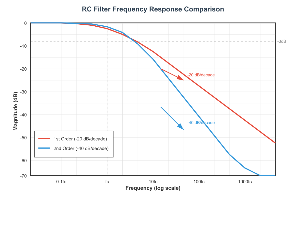
- Simple RC Filter: The most common is a first-order RC filter.
- Cutoff Frequency: fc=1/(2πRC)
- The cutoff frequency fc should be significantly lower than the SDM
sample_rate_hzto effectively attenuate the high-frequency components of the pulse stream and the shaped noise. A common rule of thumb is fc<sampleratehz/10 or even lower for smoother output. - Trade-off:
- Lower fc (larger R or C): Smoother DC output, less ripple, but slower response to changes in
density. - Higher fc (smaller R or C): Faster response, but more ripple.
- Lower fc (larger R or C): Smoother DC output, less ripple, but slower response to changes in
- Cutoff Frequency: fc=1/(2πRC)
- Higher-Order Filters: For applications demanding very low ripple (e.g., precision voltage references), a second-order (or higher) RC or active filter (using op-amps) might be necessary. These can provide a steeper roll-off, attenuating unwanted frequencies more effectively.
- Component Selection: Use stable, low-tolerance resistors and capacitors (e.g., film capacitors for better stability over temperature than some ceramics for the C in RC filters, especially if precision is key).
Practical Examples
Let’s put this theory into practice with more detailed examples.
Prerequisites:
- ESP-IDF v5.x, VS Code with Espressif IDF Extension.
- An ESP32, ESP32-S2, or ESP32-S3 board.
- LEDs, resistors, capacitors for filtering.
- A multimeter or oscilloscope for verification.
Example 1: Generating a Precise 1.25V Reference Voltage
This example demonstrates configuring SDM to output a stable DC voltage, suitable as a Vref for an analog sensor or comparator.
Hardware:
- SDM output GPIO (e.g., GPIO4) connected to an RC filter: R = 10kΩ, C = 1µF.
- fc=1/(2π∗10000∗0.000001)≈1/(0.0628)≈15.9Hz. This is a low cutoff for a stable DC.
- Multimeter to measure the voltage across the capacitor.
File: main/sdm_ref_voltage_main.c
#include <stdio.h>
#include "freertos/FreeRTOS.h"
#include "freertos/task.h"
#include "driver/sdm.h"
#include "esp_log.h"
#include "soc/soc_caps.h" // For SOC_SDM_SUPPORTED

static const char *TAG = "SDM_REF_VOLTAGE";

#define SDM_OUTPUT_GPIO GPIO_NUM_4 // Choose an available GPIO
#define TARGET_VOLTAGE_MV 1250     // Target 1.25V
#define VDD_MV 3300                // Assuming 3.3V VDD

#if SOC_SDM_SUPPORTED
void app_main(void)
{
    ESP_LOGI(TAG, "Initializing SDM channel for %d mV reference voltage on GPIO %d", TARGET_VOLTAGE_MV, SDM_OUTPUT_GPIO);

    sdm_channel_handle_t sdm_chan = NULL;
    sdm_config_t config = {
        .gpio_num = SDM_OUTPUT_GPIO,
        .clk_src = SDM_CLK_SRC_DEFAULT, // Typically APB_CLK
        .sample_rate_hz = 4 * 1000 * 1000, // 4 MHz sample rate. Higher can be better.
                                          // Max depends on clk_src and prescaler limits.
                                          // e.g. if APB is 80MHz, prescaler = 80/4 = 20 (valid)
    };

    ESP_LOGI(TAG, "Attempting to allocate SDM channel...");
    esp_err_t ret = sdm_new_channel(&config, &sdm_chan);
    if (ret != ESP_OK) {
        ESP_LOGE(TAG, "Failed to allocate SDM channel: %s", esp_err_to_name(ret));
        return;
    }
    ESP_LOGI(TAG, "SDM channel allocated successfully.");

    ret = sdm_channel_enable(sdm_chan);
    if (ret != ESP_OK) {
        ESP_LOGE(TAG, "Failed to enable SDM channel: %s", esp_err_to_name(ret));
        sdm_del_channel(sdm_chan);
        return;
    }
    ESP_LOGI(TAG, "SDM channel enabled.");

    // Calculate density for target voltage
    // Effective Duty Cycle = TARGET_VOLTAGE_MV / VDD_MV
    // (density + 128) / 256.0 = TARGET_VOLTAGE_MV / VDD_MV
    // density = ( (TARGET_VOLTAGE_MV / VDD_MV) * 256.0 ) - 128
    float effective_duty_target = (float)TARGET_VOLTAGE_MV / VDD_MV;
    int calculated_density = (int)(effective_duty_target * 256.0f - 128.0f);

    // Clamp density to int8_t range
    int8_t density_to_set;
    if (calculated_density < -128) {
        density_to_set = -128;
    } else if (calculated_density > 127) {
        density_to_set = 127;
    } else {
        density_to_set = (int8_t)calculated_density;
    }

    ESP_LOGI(TAG, "Calculated density for %.2fV: %d (target effective duty: %.3f)",
             TARGET_VOLTAGE_MV / 1000.0f, density_to_set, effective_duty_target);

    ret = sdm_channel_set_pulse_density(sdm_chan, density_to_set);
    if (ret != ESP_OK) {
        ESP_LOGE(TAG, "Failed to set SDM density: %s", esp_err_to_name(ret));
    } else {
        ESP_LOGI(TAG, "SDM density set to %d. Measure voltage on GPIO %d (after RC filter).",
                 density_to_set, SDM_OUTPUT_GPIO);
    }

    // Keep the task alive or the SDM output might stop if app_main exits on some FreeRTOS configs.
    // For a fixed voltage, no loop is needed here once set.
    while(1) {
        vTaskDelay(pdMS_TO_TICKS(1000));
    }

    // Proper cleanup (not reached in this example's while(1))
    // sdm_channel_disable(sdm_chan);
    // sdm_del_channel(sdm_chan);
}
#else
void app_main(void)
{
    ESP_LOGE(TAG, "SDM peripheral is not supported on this ESP32 variant.");
}
#endif // SOC_SDM_SUPPORTED
Build, Flash, Observe:
- Save the code.
- Build:
idf.py build - Flash:
idf.py -p (PORT) flash - Monitor:
idf.py -p (PORT) monitor - Measure the voltage across the capacitor with a multimeter. It should be close to 1.25V. Small deviations can occur due to VDD fluctuations, resistor/capacitor tolerances, and the inherent approximation of SDM.
Sensor Interfacing Context: This stable 1.25V could be used as:
- A reference voltage (Vref) for an external ADC.
- A threshold voltage for an analog comparator.
- A stable bias for certain types of analog sensors.
Example 2: Simulated Actuator Control based on “Sensor” Input
Here, we simulate reading a sensor value (e.g., light level) and use SDM to control an LED’s brightness (acting as a proxy for an actuator like a motor speed controller or a dimmable light).
Hardware:
- SDM output GPIO (e.g., GPIO5) connected to an LED with a current-limiting resistor (e.g., 330Ω).
- Optional: RC filter (e.g., R=1kΩ, C=1µF) if you want to observe the averaged voltage.
File: main/sdm_actuator_control_main.c
#include <stdio.h>
#include "freertos/FreeRTOS.h"
#include "freertos/task.h"
#include "driver/sdm.h"
#include "esp_log.h"
#include "soc/soc_caps.h"

static const char *TAG = "SDM_ACTUATOR_CONTROL";

#define SDM_ACTUATOR_GPIO GPIO_NUM_5 // Choose an available GPIO

#if SOC_SDM_SUPPORTED
// Simulate a sensor reading (e.g., 0 to 1000)
int get_simulated_sensor_value() {
    static int sensor_val = 0;
    sensor_val = (sensor_val + 50) % 1001; // Cycle from 0 to 1000
    return sensor_val;
}

void app_main(void)
{
    ESP_LOGI(TAG, "Initializing SDM for actuator control on GPIO %d", SDM_ACTUATOR_GPIO);

    sdm_channel_handle_t sdm_chan = NULL;
    sdm_config_t config = {
        .gpio_num = SDM_ACTUATOR_GPIO,
        .clk_src = SDM_CLK_SRC_DEFAULT,
        .sample_rate_hz = 1 * 1000 * 1000, // 1 MHz sample rate
    };

    esp_err_t ret = sdm_new_channel(&config, &sdm_chan);
    if (ret != ESP_OK) {
        ESP_LOGE(TAG, "Failed to allocate SDM channel: %s", esp_err_to_name(ret));
        return;
    }

    ret = sdm_channel_enable(sdm_chan);
    if (ret != ESP_OK) {
        ESP_LOGE(TAG, "Failed to enable SDM channel: %s", esp_err_to_name(ret));
        sdm_del_channel(sdm_chan);
        return;
    }
    ESP_LOGI(TAG, "SDM channel enabled for actuator control.");

    while (1) {
        int sensor_value = get_simulated_sensor_value(); // 0 to 1000

        // Map sensor value (0-1000) to density (-128 to 127)
        // ((sensor_value / 1000.0f) * 255.0f) gives 0-255 range
        // Then subtract 128 to get -128 to 127 range
        int8_t density = (int8_t)(((float)sensor_value / 1000.0f) * 255.0f - 128.0f);

        // Ensure density is within valid int8_t range after calculation if sensor_value could be out of 0-1000
        if (density < -128) density = -128;
        if (density > 127) density = 127;


        ret = sdm_channel_set_pulse_density(sdm_chan, density);
        if (ret != ESP_OK) {
            ESP_LOGE(TAG, "Failed to set SDM density: %s", esp_err_to_name(ret));
        } else {
            float effective_duty = (density + 128.0f) / 256.0f;
            ESP_LOGI(TAG, "Simulated Sensor: %4d -> Density: %4d (Effective Duty: %.2f%%)",
                     sensor_value, density, effective_duty * 100.0f);
        }
        vTaskDelay(pdMS_TO_TICKS(200)); // Update actuator every 200ms
    }
}
#else
void app_main(void)
{
    ESP_LOGE(TAG, "SDM peripheral is not supported on this ESP32 variant.");
}
#endif // SOC_SDM_SUPPORTED
Build, Flash, Observe:
- The LED connected to
SDM_ACTUATOR_GPIOshould vary its brightness in response to the simulated sensor value changes. - This demonstrates a basic closed-loop concept: Sensor input (simulated) -> MCU processing (mapping) -> Analog-like output (SDM for LED brightness). In a real system, the LED could be a motor driver input, a proportional valve controller, etc.
Variant Notes
As detailed in Chapter 160 and reiterated here for configuration context:
- ESP32 (Original):
- Supported. 8 SDM channels.
clk_srctypicallySDM_CLK_SRC_DEFAULT(APB_CLK @ 80 MHz).
- ESP32-S2:
- Supported. 4 SDM channels.
clk_srccan beSDM_CLK_SRC_DEFAULT(APB_CLK) orSDM_CLK_SRC_XTAL.
- ESP32-S3:
- Supported. 4 SDM channels.
clk_srccan beSDM_CLK_SRC_DEFAULT(APB_CLK),SDM_CLK_SRC_XTAL, orSDM_CLK_SRC_RTC_FAST.
- ESP32-C3, ESP32-C6, ESP32-H2:
- Not Supported. These variants do not have the dedicated SDM peripheral.
- Alternative: Use the LEDC (PWM) peripheral with a high frequency and an external RC filter to achieve similar analog-like output capabilities. Refer to Chapter 145 for LEDC.
Configuration Differences:
- The primary difference when configuring across supported variants lies in the available
clk_srcoptions and the number of channels. - The core API (
sdm_config_t,sdm_new_channel,sdm_channel_set_pulse_density) remains consistent. - Always check the Technical Reference Manual (TRM) for the specific variant if you need to understand the absolute maximum
sample_rate_hzpossible with a given clock source, as this depends on the hardware prescaler limits.
Common Mistakes & Troubleshooting Tips (Focus on Configuration)
| Mistake / Issue | Symptom(s) | Troubleshooting / Solution |
|---|---|---|
Invalid sample_rate_hz |
sdm_new_channel() fails, returning ESP_ERR_INVALID_ARG. |
Check Prescaler Math: Calculate prescaler = clk_src_freq / sample_rate_hz. The result must be within the hardware limits (e.g., 1-256).Action: Lower the sample_rate_hz or, if possible, choose a faster clk_src.
|
| Inadequate Filtering for Vref | A measured DC reference voltage is noisy, unstable, or has significant ripple when viewed on an oscilloscope. |
1. Lower Filter Cutoff: Your RC filter’s cutoff frequency fc = 1/(2πRC) is too high. Increase R or C (e.g., 10kΩ, 1µF) for a lower fc.2. Consider a 2nd-Order Filter: For very high precision, a simple RC filter may not be enough. Research second-order low-pass filters (e.g., Sallen-Key). |
| Incorrect Density-to-Voltage Calculation | The output voltage is not what was expected based on calculations. For example, setting density to -31 does not produce ~1.25V. |
1. Verify VDD: Did you use the correct VDD in your calculation? Measure your board’s 3.3V rail; it might be 3.25V or 3.35V. 2. Use Floating Point Math: Ensure your calculation in C is done using floating-point numbers to avoid integer truncation, e.g., (int)((target_v / 3.3f) * 256.0f - 128.0f).
|
| Forgetting to Enable Channel | Channel is allocated successfully, but calls to sdm_channel_set_pulse_density() have no effect or return an error. No signal on GPIO. |
Add Enable Call: You must call sdm_channel_enable(channel_handle) after a successful call to sdm_new_channel() and before setting the density.
|
Tip: When debugging SDM output, an oscilloscope is invaluable. It allows you to see the actual pulse stream, the effect of the filter, and measure ripple accurately. A multimeter will only show the average DC voltage.
Exercises
- SDM Output Calibration Routine:
- Write a program where the user can input a target voltage (e.g., between 0.5V and 3.0V) via the UART console.
- The ESP32 should then try to achieve this voltage using SDM.
- If you have another ADC channel available (or an external ADC), try to read back the filtered SDM output and implement a simple feedback loop to fine-tune the
densityvalue to get closer to the target. If no ADC, instruct the user to measure with a multimeter and report if the output is high/low, then allow manual adjustment of density. - Log the final
densityused for several target voltages.
- Simulated Temperature-Controlled Fan/Heater:
- Simulate a temperature sensor by creating a variable that slowly changes (e.g.,
float current_temp = 20.0;). - Implement logic:
- If
current_temp < 15.0(too cold), set SDM output (representing a heater) to 75% duty cycle. - If
15.0 <= current_temp < 25.0(comfortable), set SDM output to 0% duty cycle. - If
current_temp >= 25.0(too hot), set SDM output (representing a fan) to a duty cycle proportional to how muchcurrent_tempexceeds 25.0 (e.g., 25°C = 0% fan, 35°C = 100% fan).
- If
- Use an LED to visualize the “heater” or “fan” output level.
- Simulate a temperature sensor by creating a variable that slowly changes (e.g.,
- Fine-Grained LED Dimming (256 Steps):
- Create a program that smoothly cycles an LED’s brightness through 256 distinct levels.
- Map an input counter (0 to 255) to the SDM
densityrange (-128 to 127). - Observe the smoothness of the transition. Experiment with different
sample_rate_hzand filter values to see their impact on perceived smoothness.
- Two Independent DC Voltage Outputs:
- Configure two SDM channels on two different GPIO pins.
- Set the first channel to output approximately 1.0V.
- Set the second channel to output approximately 2.0V simultaneously.
- Verify the outputs using two LEDs of different brightness (after filtering if needed for stability) or by measuring with a multimeter. This demonstrates multi-channel capability.
Summary
- Advanced SDM configuration involves selecting an appropriate
clk_src(DEFAULT, XTAL, RTC_FAST depending on variant) andsample_rate_hz. - The
sample_rate_hzandclk_srcfrequency determine the hardware prescaler, which must be within valid limits. - The output voltage is controlled by the
densityparameter (-128 to 127), which maps to an effective duty cycle:V_out_approx = VDD * (density + 128) / 256.0. - Proper external low-pass filtering is crucial for converting the SDM pulse stream into a usable analog signal, especially for precision DC levels. Filter design involves trade-offs between ripple and response time.
- SDM outputs can support sensor systems by providing stable reference voltages or by controlling actuators based on MCU-processed sensor data.
- ESP32, ESP32-S2, and ESP32-S3 support multiple SDM channels for independent analog-like outputs. Other variants like ESP32-C3/C6/H2 must use LEDC (PWM) with filtering as an alternative.
- Careful calculation of parameters, robust filtering, and awareness of hardware limitations are key to successful SDM implementation.
Further Reading
- ESP-IDF SDM Driver Documentation:
- Always refer to the latest official ESP-IDF Programming Guide for your ESP-IDF version. Search for “SDM Driver”.
- https://docs.espressif.com/projects/esp-idf/en/v5.4/esp32/api-reference/peripherals/sdm.html
- ESP32 Series Technical Reference Manuals (TRM):
- For detailed hardware information on the Sigma-Delta Modulator, including register maps and block diagrams, consult the TRM for your specific ESP32 variant.
- Espressif Technical Documents: https://www.espressif.com/en/support/documents/technical-documents
- Application Notes on Analog Design and Filtering:
- While not specific to ESP32’s SDM, general application notes from analog device manufacturers (e.g., Texas Instruments, Analog Devices) on topics like DACs, PWM filtering, and active filter design can provide valuable insights into creating high-quality analog signals from digital sources.
