
Chapter 142: RMT for Infrared Communication
Chapter Objectives
After completing this chapter, you will be able to:
- Understand the fundamental principles of infrared (IR) communication.
- Describe the structure and timings of the NEC IR protocol.
- Configure RMT TX channels to generate NEC-compliant IR signals, including carrier modulation.
- Build RMT symbols representing NEC address and command codes.
- Configure RMT RX channels to receive and demodulate IR signals.
- Parse received RMT symbols to decode NEC address and command codes.
- Implement basic IR transmitter and receiver applications using ESP-IDF v5.x.
- Understand how to handle NEC repeat codes.
- Be aware of common issues and troubleshooting techniques for IR communication with ESP32.
Introduction
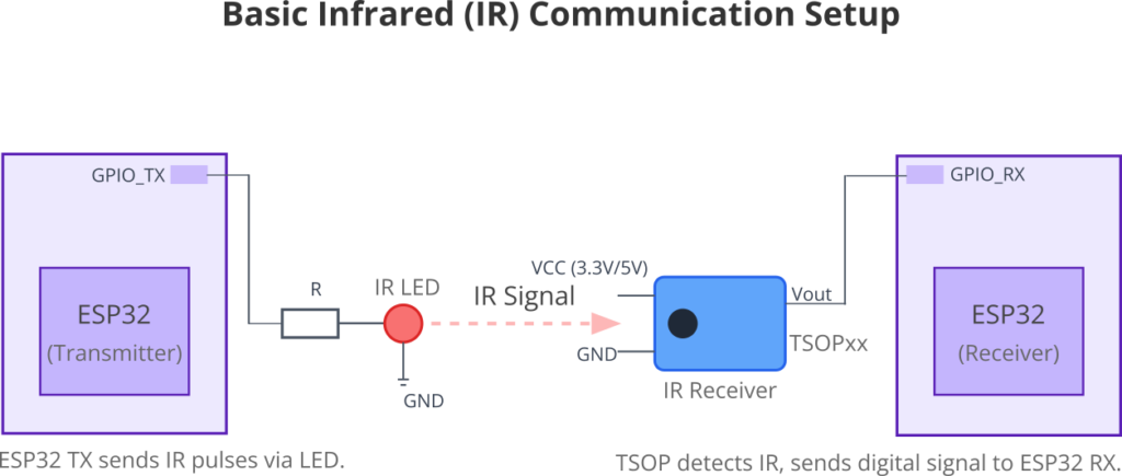
Infrared communication is a ubiquitous technology, widely used in consumer electronics for remote controls (TVs, air conditioners, audio systems), short-range data transfer, and proximity sensing. Its simplicity, low cost, and immunity to radio frequency interference make it an attractive option for many applications.
In the previous chapter, we explored the ESP32’s RMT (Remote Control) peripheral as a versatile tool for generating and receiving generic pulse-based signals. Now, we will apply that knowledge specifically to the realm of infrared communication. The RMT module is exceptionally well-suited for handling the precise timings and carrier modulation required by most IR protocols.
This chapter will focus on implementing IR communication, primarily using the popular NEC protocol as a case study. We will learn how to use the RMT peripheral to both transmit IR commands (acting as a remote control) and receive IR commands (acting as a device being controlled).
Theory
Basics of Infrared Communication
Infrared (IR) light is electromagnetic radiation with wavelengths longer than visible light but shorter than microwaves. For communication, specific IR wavelengths are used, typically around 850nm to 950nm.
- IR Emitters (LEDs): An IR LED (Light Emitting Diode) is used to transmit IR signals. When current flows through it, it emits IR light.
- IR Receivers/Demodulators: An IR receiver module (e.g., TSOPxx series like TSOP38238, TSOP1738) is used to detect IR signals. These modules are not just photodiodes; they typically include:
- A photodiode sensitive to IR light.
- An amplifier to strengthen the detected signal.
- A band-pass filter tuned to a specific carrier frequency (e.g., 38kHz).
- A demodulator to extract the original digital signal from the carrier.
- An output stage that provides a clean digital signal (e.g., active low when IR is detected).
Carrier Frequency and Modulation
Raw IR signals are susceptible to interference from ambient IR sources like sunlight or incandescent lighting. To overcome this, IR communication typically uses Amplitude Shift Keying (ASK) modulation. The digital data (on/off pulses) is modulated onto a higher-frequency carrier wave, usually between 30kHz and 60kHz (38kHz is very common for NEC).
- Modulation: When a ‘1’ (or a mark period) needs to be sent, the IR LED is pulsed on and off at the carrier frequency. When a ‘0’ (or a space period) is sent, the IR LED is kept off.
- Demodulation: The IR receiver module is tuned to this specific carrier frequency. It filters out other frequencies and detects the presence or absence of the carrier, thus demodulating the signal back into the original digital pulses.

The RMT peripheral’s TX channels have built-in support for generating carrier waves, making IR signal generation straightforward.
Overview of Common IR Protocols
Several standard IR protocols exist, each with its own timing, data format, and features. Some common ones include:
| Protocol | Developer/Origin | Typical Carrier Freq. | Bit Encoding | Key Features/Notes |
|---|---|---|---|---|
| NEC | NEC Corporation | 38 kHz | Pulse Distance Encoding (fixed pulse mark, variable space) | Address (8-bit + inverse), Command (8-bit + inverse), LSB first, repeat codes. Widely used. |
| RC-5 | Philips | 36 kHz | Manchester (bi-phase) | Start bits, toggle bit, 5-bit address, 6-bit command. Constant bit time. |
| RC-6 | Philips | 36 kHz | Manchester variant (bi-phase) | More complex than RC-5, longer header, more data bits (e.g., 8-bit command), toggle bit. |
| Sony SIRC | Sony | 40 kHz | Pulse Width Encoding (fixed pulse space, variable mark) | Different versions (12-bit, 15-bit, 20-bit) for address and command. LSB first. |
| Others | Various (e.g., JVC, Panasonic, Sharp) | Many manufacturers have proprietary or less common protocols with unique timings and structures. | ||
While the principles are similar, the exact pulse durations for leaders, bits, and repeats vary significantly. The RMT module’s flexibility allows it to implement many of these.
The NEC IR Protocol
The NEC protocol is a popular choice due to its simplicity and reliability. Let’s break down its structure:
1. Carrier Frequency:
Typically 38kHz. The duty cycle of the carrier is often 1/3 or 1/4 (e.g., for a 38kHz carrier, the pulse width is ~8.77µs for a 1/3 duty cycle).
2. Timings:
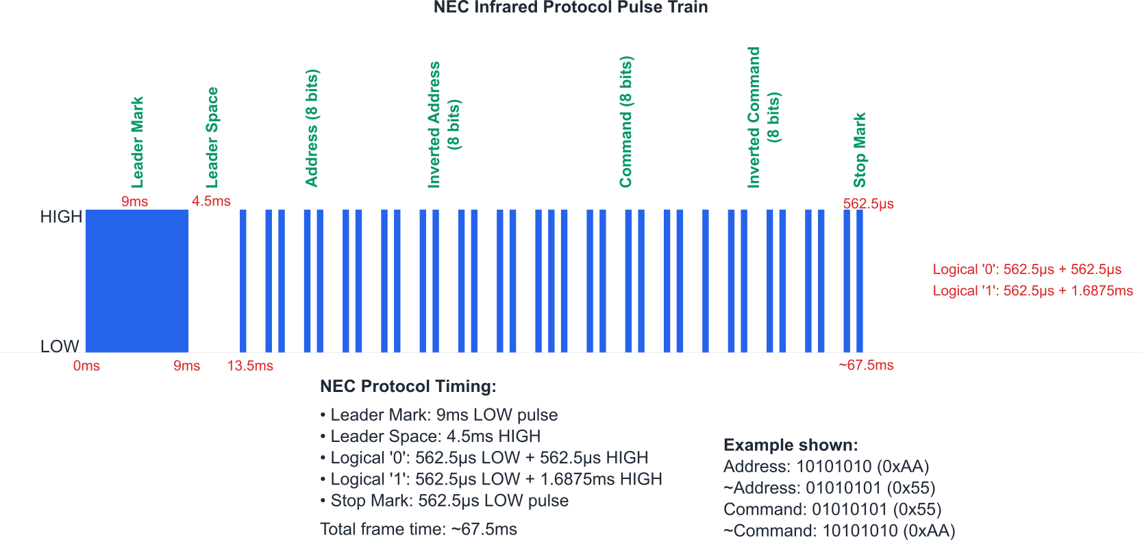
Based on a fundamental time unit ‘T’, which is typically 562.5µs.
- Leader Code:
- 9ms (16T) mark (carrier ON).
- 4.5ms (8T) space (carrier OFF).
- 9ms (16T) mark (carrier ON).
- Data Bits (Logical ‘0’ and ‘1’):
- Logical ‘0’: 562.5µs (1T) mark + 562.5µs (1T) space. Total 1.125ms.
- Logical ‘1’: 562.5µs (1T) mark + 1.6875ms (3T) space. Total 2.25ms.
- Logical ‘0’: 562.5µs (1T) mark + 562.5µs (1T) space. Total 1.125ms.
- Stop Bit: A final 562.5µs (1T) mark pulse after all data bits to signify the end of the message.
- Message Structure:
Leader Code -> 8-bit Address -> 8-bit Inverted Address -> 8-bit Command -> 8-bit Inverted Command -> Stop Bit.
graph LR
    subgraph "NEC IR Message Frame Structure (LSB First for Address/Command Data)"
        direction LR
        A
        Start((Start Frame)) --> LDR[Leader Code <br> 9ms Mark + 4.5ms Space];
        style LDR fill:#EDE9FE,stroke:#5B21B6,stroke-width:2px,color:#5B21B6

        LDR --> ADDR[8-bit Address];
        style ADDR fill:#DBEAFE,stroke:#2563EB,stroke-width:1px,color:#1E40AF

        ADDR --> INV_ADDR["8-bit Inverted Address <br> (Error Check)"];
        style INV_ADDR fill:#DBEAFE,stroke:#2563EB,stroke-width:1px,color:#1E40AF

        INV_ADDR --> CMD[8-bit Command];
        style CMD fill:#DBEAFE,stroke:#2563EB,stroke-width:1px,color:#1E40AF

        CMD --> INV_CMD["8-bit Inverted Command <br> (Error Check)"];
        style INV_CMD fill:#DBEAFE,stroke:#2563EB,stroke-width:1px,color:#1E40AF

        INV_CMD --> STOP_BIT[Stop Bit <br> 0.56ms Mark];
        style STOP_BIT fill:#FEF3C7,stroke:#D97706,stroke-width:1px,color:#92400E

        STOP_BIT --> EndFrame((End Frame));
        style EndFrame fill:#D1FAE5,stroke:#059669,stroke-width:2px,color:#065F46

    end

    subgraph "NEC Repeat Code Structure (Sent if button held, ~108ms interval)"
        direction LR
        B
        StartRepeat((Start Repeat)) --> R_LDR[Leader Mark <br> 9ms Mark];
        style R_LDR fill:#EDE9FE,stroke:#5B21B6,stroke-width:2px,color:#5B21B6

        R_LDR --> R_SPACE[Space <br> 2.25ms Space];
        style R_SPACE fill:#DBEAFE,stroke:#2563EB,stroke-width:1px,color:#1E40AF

        R_SPACE --> R_STOP[Stop Bit <br> 0.56ms Mark];
        style R_STOP fill:#FEF3C7,stroke:#D97706,stroke-width:1px,color:#92400E

        R_STOP --> EndRepeat((End Repeat));
        style EndRepeat fill:#D1FAE5,stroke:#059669,stroke-width:2px,color:#065F46
    end

    %% Styling classes (already applied inline for this diagram)
    classDef primary fill:#EDE9FE,stroke:#5B21B6,stroke-width:2px,color:#5B21B6;
    classDef success fill:#D1FAE5,stroke:#059669,stroke-width:2px,color:#065F46;
    classDef decision fill:#FEF3C7,stroke:#D97706,stroke-width:1px,color:#92400E;
    classDef process fill:#DBEAFE,stroke:#2563EB,stroke-width:1px,color:#1E40AF;
    classDef check fill:#FEE2E2,stroke:#DC2626,stroke-width:1px,color:#991B1B;
- Address (Custom Code): Identifies the target device type or manufacturer. The inverted address is sent for error checking.
- Command: The specific function to perform (e.g., volume up, power on). The inverted command is also sent for error checking.
- Data is transmitted LSB (Least Significant Bit) first.
3. Repeat Codes:
If a remote control button is held down, instead of retransmitting the full message, the NEC protocol sends a shorter repeat code after the initial message.
Repeat Code Structure:
- 9ms (16T) mark.
- 2.25ms (4T) space.
- 562.5µs (1T) mark (stop bit).
Repeat codes are typically sent every ~108ms as long as the button is held.
Mapping NEC to RMT Symbols for TX
To transmit an NEC signal using RMT, we need to convert these timings into rmt_symbol_word_t items. Remember, duration is in RMT ticks, and resolution_hz for the RMT channel determines the value of one tick. If resolution_hz is 1MHz (1 tick = 1µs):
- NEC Unit (T): 562.5µs => 563 RMT ticks (approximately).
- Leader Mark: 9000µs =>
{.duration0 = 9000, .level0 = 1, ...} - Leader Space: 4500µs =>
..., .duration1 = 4500, .level1 = 0}(can be combined with leader mark in one symbol) - Logical ‘0’ Mark: 563µs =>
{.duration0 = 563, .level0 = 1, ...} - Logical ‘0’ Space: 563µs =>
..., .duration1 = 563, .level1 = 0} - Logical ‘1’ Mark: 563µs =>
{.duration0 = 563, .level0 = 1, ...} - Logical ‘1’ Space: 1688µs (approx 3 * 562.5) =>
..., .duration1 = 1688, .level1 = 0} - Stop Mark: 563µs =>
{.duration0 = 563, .level0 = 1, .duration1 = 0, .level1 = 0}(duration1=0 to signify end of symbol)
graph TD
    subgraph "IR NEC Transmission Flow using RMT TX"
    direction LR

        A[Application Data <br> <b>uint8_t</b> address <br> <b>uint8_t</b> command] --> B{NEC Encoder Function};
        style A fill:#DBEAFE,stroke:#2563EB,stroke-width:1px,color:#1E40AF
        style B fill:#FEF3C7,stroke:#D97706,stroke-width:1px,color:#92400E

        B -- Generates Full NEC Frame --> C["Array of <b>rmt_symbol_word_t</b> <br> (Leader, Addr, ~Addr, Cmd, ~Cmd, Stop)"];
        style C fill:#DBEAFE,stroke:#2563EB,stroke-width:1px,color:#1E40AF

        C --> D{"RMT TX Channel <br> (Configured with <b>resolution_hz</b>)"};
        style D fill:#EDE9FE,stroke:#5B21B6,stroke-width:2px,color:#5B21B6

        D --> E{"Carrier Modulation <br> (e.g., 38kHz, 33% duty) <br> Applied by RMT Hardware"};
        style E fill:#DBEAFE,stroke:#2563EB,stroke-width:1px,color:#1E40AF

        E --> F[Modulated IR Signal <br> via GPIO & IR LED];
        style F fill:#DBEAFE,stroke:#2563EB,stroke-width:1px,color:#1E40AF

        F --> G(( Transmitted IR Light ));
        style G fill:#D1FAE5,stroke:#059669,stroke-width:2px,color:#065F46
    end

    %% Styling
    classDef primary fill:#EDE9FE,stroke:#5B21B6,stroke-width:2px,color:#5B21B6;
    classDef success fill:#D1FAE5,stroke:#059669,stroke-width:2px,color:#065F46;
    classDef decision fill:#FEF3C7,stroke:#D97706,stroke-width:1px,color:#92400E;
    classDef process fill:#DBEAFE,stroke:#2563EB,stroke-width:1px,color:#1E40AF;
An encoder function will typically take the address and command, then construct an array of these rmt_symbol_word_t items. The RMT TX channel must also be configured with the correct carrier frequency (e.g., 38kHz) and duty cycle.
Decoding RMT Symbols from RX to NEC Data
When receiving, the IR demodulator (e.g., TSOP) outputs a signal where ‘low’ usually means IR with carrier was detected, and ‘high’ means no IR. The RMT RX channel captures the durations of these low and high pulses.
The decoding logic involves:
- Identifying the leader pulse (a long low pulse followed by a specific duration high pulse).
- Sequentially analyzing subsequent pulse pairs (low then high) to determine if they represent a logical ‘0’ or ‘1’ based on their durations.
- Validating the address and command by checking against their inverted counterparts.
- Detecting repeat codes by their unique shorter structure.
The idle_threshold_us in rmt_rx_channel_config_t is crucial to determine the end of a transmission. filter_en and filter_threshold_us can help reject noise.
Practical Examples
We’ll use GPIO pins for IR LED output and TSOP input. Remember to use an appropriate current-limiting resistor for the IR LED (e.g., 100-220 Ohms for a standard IR LED connected to a 3.3V GPIO). A TSOP receiver typically requires VCC (3.3V or 5V depending on model), GND, and its output connected to an ESP32 GPIO.
Example 1: NEC IR Transmitter
This example will transmit a hardcoded NEC address and command.
1. Hardware Setup:
- Connect an IR LED to
IR_TX_GPIO_NUM. Anode to GPIO (via resistor), Cathode to GND. - You can observe the output with an IR receiver module connected to another ESP32 or an oscilloscope with an IR sensor.
2. Project Setup:
Ensure rmt component is in CMakeLists.txt.
3. Code (main/ir_nec_tx_main.c):
#include <stdio.h>
#include "freertos/FreeRTOS.h"
#include "freertos/task.h"
#include "esp_log.h"
#include "driver/rmt_tx.h"
#include "driver/gpio.h"
#include "ir_nec_encoder.h" // We will create this helper header/source
// Define NEC timing constants (in microseconds for 1MHz RMT resolution)
#define NEC_LEADING_CODE_DURATION_0 9000
#define NEC_LEADING_CODE_DURATION_1 4500
#define NEC_PAYLOAD_BIT_DURATION_0 560
#define NEC_PAYLOAD_LOGIC0_DURATION_1 560
#define NEC_PAYLOAD_LOGIC1_DURATION_1 1690 // approx 3 * 560
#define NEC_ENDING_CODE_DURATION_0 560
#define NEC_REPEAT_CODE_DURATION_0 9000
#define NEC_REPEAT_CODE_DURATION_1 2250
#define IR_TX_GPIO_NUM GPIO_NUM_18 // Choose your TX GPIO
#define RMT_RESOLUTION_HZ 1000000 // 1MHz resolution, 1 tick = 1us
#define RMT_MEM_BLOCK_SYMBOLS 64 // Standard for ESP32/S2/S3
#define NEC_CARRIER_FREQ_HZ 38000 // 38kHz carrier
#define NEC_CARRIER_DUTY_PERCENT 33 // 33% duty cycle
static const char *TAG = "IR_NEC_TX";
// Helper function to create RMT symbols for NEC
// This function would typically be in ir_nec_encoder.c
// For simplicity, placing a basic structure here.
// A complete NEC encoder handles address, command, and their inverses.
// This example sends a raw sequence for brevity.
size_t ir_nec_encode_dummy(rmt_encoder_handle_t base_encoder, rmt_channel_handle_t channel, const void *primary_data, size_t data_size, rmt_encode_state_t *ret_state, rmt_symbol_word_t *output_symbols) {
// This is a placeholder for a real NEC encoder.
// A real encoder would take an address and command, and generate all 32 bits + leader + stop.
// For this example, we'll use a pre-defined simple pattern.
// This pattern is NOT a full NEC frame, just a few pulses for demonstration.
output_symbols[0] = (rmt_symbol_word_t){{{NEC_LEADING_CODE_DURATION_0, 1, NEC_LEADING_CODE_DURATION_1, 0}}}; // Leader
output_symbols[1] = (rmt_symbol_word_t){{{NEC_PAYLOAD_BIT_DURATION_0, 1, NEC_PAYLOAD_LOGIC1_DURATION_1, 0}}}; // "1"
output_symbols[2] = (rmt_symbol_word_t){{{NEC_PAYLOAD_BIT_DURATION_0, 1, NEC_PAYLOAD_LOGIC0_DURATION_1, 0}}}; // "0"
output_symbols[3] = (rmt_symbol_word_t){{{NEC_ENDING_CODE_DURATION_0, 1, 0, 0}}}; // Stop bit
*ret_state = RMT_ENCODE_STATE_FINISH;
return 4 * sizeof(rmt_symbol_word_t); // 4 symbols
}
void app_main(void)
{
ESP_LOGI(TAG, "Create RMT TX channel");
rmt_tx_channel_config_t tx_chan_config = {
.gpio_num = IR_TX_GPIO_NUM,
.clk_src = RMT_CLK_SRC_DEFAULT,
.resolution_hz = RMT_RESOLUTION_HZ,
.mem_block_symbols = RMT_MEM_BLOCK_SYMBOLS,
.trans_queue_depth = 4,
.flags.invert_out = false, // IR LED typically not inverted at RMT level
};
rmt_channel_handle_t tx_channel = NULL;
ESP_ERROR_CHECK(rmt_new_tx_channel(&tx_chan_config, &tx_channel));
ESP_LOGI(TAG, "Install IR NEC encoder");
// For a real NEC protocol, you'd use a proper NEC encoder.
// ESP-IDF provides examples of how to build these (e.g. in idf-extra-components or examples)
// Here, we use a simple copy encoder and manually define the symbols for a basic pattern.
// A more robust approach uses rmt_bytes_encoder or a custom encoder.
// Let's use a copy encoder for this example and manually form symbols.
rmt_copy_encoder_config_t copy_encoder_config = {};
rmt_encoder_handle_t nec_encoder = NULL;
ESP_ERROR_CHECK(rmt_new_copy_encoder(©_encoder_config, &nec_encoder));
ESP_LOGI(TAG, "Modulate carrier to TX channel");
rmt_carrier_config_t carrier_cfg = {
.frequency_hz = NEC_CARRIER_FREQ_HZ,
.duty_cycle = (float)NEC_CARRIER_DUTY_PERCENT / 100.0,
.flags.polarity_active_low = false, // Carrier is on when signal is high
};
ESP_ERROR_CHECK(rmt_apply_carrier(tx_channel, &carrier_cfg));
ESP_LOGI(TAG, "Enable RMT TX channel");
ESP_ERROR_CHECK(rmt_enable(tx_channel));
// Manually define symbols for a simplified NEC-like pattern
// Address: 0x00, Command: 0x01 (LSB first for command bits: 10000000)
// For simplicity, let's send a leader, one '1' bit, one '0' bit, and a stop bit.
// A full NEC frame would be: Leader + 8 addr + 8 !addr + 8 cmd + 8 !cmd + Stop
rmt_symbol_word_t nec_symbols[] = {
// Leader code
{.duration0 = NEC_LEADING_CODE_DURATION_0, .level0 = 1, .duration1 = NEC_LEADING_CODE_DURATION_1, .level1 = 0},
// Bit 0 (e.g. LSB of command = 1)
{.duration0 = NEC_PAYLOAD_BIT_DURATION_0, .level0 = 1, .duration1 = NEC_PAYLOAD_LOGIC1_DURATION_1, .level1 = 0},
// Bit 1 (e.g. next bit of command = 0)
{.duration0 = NEC_PAYLOAD_BIT_DURATION_0, .level0 = 1, .duration1 = NEC_PAYLOAD_LOGIC0_DURATION_1, .level1 = 0},
// ... (add all 32 bits for full address and command)
// Stop bit
{.duration0 = NEC_ENDING_CODE_DURATION_0, .level0 = 1, .duration1 = 0, .level1 = 0} // duration1=0 to signify end
};
rmt_transmit_config_t transmit_config = {
.loop_count = 0, // Transmit once
// .flags.eot_level = 0, // Signal level after transmission
};
while (1) {
ESP_LOGI(TAG, "Transmitting IR NEC signal...");
ESP_ERROR_CHECK(rmt_transmit(tx_channel, nec_encoder, nec_symbols, sizeof(nec_symbols), &transmit_config));
// Wait for the transmission to complete.
// For short bursts, this is okay. For continuous, consider events.
ESP_ERROR_CHECK(rmt_tx_wait_all_done(tx_channel, pdMS_TO_TICKS(1000)));
ESP_LOGI(TAG, "Transmission complete.");
vTaskDelay(pdMS_TO_TICKS(2000)); // Transmit every 2 seconds
}
// Cleanup (not reached in this example)
// ESP_ERROR_CHECK(rmt_disable(tx_channel));
// ESP_ERROR_CHECK(rmt_del_encoder(nec_encoder));
// ESP_ERROR_CHECK(rmt_del_channel(tx_channel));
}
Note on
ir_nec_encoder.h: For a production application, you would create a properir_nec_encoder.candir_nec_encoder.hthat contains functions to take an address and command, and generate the full 32-bit NEC RMT symbol sequence. This involves bit manipulation and careful construction of thermt_symbol_word_tarray. ESP-IDF examples often showcase such encoders. The example above uses a simplified, manually defined pattern for brevity.
4. Build and Flash:
Compile and flash. If you have an IR receiver (like a TSOP connected to another ESP32 running a receiver code, or an IR camera), you should see it react.
Example 2: NEC IR Receiver
This example will receive NEC IR signals and attempt to decode them.
1. Hardware Setup:
- Connect the output pin of an IR receiver module (e.g., TSOP38238 Vout) to
IR_RX_GPIO_NUM. - Connect VCC and GND of the TSOP module appropriately.
2. Project Setup:
Ensure rmt component is linked.
3. Code (main/ir_nec_rx_main.c):
#include <stdio.h>
#include <string.h>
#include "freertos/FreeRTOS.h"
#include "freertos/task.h"
#include "esp_log.h"
#include "driver/rmt_rx.h"
#include "driver/gpio.h"

#define IR_RX_GPIO_NUM      GPIO_NUM_19 // Choose your RX GPIO
#define RMT_RESOLUTION_HZ   1000000   // 1MHz resolution, 1 tick = 1us
#define RMT_MEM_BLOCK_SYMBOLS 64      // Use a single block for RX
// NEC timing constants (in microseconds)
#define NEC_HDR_MARK_US         9000 // NEC header: mark
#define NEC_HDR_SPACE_US        4500 // NEC header: space
#define NEC_BIT_MARK_US          560 // NEC bit: mark
#define NEC_ONE_SPACE_US        1690 // NEC bit: one space
#define NEC_ZERO_SPACE_US        560 // NEC bit: zero space
#define NEC_RPT_SPACE_US        2250 // NEC repeat: space
#define NEC_TOLERANCE_US         150 // Tolerance for pulse duration comparison (microseconds)

#define NEC_PACKET_SYMBOLS      (1 + 32 * 1 + 1) // Leader + 32 data bits (each 1 symbol for mark+space) + Stop
#define RMT_RX_MAX_SYMBOLS      (NEC_PACKET_SYMBOLS + 10) // Buffer size for RMT symbols

static const char *TAG = "IR_NEC_RX";

// Helper to check if a duration is within tolerance
static inline bool nec_check_in_range(uint32_t duration_ticks, uint32_t target_us, uint32_t tolerance_us) {
    return (duration_ticks >= (target_us - tolerance_us)) && (duration_ticks <= (target_us + tolerance_us));
}

// Simple NEC decoder function
// This function parses an array of rmt_symbol_word_t
// Note: TSOP output is typically active low. If RMT level0 is 0, it means IR mark was detected.
// Configure rmt_rx_channel_config_t.flags.invert_in if your TSOP output is active high or your logic needs it.
// Assuming TSOP output is active low: mark = level 0, space = level 1 from RMT perspective if invert_in=false
// Or, if invert_in=true: mark = level 1, space = level 0 from RMT perspective.
// For this example, let's assume invert_in = true (so RMT level 1 = IR mark)
static bool parse_nec_frame(rmt_symbol_word_t *rmt_nec_symbols, size_t symbol_count, uint16_t *address, uint16_t *command, bool *is_repeat) {
    *is_repeat = false;
    bool valid_leading_code = false;
    int symbol_idx = 0;

    // Check for leader code
    if (symbol_count < 2) return false; // Not enough symbols for even a leader

    // Leader Mark + Space (assuming level 1 is mark after potential inversion)
    if (rmt_nec_symbols[symbol_idx].level0 == 1 && nec_check_in_range(rmt_nec_symbols[symbol_idx].duration0, NEC_HDR_MARK_US, NEC_TOLERANCE_US * 5) &&
        rmt_nec_symbols[symbol_idx].level1 == 0 && nec_check_in_range(rmt_nec_symbols[symbol_idx].duration1, NEC_HDR_SPACE_US, NEC_TOLERANCE_US * 3)) {
        valid_leading_code = true;
        symbol_idx++;
    }
    // Check for repeat code
    else if (rmt_nec_symbols[symbol_idx].level0 == 1 && nec_check_in_range(rmt_nec_symbols[symbol_idx].duration0, NEC_HDR_MARK_US, NEC_TOLERANCE_US * 5) &&
             rmt_nec_symbols[symbol_idx].level1 == 0 && nec_check_in_range(rmt_nec_symbols[symbol_idx].duration1, NEC_RPT_SPACE_US, NEC_TOLERANCE_US * 2)) {
        // Check for stop bit of repeat code
        if (symbol_count > symbol_idx &&
            rmt_nec_symbols[symbol_idx+1].level0 == 1 && nec_check_in_range(rmt_nec_symbols[symbol_idx+1].duration0, NEC_BIT_MARK_US, NEC_TOLERANCE_US)) {
            *is_repeat = true;
            return true;
        }
        return false; // Invalid repeat
    } else {
        return false; // Neither leader nor repeat
    }

    if (!valid_leading_code) return false;

    // Decode 32 bits (Address, ~Address, Command, ~Command)
    uint32_t nec_data = 0;
    for (int i = 0; i < 32; i++) {
        if (symbol_idx >= symbol_count) return false; // Ran out of symbols

        // Mark part of the bit
        if (!(rmt_nec_symbols[symbol_idx].level0 == 1 && nec_check_in_range(rmt_nec_symbols[symbol_idx].duration0, NEC_BIT_MARK_US, NEC_TOLERANCE_US))) {
            ESP_LOGD(TAG, "Data bit %d mark fail: L%d D%d", i, rmt_nec_symbols[symbol_idx].level0, rmt_nec_symbols[symbol_idx].duration0);
            return false;
        }
        // Space part of the bit
        if (rmt_nec_symbols[symbol_idx].level1 == 0 && nec_check_in_range(rmt_nec_symbols[symbol_idx].duration1, NEC_ONE_SPACE_US, NEC_TOLERANCE_US * 2)) {
            nec_data |= (1UL << i); // Logical 1
        } else if (rmt_nec_symbols[symbol_idx].level1 == 0 && nec_check_in_range(rmt_nec_symbols[symbol_idx].duration1, NEC_ZERO_SPACE_US, NEC_TOLERANCE_US)) {
            // Logical 0, do nothing to nec_data as it's already 0
        } else {
            ESP_LOGD(TAG, "Data bit %d space fail: L%d D%d", i, rmt_nec_symbols[symbol_idx].level1, rmt_nec_symbols[symbol_idx].duration1);
            return false;
        }
        symbol_idx++;
    }

    // Check stop bit
    if (symbol_idx >= symbol_count ||
        !(rmt_nec_symbols[symbol_idx].level0 == 1 && nec_check_in_range(rmt_nec_symbols[symbol_idx].duration0, NEC_BIT_MARK_US, NEC_TOLERANCE_US))) {
        ESP_LOGD(TAG, "Stop bit fail");
        return false;
    }

    // LSB first for NEC, so bits are in order: Addr0-7, InvAddr0-7, Cmd0-7, InvCmd0-7
    uint8_t addr_val = (nec_data >> 0) & 0xFF;
    uint8_t inv_addr_val = (nec_data >> 8) & 0xFF;
    uint8_t cmd_val = (nec_data >> 16) & 0xFF;
    uint8_t inv_cmd_val = (nec_data >> 24) & 0xFF;

    // Validate address and command
    if ((uint8_t)(addr_val ^ inv_addr_val) != 0xFF || (uint8_t)(cmd_val ^ inv_cmd_val) != 0xFF) {
        ESP_LOGW(TAG, "NEC data integrity check failed. Addr:0x%02X !Addr:0x%02X Cmd:0x%02X !Cmd:0x%02X",
                 addr_val, inv_addr_val, cmd_val, inv_cmd_val);
        return false;
    }

    *address = addr_val;
    *command = cmd_val;
    return true;
}


void app_main(void)
{
    ESP_LOGI(TAG, "Create RMT RX channel");
    rmt_rx_channel_config_t rx_chan_config = {
        .gpio_num = IR_RX_GPIO_NUM,
        .clk_src = RMT_CLK_SRC_DEFAULT,
        .resolution_hz = RMT_RESOLUTION_HZ,
        .mem_block_symbols = RMT_MEM_BLOCK_SYMBOLS, // Number of RMT symbols the channel can store
        .flags.invert_in = true, // Set to true if TSOP output is active low and you want RMT level 1 to represent IR mark
                                 // If TSOP is active low and invert_in=false, RMT level 0 is mark.
        .filter_en = true,       // Enable filter for noise
        .filter_threshold_us = 100, // Glitches shorter than 100us are ignored. Tune this value.
        .idle_threshold_us = 12000, // Max idle time (12ms) before RX finishes (NEC repeat is ~108ms apart)
                                    // This needs to be longer than any single NEC message component.
    };
    rmt_channel_handle_t rx_channel = NULL;
    ESP_ERROR_CHECK(rmt_new_rx_channel(&rx_chan_config, &rx_channel));

    ESP_LOGI(TAG, "Register RX event callbacks"); // Optional: for more advanced handling
    // rmt_rx_event_callbacks_t cbs = { .on_recv_done = ... };
    // ESP_ERROR_CHECK(rmt_rx_register_event_callbacks(rx_channel, &cbs, NULL));

    ESP_LOGI(TAG, "Enable RMT RX channel");
    ESP_ERROR_CHECK(rmt_enable(rx_channel));

    static rmt_symbol_word_t raw_symbols[RMT_RX_MAX_SYMBOLS]; // Buffer for RMT symbols
    size_t received_size = 0;

    rmt_receive_config_t receive_config = {
      .signal_range_min_ns = 1250, // Shortest pulse we expect (e.g. NEC mark is 560us)
                                   // RMT driver uses this to determine if a pulse is valid.
                                   // 560us * 1000 = 560000 ns. Let's set it lower.
      .signal_range_max_ns = 12000000, // Longest pulse (e.g. NEC leader mark 9ms = 9000000ns)
                                      // Set higher than longest expected pulse.
    };

    ESP_LOGI(TAG, "Starting RMT reception. Point IR remote to GPIO %d and press buttons.", IR_RX_GPIO_NUM);

    while (1) {
        // Clear buffer. Important if previous reception was partial.
        memset(raw_symbols, 0, sizeof(raw_symbols));
        received_size = 0; // Reset received_size for each call

        // Start reception - This is blocking
        esp_err_t ret = rmt_receive(rx_channel, raw_symbols, sizeof(raw_symbols), &receive_config, &received_size);

        if (ret == ESP_OK) {
            uint16_t addr, cmd;
            bool is_repeat;
            size_t num_symbols = received_size / sizeof(rmt_symbol_word_t);

            ESP_LOGD(TAG, "Received %d symbols (%d bytes)", num_symbols, received_size);
            // for (int i = 0; i < num_symbols; i++) {
            //    ESP_LOGD(TAG, "Symbol %2d: L0: %d D0: %5d | L1: %d D1: %5d", i,
            //             raw_symbols[i].level0, raw_symbols[i].duration0,
            //             raw_symbols[i].level1, raw_symbols[i].duration1);
            // }

            if (parse_nec_frame(raw_symbols, num_symbols, &addr, &cmd, &is_repeat)) {
                if (is_repeat) {
                    ESP_LOGI(TAG, "NEC Repeat Code Received");
                } else {
                    ESP_LOGI(TAG, "NEC Code Received: Address=0x%02X, Command=0x%02X", addr, cmd);
                }
            } else {
                ESP_LOGW(TAG, "Failed to parse NEC frame or unknown IR data received (%d symbols).", num_symbols);
            }
        } else if (ret == ESP_ERR_TIMEOUT) {
            // ESP_LOGD(TAG, "RMT RX Timeout"); // Expected when no signal
        } else {
            ESP_LOGE(TAG, "RMT Receive Error: %s", esp_err_to_name(ret));
            // Consider re-initializing or re-enabling channel on persistent errors
            // For simplicity, we just log and continue.
            // A brief delay might be good here if errors are frequent.
            vTaskDelay(pdMS_TO_TICKS(100));
        }
    }
    // Cleanup (not reached)
    // ESP_ERROR_CHECK(rmt_disable(rx_channel));
    // ESP_ERROR_CHECK(rmt_del_channel(rx_channel));
}
Tip on
invert_in: Thermt_rx_channel_config_t.flags.invert_insetting is crucial. Most TSOP receivers output LOW when they detect the IR carrier. Ifinvert_inisfalse(default), RMT will seelevel0=0for an IR mark. Ifinvert_inistrue, RMT will seelevel0=1for an IR mark. Adjust your parsing logic orinvert_inaccordingly. The example parser assumesinvert_in = true.
4. Build, Flash, and Test:
Compile and flash. Point a standard NEC IR remote control (e.g., for a TV or DVD player) at your ESP32’s IR receiver module and press buttons. You should see the decoded address and command codes in the serial monitor.
Variant Notes
The RMT peripheral capabilities related to IR communication are largely consistent across ESP32 variants that feature RMT. The primary differences, as noted in Chapter 141, are:
- Number of RMT Channels: Affects how many IR transmitters or receivers you can implement simultaneously.
- ESP32: 8 (configurable TX/RX)
- ESP32-S2: 4 (configurable TX/RX)
- ESP32-S3: 4 TX, 4 RX (dedicated)
- ESP32-C3/C6/H2: 2 TX, 2 RX (dedicated)
- Memory per Channel (
mem_block_symbols):- ESP32/S2/S3: Typically 64 symbols.
- ESP32-C3/C6/H2: Typically 48 symbols.
- A full NEC frame (leader + 32 bits + stop) requires (1 for leader + 32 for data + 1 for stop) = 34
rmt_symbol_word_titems if each symbol encodes one mark and one space. This fits comfortably within the RMT memory of all variants for a single transmission/reception. Longer custom protocols might require streaming.
- Carrier Modulation: All variants with RMT TX support hardware carrier modulation, which is essential for IR. The configuration options (
rmt_carrier_config_t) are generally the same. - Clock Sources: The available RMT clock sources can differ, affecting the achievable
resolution_hz. However, for typical IR carrier frequencies (e.g., 38kHz) and bit timings (hundreds of µs to ms), standard clock sources like APB_CLK or XTAL_CLK provide sufficient resolution.
The ESP-IDF RMT driver abstracts many hardware differences. As long as you use the driver APIs correctly, IR implementations should be portable with minor adjustments for GPIOs or channel availability.
Common Mistakes & Troubleshooting Tips
| Mistake / Issue | Symptom(s) | Troubleshooting / Solution |
|---|---|---|
| Incorrect IR LED/Receiver Wiring | No IR signal transmitted/received. LED very dim or burns out. TSOP not responding. |
Solution:
|
| Carrier Frequency or Duty Cycle Mismatch | Poor range, no reception, or intermittent reception. |
Solution:
|
| Incorrect NEC Timings in RMT Symbols | Receiver doesn’t decode signal, or decodes incorrectly. TX signal not recognized by standard devices. |
Solution:
|
| IR Receiver Saturation or Interference | No reception or garbled data, especially in bright light or near other IR sources. TSOP output stuck low. |
Solution:
|
RMT RX invert_in Flag & Parsing Logic |
Logic for marks and spaces is flipped in the parser. ‘0’s read as ‘1’s and vice-versa. |
Solution:
|
Incorrect idle_threshold_us (RX) |
Reception ends prematurely (too short), or multiple IR packets are merged (too long). |
Solution:
|
RMT filter_threshold_us (RX) |
Valid short pulses are ignored (threshold too high), or noise pulses are captured (threshold too low or filter disabled). |
Solution:
|
Exercises
- NEC Address and Command Broadcaster:
- Modify Example 1 (NEC IR Transmitter).
- Create a function
send_nec_command(uint8_t address, uint8_t command)that constructs the full 32-bit NEC RMT symbol sequence (including inverted address and command, LSB first) and transmits it. - In
app_main, call this function to send a few different address/command pairs. Test with the NEC IR Receiver from Example 2.
- Universal NEC Remote Tester:
- Enhance Example 2 (NEC IR Receiver).
- When a valid NEC code (not a repeat) is received, print the Address and Command in both hexadecimal and binary.
- Test with various household IR remotes to see their codes.
- NEC Repeat Code Handling:
- Transmitter: Modify Exercise 1. Add a mode where if a “button” (e.g., a physical button on the ESP32 or a software flag) is held “pressed,” the transmitter sends the full NEC code once, then sends NEC repeat codes every ~108ms until the button is “released.”
- Receiver: Ensure your receiver from Exercise 2 correctly identifies and logs these repeat codes distinctly from the initial full code.
Summary
- IR communication uses modulated infrared light, typically with a carrier frequency like 38kHz, to transmit data.
- The NEC protocol is a common standard involving a leader code, 8-bit address (plus inverse), 8-bit command (plus inverse), and a stop bit. It also defines repeat codes.
- The RMT peripheral is ideal for IR:
- TX: Generates precise pulse timings and handles carrier modulation.
- RX: Captures pulse durations from an IR demodulator.
- RMT symbols (
rmt_symbol_word_t) are programmed with durations and levels corresponding to the IR protocol’s timings. - For TX, a copy encoder (
rmt_new_copy_encoder) is often used with manually constructed RMT symbols for IR, or a custom IR protocol encoder can be built. - For RX, the RMT channel captures raw pulse data, which then needs to be parsed by software to decode the IR protocol.
- Key RMT configurations for IR include
resolution_hz, carrier settings (TX),idle_threshold_us,filter_en,filter_threshold_us, andflags.invert_in(RX). - Understanding the specific IR protocol’s timings and the IR receiver module’s characteristics (e.g., output polarity) is crucial for successful implementation.
Further Reading
- ESP-IDF RMT Driver Documentation:
- ESP-IDF IR Examples:
- Check the
examplesdirectory in your ESP-IDF installation, particularly underperipherals/rmt. There are often examples for IR NEC TX/RX (ir_nec_transceiver) or IR learning (ir_learn). These can provide more advanced encoder/decoder implementations. - Espressif’s
idf-extra-componentsrepository on GitHub sometimes contains more sophisticated IR tools: https://github.com/espressif/idf-extra-components
- Check the
- NEC Protocol Specifications:
- A web search for “NEC IR protocol specification” will yield numerous resources detailing the timings and format (e.g., Altium’s documentation, SparkFun tutorials, Wikipedia).
- TSOP Data Sheets: (e.g., TSOP38238, TSOP1738)
- Consult the datasheet for your specific IR receiver module for its operating characteristics, pinout, and recommended application circuit.
