
Chapter 33: Python Libraries for Embedded Systems: gpiod, smbus2, spidev
Chapter Objectives
By the end of this chapter, you will be able to:
- Understand the role of high-level scripting languages like Python in modern embedded systems development for rapid prototyping and hardware control.
- Configure and control the Raspberry Pi 5’s General Purpose Input/Output (GPIO) pins using the modern
gpiodlibrary to interface with digital components like LEDs and buttons. - Implement communication with Inter-Integrated Circuit (I2C) peripherals by leveraging the
smbus2library to read from and write to sensor devices. - Establish and manage data exchange with Serial Peripheral Interface (SPI) devices using the
spidevlibrary for high-speed data acquisition. - Debug common hardware interfacing issues related to permissions, pin configurations, and protocol-specific settings.
- Apply best practices for writing clean, reliable, and safe Python code for hardware interaction on an embedded Linux platform.
Introduction
A significant evolution is underway in the landscape of embedded systems, where performance and resource constraints have historically mandated the use of low-level languages like C and Assembly. The advent of powerful single-board computers (SBCs) like the Raspberry Pi 5 has blurred the lines between traditional embedded devices and general-purpose computers. These platforms possess sufficient processing power and memory to support a full-featured Linux operating system and, consequently, high-level programming environments. This chapter explores one of the most impactful of these environments: Python.
We will investigate why Python, a language celebrated for its simplicity and readability, has become an indispensable tool for embedded Linux developers. Its power lies not only in its gentle learning curve but also in its rich ecosystem of libraries that provide elegant, high-level abstractions for complex hardware interactions. Instead of manipulating hardware registers directly or writing intricate kernel drivers, you can control sophisticated peripherals with just a few lines of intuitive Python code. This capability dramatically accelerates the development lifecycle, making it ideal for rapid prototyping, proof-of-concept models, and a vast array of applications where time-to-market is critical.
This chapter will serve as your practical guide to interfacing the Raspberry Pi 5 with the physical world using Python. We will dissect three foundational libraries: gpiod for direct, modern digital control, smbus2 for the ubiquitous I2C communication protocol, and spidev for the high-speed SPI protocol. Through detailed theoretical explanations and hands-on examples, you will learn to bridge the gap between software and hardware, turning your Raspberry Pi from a standalone computer into the intelligent core of a custom embedded system.
Technical Background
The Ascendancy of Python in Embedded Linux
The journey of an embedded developer has traditionally started with C. Its proximity to hardware, deterministic memory management, and raw performance made it the undisputed choice for resource-constrained microcontrollers. However, the paradigm shifts when the platform is a device like the Raspberry Pi 5, running a multitasking Linux kernel. Here, the development context expands. The system is no longer a simple state machine but a complex environment where hardware control is just one of many concurrent tasks.
In this environment, Python offers a compelling proposition. Its primary advantage is abstraction. Interfacing with hardware on a Linux system involves interacting with device files located in the /dev directory, which are themselves abstractions provided by kernel drivers. For instance, to toggle a GPIO pin, one must interact with the kernel’s GPIO subsystem. Python libraries wrap these low-level interactions in high-level, human-readable functions. This not only simplifies the code but also reduces the cognitive load on the developer, allowing them to focus on application logic rather than boilerplate hardware interface code.
Furthermore, Python’s extensive standard library and the vast Python Package Index (PyPI) provide ready-made tools for networking, data processing, and web interfacing, which are often required in modern IoT and embedded devices. An embedded device that collects sensor data might also need to serve a web interface for configuration or push that data to a cloud service. Accomplishing this entire workflow within a single, consistent language environment is a significant productivity gain. While Python’s execution speed is slower than compiled C, for a great number of embedded applications—where interactions happen at human or mechanical speeds—this performance difference is negligible. The bottleneck is often the physical I/O itself, not the language controlling it.
The Linux GPIO Character Device (gpiod)
At the most fundamental level of hardware interaction are the General Purpose Input/Output (GPIO) pins. These are the physical connection points on the Raspberry Pi’s header that can be controlled by software. A GPIO pin can be configured as either an input to read a digital signal (e.g., a button press) or as an output to send a digital signal (e.g., turning on an LED).
Historically, GPIO access on Linux was handled through the /sys/class/gpio interface (sysfs). Libraries like RPi.GPIO were built on this interface. However, sysfs had limitations, including potential race conditions and a lack of features for handling multiple pins atomically. To address this, the Linux kernel introduced the GPIO character device (cdev) interface. This is now the standard, recommended way to control GPIOs. This interface exposes GPIO controllers (or “chips”) as character device files in the /dev directory, such as /dev/gpiochip0, /dev/gpiochip1, and so on. On the Raspberry Pi 5, the main GPIO pins are exposed on /dev/gpiochip4.
The libgpiod library and its Python bindings (gpiod) provide the user-space tools to interact with this modern interface. The gpiod model is more structured and robust than older methods. The key concepts are:
- Chip: Represents a GPIO controller (e.g.,
gpiochip4). You open a chip to begin interaction. - Line: Represents a single GPIO pin, identified by its offset number within a chip (e.g., line 17 on
gpiochip4). - Request: To use a line, you must “request” it from the kernel. This gives your program exclusive control. You specify the direction (input/output), a “consumer” name (a string identifying your program), and other configurations like pull-up/pull-down resistors.
This request-based model is safer because the kernel knows which program is controlling which pin. When your program releases the line or exits, the kernel can safely reset the pin’s state.
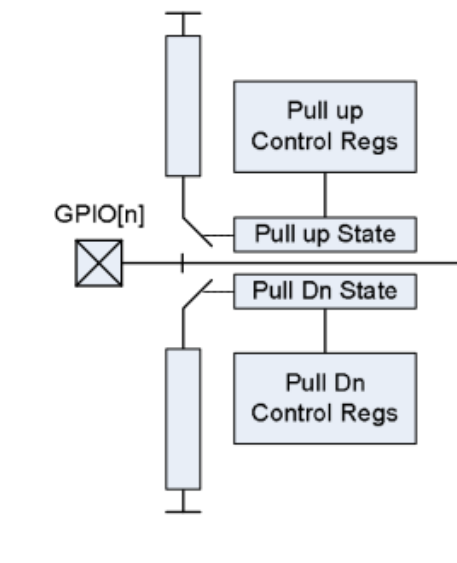
A digital signal is binary, existing in one of two states: HIGH (1) or LOW (0). On the Raspberry Pi, these correspond to 3.3V and 0V, respectively. A critical concept for inputs is the floating state. An unconnected input pin can have an unpredictable value. To prevent this, we use pull-up or pull-down resistors. A pull-up resistor ensures the pin’s default state is HIGH, while a pull-down ensures it is LOW. The gpiod library allows you to configure these internal resistors when you request a line.
The I2C Bus: A Two-Wire Dialogue
As embedded systems become more complex, the need to communicate with multiple peripheral devices—such as sensors, memory chips, and display controllers—becomes paramount. The Inter-Integrated Circuit (I2C) protocol is a workhorse in the embedded world, prized for its simplicity and ability to connect multiple devices using just two wires: Serial Data Line (SDA) and Serial Clock Line (SCL).
I2C is a master-slave protocol. The master device (the Raspberry Pi) initiates and controls all communication and provides the clock signal. Slave devices (sensors, etc.) listen on the bus and only respond when addressed by the master. Every slave device has a unique 7-bit address, which allows multiple devices to share the same two wires. When the master wants to communicate, it broadcasts a start condition, the slave’s address, and a read/write bit. Only the matching slave responds with an acknowledgement (ACK). Data is then transferred, synchronized by the SCL clock, and the transaction ends with a stop condition.
The smbus2 Python library is built on top of the Linux kernel’s I2C driver, which exposes I2C buses as device files like /dev/i2c-1. The “SMBus” (System Management Bus) is a specific implementation of the I2C protocol, and smbus2 provides convenient functions like read_byte_data() and write_byte_data(), abstracting away the low-level file I/O and letting the developer focus on the data being transferred.

The SPI Bus: High-Speed Serial Communication
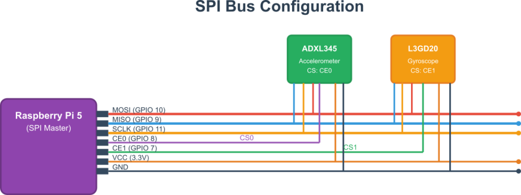
For applications requiring higher data throughput, such as high-resolution displays or fast Analog-to-Digital Converters (ADCs), the Serial Peripheral Interface (SPI) protocol is often preferred. SPI is a master-slave protocol that uses four wires:
- SCLK (Serial Clock): Clock signal from the master.
- MOSI (Master Out, Slave In): Data from master to slave.
- MISO (Master In, Slave Out): Data from slave to master.
- CS/SS (Chip Select / Slave Select): A dedicated line for each slave. The master pulls this line LOW to select a specific slave.
The use of separate data lines (MOSI and MISO) allows SPI to be full-duplex (sending and receiving data simultaneously). The dedicated Chip Select line simplifies the protocol and contributes to its high speed.
The spidev Python library provides a direct interface to the Linux SPI driver (/dev/spidevB.C, where B is the bus number and C is the chip select number). It gives the developer fine-grained control over SPI parameters like communication speed and mode (clock polarity/phase). Its core function, xfer2(), elegantly handles the full-duplex nature of the protocol by sending a list of bytes and returning the list of bytes received during the transaction.
Practical Examples
This section provides hands-on examples. Ensure your Raspberry Pi 5 is running the latest Raspberry Pi OS.
Tip: It’s a good practice to create a dedicated directory for your projects. Use
mkdir ~/python-hw-projectsandcd ~/python-hw-projectsto get started.
First, install the necessary libraries and tools:
sudo apt-get update
sudo apt-get install -y python3-pip gpiod python3-gpiod
pip install smbus2 spidev
Example 1: GPIO Input and Output with gpiod
This example demonstrates how to read a button press (input) and control an LED (output) using the modern gpiod library.
Hardware Integration
- 1x LED (any color)
- 1x 330Ω resistor
- 1x Tactile push button
- Jumper wires & Breadboard
Wiring:
- Connect the LED’s anode (longer leg) to GPIO 17 (Physical Pin 11).
- Connect the LED’s cathode (shorter leg) to one leg of the 330Ω resistor.
- Connect the other leg of the resistor to a Ground (GND) pin (e.g., Physical Pin 9).
- Connect one side of the push button to GPIO 27 (Physical Pin 13).
- Connect the other side of the push button to a Ground (GND) pin (e.g., Physical Pin 14).
Warning: Always connect a current-limiting resistor in series with an LED. Connecting an LED directly to a GPIO pin can draw too much current and damage both the LED and the Raspberry Pi.
Code Snippet: button_led_gpiod.py
Create a new file named button_led_gpiod.py. This script will light the LED while the button is pressed.
import gpiod
import time

# --- Pin Definitions ---
# On Raspberry Pi 5, the main GPIO pins are on chip 4.
# You can verify this with the `gpiodetect` command.
GPIO_CHIP = 'gpiochip4'
# BCM numbers are used as the line offsets.
LED_LINE_OFFSET = 17
BUTTON_LINE_OFFSET = 27

def main():
    """Main function to setup pins and run the loop using gpiod."""
    print("Starting button and LED example with gpiod...")

    # The 'with' statement ensures that the chip is properly closed.
    with gpiod.Chip(GPIO_CHIP) as chip:
        # Request the LED line as an output.
        # The consumer name is a string that identifies your application.
        led_line = chip.get_line(LED_LINE_OFFSET)
        led_line.request(consumer="button_led.py", type=gpiod.LINE_REQ_DIR_OUT)

        # Request the button line as an input with a pull-up resistor.
        button_line = chip.get_line(BUTTON_LINE_OFFSET)
        button_line.request(
            consumer="button_led.py",
            type=gpiod.LINE_REQ_DIR_IN,
            flags=gpiod.LINE_REQ_FLAG_PULL_UP
        )

        print("Setup complete. Press the button to light up the LED. Press CTRL+C to exit.")

        try:
            # --- Main Loop ---
            while True:
                # Read the state of the button.
                # With a pull-up, the value is 1 (HIGH) when not pressed,
                # and 0 (LOW) when pressed (connected to ground).
                button_state = button_line.get_value()

                if button_state == 0:
                    # Button is pressed, turn LED ON (set line to 1)
                    led_line.set_value(1)
                else:
                    # Button is not pressed, turn LED OFF (set line to 0)
                    led_line.set_value(0)

                # A small delay to prevent the script from using 100% CPU
                time.sleep(0.01)

        except KeyboardInterrupt:
            # This block will run when the user presses CTRL+C
            print("\nExiting program.")
        finally:
            # The 'with' statement handles cleanup automatically by releasing the lines.
            print("GPIO lines released.")

if __name__ == '__main__':
    main()
Build and Run
- Save the code file.
- Run the script:
python3 button_led_gpiod.py - Press the button. The LED should light up. Release it, and the LED should turn off.
- Press
CTRL+Cto stop the script. Thewithblock ensures the GPIO lines are automatically released.
Example 2: Reading an I2C Sensor with smbus2
This example shows how to read temperature, pressure, and humidity from a BME280 sensor.
Hardware Integration
- 1x BME280 Sensor Module (ensure it’s a 3.3V compatible version)
- Jumper wires
Wiring:
- Connect the sensor’s VIN pin to a 3.3V pin on the Raspberry Pi (Physical Pin 1).
- Connect the sensor’s GND pin to a GND pin (Physical Pin 6).
- Connect the sensor’s SCL pin to the Raspberry Pi’s I2C SCL pin (GPIO 3, Physical Pin 5).
- Connect the sensor’s SDA pin to the Raspberry Pi’s I2C SDA pin (GPIO 2, Physical Pin 3).
Configuration Steps
1. Enable the I2C interface. Run sudo raspi-config, navigate to Interface Options -> I2C, and select <Yes> to enable it.
2. Reboot if prompted.
3. Install a helper tool and verify the sensor is detected.
sudo apt-get install -y i2c-tools
# Run the detection tool on I2C bus 1
sudo i2cdetect -y 1
4. You should see a table of I2C addresses. The BME280 typically appears at address 76 or 77. If you see one of these numbers, the sensor is correctly wired.
Code Snippet: read_bme280.py
Interacting with the BME280 involves reading calibration data and then raw sensor values, which are then converted using a formula from the datasheet. For simplicity, we will use a pre-existing library that handles these complex calculations but uses smbus2 under the hood.
First, install the library: pip install bme280
import smbus2
import bme280
import time

# --- I2C Setup ---
# Define the I2C bus number (1 for modern Raspberry Pi models)
PORT = 1
# BME280 address, 0x76 or 0x77. Check with `i2cdetect -y 1`
ADDRESS = 0x76

def main():
    """Main function to initialize the sensor and read data."""
    print("Reading data from BME280 sensor...")

    try:
        # Initialize the smbus2 object for the I2C bus
        bus = smbus2.SMBus(PORT)

        # Load the calibration parameters from the sensor
        # The bme280 library uses the smbus2 object to communicate
        calibration_params = bme280.load_calibration_params(bus, ADDRESS)

        print("Sensor initialized. Reading data every 2 seconds. Press CTRL+C to exit.")

        # --- Main Loop ---
        while True:
            # The bme280.sample() function reads the raw data and applies
            # the calibration parameters to return compensated values.
            data = bme280.sample(bus, ADDRESS, calibration_params)

            # The data object contains timestamp, temperature, pressure, and humidity
            temp_c = data.temperature
            pressure_hpa = data.pressure
            humidity_percent = data.humidity

            # Print the formatted data
            print(f"Temperature: {temp_c:.2f} °C")
            print(f"Pressure: {pressure_hpa:.2f} hPa")
            print(f"Humidity: {humidity_percent:.2f} %")
            print("-" * 20)

            time.sleep(2)

    except FileNotFoundError:
        print(f"Error: I2C bus {PORT} not found. Ensure I2C is enabled in raspi-config.")
    except OSError as e:
        print(f"OS Error: {e}. Check I2C connection and address. Is the sensor at 0x{ADDRESS:02x}?")
    except KeyboardInterrupt:
        print("\nExiting program.")
    finally:
        print("Program finished.")

if __name__ == '__main__':
    main()
Build and Run
- Save the code file.
- Run the script:
python3 read_bme280.py - You should see the current temperature, pressure, and humidity printed to the console every two seconds.
- Press
CTRL+Cto exit.
Example 3: Reading an ADC with spidev
This example uses an MCP3008 Analog-to-Digital Converter (ADC) to read a voltage from a potentiometer. This allows the Raspberry Pi, which has no native analog inputs, to measure analog signals.
Hardware Integration
- 1x MCP3008 ADC IC
- 1x 10kΩ Potentiometer
- Jumper wires
- Breadboard
Wiring:
- Connect MCP3008 VDD and VREF to a 3.3V pin.
- Connect MCP3008 AGND and DGND to a GND pin.
- Connect MCP3008 CLK to Raspberry Pi SPI SCLK (GPIO 11, Physical Pin 23).
- Connect MCP3008 DOUT to Raspberry Pi SPI MISO (GPIO 9, Physical Pin 21).
- Connect MCP3008 DIN to Raspberry Pi SPI MOSI (GPIO 10, Physical Pin 19).
- Connect MCP3008 CS/SHDN to Raspberry Pi SPI CE0 (GPIO 8, Physical Pin 24).
- Connect the potentiometer’s outer two pins to 3.3V and GND.
- Connect the potentiometer’s middle pin (wiper) to CH0 on the MCP3008.
Configuration Steps
- Enable the SPI interface. Run
sudo raspi-config, navigate toInterface Options->SPI, and select<Yes>to enable it. - Reboot if prompted.
- Verify the SPI device is present:
ls /dev/spidev*. You should see/dev/spidev0.0.
Code Snippet: read_mcp3008.py
import spidev
import time

# --- SPI Setup ---
# Create a new spidev object
spi = spidev.SpiDev()
# Open the SPI device 0.0 (Bus 0, Chip Select 0)
spi.open(0, 0)

# Set SPI speed and mode
spi.max_speed_hz = 1000000
spi.mode = 0

def read_adc(channel):
    """
    Reads a single value from the specified ADC channel (0-7).
    """
    if not 0 <= channel <= 7:
        raise ValueError("ADC channel must be an integer between 0 and 7.")

    # The MCP3008 expects a 3-byte command.
    # Byte 1: Start bit (always 1)
    # Byte 2: Configuration bits (single-ended, channel number)
    # Byte 3: "Don't care" byte
    # The command to read from a channel is [1, (8 + channel) << 4, 0]
    command = [1, (8 + channel) << 4, 0]

    # The xfer2 method sends the command and returns the received data
    adc_data = spi.xfer2(command)

    # The result is a 10-bit number, spread across the last two bytes received.
    # We need to combine them to get the final value.
    # adc_data[1] contains the two most significant bits.
    # adc_data[2] contains the eight least significant bits.
    adc_value = ((adc_data[1] & 3) << 8) + adc_data[2]
    return adc_value

def main():
    """Main function to read from the ADC in a loop."""
    print("Reading from MCP3008 ADC (Channel 0)...")
    print("Turn the potentiometer to see the value change. Press CTRL+C to exit.")

    try:
        while True:
            # Read the value from channel 0
            value = read_adc(0)

            # Convert the 10-bit value (0-1023) to a voltage (0-3.3V)
            voltage = (value * 3.3) / 1023

            # Print the raw value and the calculated voltage
            print(f"Raw ADC Value: {value:4d} | Voltage: {voltage:.2f}V")

            time.sleep(0.5)

    except KeyboardInterrupt:
        print("\nExiting program.")
    finally:
        # Close the SPI connection
        spi.close()
        print("SPI connection closed.")

if __name__ == '__main__':
    main()
Build and Run
- Save the code file.
- Run the script:
python3 read_mcp3008.py - You will see a raw value between 0 and 1023 and the corresponding voltage.
- Turn the potentiometer knob. The values should change in real-time.
- Press
CTRL+Cto exit.
Common Mistakes & Troubleshooting
Exercises
- Traffic Light Controller:
- Objective: Create a simple traffic light sequence using
gpiod. - Hardware: 3x LEDs (red, yellow, green), 3x 330Ω resistors.
- Guidance: Write a Python script using
gpiodthat requests three output lines. Cycle through the lights: Green for 5 seconds, then Yellow for 2 seconds, then Red for 5 seconds. The sequence should repeat indefinitely until the user pressesCTRL+C. Use awithblock to manage the chip and request all three lines at the start. - Verification: Observe the LEDs to confirm they light up in the correct sequence and for the specified durations.
- Objective: Create a simple traffic light sequence using
- I2C Device Scanner:
- Objective: Write a Python script that scans the I2C bus and prints the addresses of any connected devices. (This exercise is unchanged.)
- Hardware: Any I2C device.
- Guidance: Use the
smbus2library. Loop through addresses 0x03 to 0x77. Use atry...exceptblock to attempt communication (bus.write_quick(address)). If it succeeds, a device is present. - Verification: Compare your script’s output to
sudo i2cdetect -y 1.
- Interrupt-Driven Button Counter:
- Objective: Write an efficient button-press counter using
gpiodevent monitoring. - Hardware: 1x Push button.
- Guidance: Request a button line with
type=gpiod.LINE_REQ_DIR_IN,flags=gpiod.LINE_REQ_FLAG_PULL_UP, and addgpiod.LINE_REQ_FLAG_ACTIVE_LOW. Use theline.event_wait()method inside a loop. This method will block the script until an event (a button press) occurs. When it unblocks, increment a counter and print it. - Verification: Run the script. The console should only print a new count each time you press the button. The script should not consume high CPU, as it’s event-driven.
- Objective: Write an efficient button-press counter using
- SPI Loopback Test:
- Objective: Verify the SPI interface is working correctly. (This exercise is unchanged.)
- Hardware: A single jumper wire.
- Guidance: Connect the Raspberry Pi’s MOSI pin (GPIO 10) directly to its MISO pin (GPIO 9). Use
spidevto send a list of bytes withspi.xfer2()and check if the returned list is identical. - Verification: The sent and received data printed to the console should match exactly.
Summary
This chapter provided a practical introduction to modern hardware control on the Raspberry Pi 5 using Python, demonstrating how high-level languages can accelerate embedded development.
- Python’s Role: We established that Python’s primary advantages in embedded Linux are its high-level abstractions, extensive libraries, and rapid development capabilities.
- GPIO Control: We explored the fundamentals of the Linux character device interface and used the
gpiodlibrary to control digital inputs and outputs, emphasizing modern best practices like identifying chips, requesting lines, and usingwithstatements for automatic resource management. - I2C Communication: We delved into the two-wire I2C protocol and used the
smbus2library to easily read data from a complex peripheral device. - SPI Communication: We covered the high-speed, four-wire SPI protocol and used the
spidevlibrary to interface with an ADC, enabling the Raspberry Pi to read analog signals. - Practical Skills: Through hands-on examples and troubleshooting guides, you have gained the skills to wire components, configure system interfaces, write robust Python control scripts, and debug common hardware-related issues using modern tools.
Further Reading
- Raspberry Pi Documentation – GPIO: The official documentation for the Raspberry Pi’s hardware specifications.
libgpiodProject Page: The official source for thelibgpiodlibrary, including links to its source code and mailing list.- The I2C Protocol Specification: The official specification from NXP (formerly Philips).
- Linux Kernel I2C Documentation: For understanding how I2C is implemented at the OS level.
smbus2Documentation: The official documentation for thesmbus2library.- An Introduction to SPI – SparkFun: A clear, practical tutorial on the SPI protocol.
- Linux Kernel SPI Documentation: The kernel documentation for the SPI subsystem and the
spidevuser-space interface.
