
Chapter 165: Pulse Counter (PCNT) Module
Chapter Objectives
By the end of this chapter, you will be able to:
- Understand the architecture and working principles of the ESP32 series Pulse Counter (PCNT) module.
- Configure and initialize a PCNT unit and its channels using ESP-IDF v5.x.
- Count pulses from external digital signals.
- Implement basic frequency measurement of a pulse train.
- Understand how to configure PCNT for different counting modes (e.g., edge detection, level control).
- Interface a quadrature rotary encoder with the PCNT module.
- Recognize differences in PCNT capabilities across various ESP32 variants.
- Identify common pitfalls and troubleshoot PCNT applications.
Introduction
In many embedded systems, the need to count external events, measure frequencies, or determine the position and speed of rotating machinery is paramount. These events are often represented as digital pulses. The Pulse Counter (PCNT) module in ESP32 microcontrollers is a dedicated hardware peripheral designed specifically for these tasks. It can operate autonomously, counting pulses on GPIO pins without significant CPU intervention, making it highly efficient.
Applications for the PCNT module are diverse, ranging from reading rotary encoders for user interfaces or motor control, measuring flow rates from sensors (e.g., water or gas meters), counting RPM of a motor, to capturing signals from various other pulse-generating devices. Understanding and utilizing the PCNT module effectively unlocks a powerful capability for interacting with the physical world. This chapter will guide you through its theory, configuration, and practical application.
Theory
The Pulse Counter (PCNT) module is a peripheral that counts the number of rising and/or falling edges of an input signal. Each ESP32 variant comes with one or more PCNT units, which are independent hardware counters.
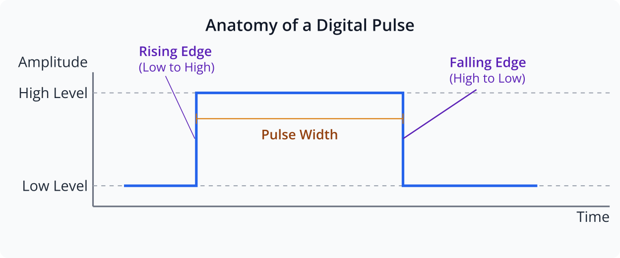
What is a Pulse?
In digital electronics, a pulse is a rapid, transient change in the amplitude of a signal from a baseline value to a higher or lower value, followed by a rapid return to the baseline value. We are typically interested in the transitions, known as edges:
- Rising Edge: Transition from a low logic level to a high logic level.
- Falling Edge: Transition from a high logic level to a low logic level.
The PCNT module on ESP32 series chips consists of several independent PCNT units. Each unit is essentially a counter that can be configured to increment or decrement based on events on one or two input GPIO pins.
Key components and concepts of a PCNT unit:
- Input Pins:
- Pulse Input (Edge Input): The primary GPIO pin where the pulses to be counted are received.
- Control Input (Level Input): An optional secondary GPIO pin whose logic level can control the counting behavior (e.g., direction of count, enable/disable counting).
- Signal Conditioning:
- Input Filter: The PCNT module includes a configurable digital filter to debounce input signals or reject noise. This is crucial for reliable counting in noisy environments or with mechanical inputs like buttons or encoders. The filter typically works by requiring the signal to remain stable for a certain number of APB clock cycles.
- Counter Register:
- A signed 16-bit register that holds the current pulse count. It can be read by the CPU at any time or cleared.
- Counting Modes:The behavior of the counter (increment, decrement, or no change) can be configured based on the edges of the pulse input signal and the state of the control input signal.
pcnt_channel_edge_action_t: Defines what the counter should do on a positive or negative edge of the pulse input pin. Actions includePCNT_CHANNEL_EDGE_ACTION_INCREASE(increment),PCNT_CHANNEL_EDGE_ACTION_DECREASE(decrement), orPCNT_CHANNEL_EDGE_ACTION_HOLD(do nothing).pcnt_channel_level_action_t: Defines what the counter should do when the control input pin is at a high or low level, in conjunction with an edge on the pulse input. Actions includePCNT_CHANNEL_LEVEL_ACTION_KEEP(no effect on direction),PCNT_CHANNEL_LEVEL_ACTION_INVERSE(invert the action defined by edge detection), orPCNT_CHANNEL_LEVEL_ACTION_HOLD(pause counting).
- Comparators and Events:Each PCNT unit has programmable comparators that can trigger events or interrupts when the counter value reaches specific thresholds:
- Zero Crossing: When the counter value crosses zero.
- Limit Values:
high_limitandlow_limit. When the counter reaches these values, it can trigger an event and optionally saturate (stop counting) or roll over. - Threshold Values:
thresh0_valandthresh1_val. These are two general-purpose threshold values that can trigger events.
- Interrupts:Events generated by the comparators (zero crossing, limits, thresholds) can be configured to trigger CPU interrupts, allowing for timely software intervention without constant polling.
%%{init: {'fontFamily': 'Open Sans'}}%%
graph TD
    subgraph "Input Stage"
        direction LR
        P_IN[("Pulse Input<br>(edge_gpio_num)")]
        C_IN[("Control Input<br>(level_gpio_num)")]

        P_IN -- "Signal" --> FILTER("/<i>Glitch Filter</i>/");
        C_IN -- "Level" --> E_L_LOGIC["Edge & Level<br>Detection Logic"];
        FILTER -- "Filtered Signal" --> E_L_LOGIC;
    end

    subgraph "Counter & Control Logic"
        direction TB
        E_L_LOGIC -- "Increment/Decrement/Hold" --> COUNTER[("16-bit Signed<br>Counter Register")];
    end

    subgraph "Comparator & Event Stage"
        direction RL
        COUNTER -- "Current Count" --> COMPARATORS;

        subgraph "Comparators"
            direction TB
            ZERO("Zero<br>Crossing")
            H_LIM("High Limit")
            L_LIM("Low Limit")
            TH0("Threshold 0")
            TH1("Threshold 1")
        end

        COMPARATORS -- "Match" --> EVENTS[("Event Generation")];
    end

    subgraph "Output Stage"
        direction TB
        CPU["CPU /<br>ESP-IDF Driver"]
        EVENTS -- "Interrupt Request" --> CPU;
        COUNTER -- "Read/Clear" --> CPU;
    end

    %% Styling
    classDef default fill:#F9FAFB,stroke:#E5E7EB,stroke-width:1px,color:#374151;
    classDef inputNode fill:#DBEAFE,stroke:#2563EB,stroke-width:1px,color:#1E40AF;
    classDef logicNode fill:#FEF3C7,stroke:#D97706,stroke-width:1px,color:#92400E;
    classDef counterNode fill:#EDE9FE,stroke:#5B21B6,stroke-width:2px,color:#5B21B6;
    classDef eventNode fill:#FEE2E2,stroke:#DC2626,stroke-width:1px,color:#991B1B;
    classDef cpuNode fill:#D1FAE5,stroke:#059669,stroke-width:2px,color:#065F46;

    class P_IN,C_IN,FILTER inputNode;
    class E_L_LOGIC logicNode;
    class COUNTER counterNode;
    class COMPARATORS,ZERO,H_LIM,L_LIM,TH0,TH1 eventNode;
    class EVENTS eventNode;
    class CPU cpuNode;
ESP-IDF v5.x PCNT Driver
In ESP-IDF v5.x, the PCNT driver is organized around two main handles:
pcnt_unit_handle_t: Represents a hardware PCNT unit.pcnt_channel_handle_t: Represents a configuration for how a PCNT unit responds to signals on specific GPIOs.
Configuration Steps:
%%{init: {'fontFamily': 'Open Sans'}}%%
flowchart TD
    A(Start: Configure PCNT)
    A --> B{"pcnt_new_unit()"};
    B -- "Set high/low limits" --> C{"pcnt_new_channel()"};
    C -- "Assign edge & level GPIOs" --> D{"pcnt_channel_set_edge_action()"};
    D -- "Define +/- edge behavior" --> E{"pcnt_channel_set_level_action()"};
    E -- "Define high/low level behavior" --> F{Optional:<br>Set Filter/Watchdog?};
    F -- "Yes" --> G["pcnt_unit_set_glitch_filter()<br>pcnt_unit_add_watch_dog()"];
    G --> H{Optional:<br>Register Callbacks?};
    F -- "No" --> H;
    H -- "Yes" --> I["pcnt_unit_register_event_callbacks()"];
    I --> J;
    H -- "No" --> J;
    J["pcnt_unit_enable()"] --> K["pcnt_unit_clear_count()"];
    K --> L["pcnt_unit_start()"];
    L --> M(End: PCNT Running);

    %% Styling
    classDef startNode fill:#EDE9FE,stroke:#5B21B6,stroke-width:2px,color:#5B21B6;
    classDef processNode fill:#DBEAFE,stroke:#2563EB,stroke-width:1px,color:#1E40AF;
    classDef decisionNode fill:#FEF3C7,stroke:#D97706,stroke-width:1px,color:#92400E;
    classDef optionalNode fill:#E5E7EB,stroke:#6B7280,stroke-width:1px,color:#374151;
    classDef endNode fill:#D1FAE5,stroke:#059669,stroke-width:2px,color:#065F46;

    class A,L,M startNode;
    class B,C,D,E,J,K processNode;
    class F,H decisionNode;
    class G,I optionalNode;
    class M endNode;
- Allocate a PCNT Unit:
- Use
pcnt_new_unit()with apcnt_unit_config_tstructure. pcnt_unit_config_t:low_limit: Minimum count value before an event/action.high_limit: Maximum count value before an event/action.flags.accum_count: If set, the counter will accumulate even after hitting high/low limits (overflow/underflow). Otherwise, it saturates.
- Use
- Allocate a PCNT Channel:
- Use
pcnt_new_channel()with apcnt_channel_config_tstructure. This associates GPIO pins with the allocated PCNT unit. pcnt_channel_config_t:edge_gpio_num: GPIO for the primary pulse input.level_gpio_num: GPIO for the control/direction input (can be -1 if not used).flags.invert_edge_input: Invert logic of edge input.flags.invert_level_input: Invert logic of level input.
- Use
- Configure Channel Actions:
pcnt_channel_set_edge_action(): Define how the counter reacts to rising (PCNT_POS_MODE_...) and falling (PCNT_NEG_MODE_...) edges on theedge_gpio_num.pcnt_channel_set_level_action(): Define how the state oflevel_gpio_num(high or low) influences the counting based on edges fromedge_gpio_num.
- Add Watchdog (Optional but Recommended):
pcnt_unit_add_watch_dog(): Set a timeout. If no pulses are received within this period, a watchdog event (PCNT_UNIT_EVENT_WATCHDOG) is triggered. This is useful for detecting stalled sensors.
- Register Event Callbacks (Optional):
pcnt_unit_register_event_callbacks(): Register functions to be called on specific events likePCNT_UNIT_EVENT_HIGH_LIMIT,PCNT_UNIT_EVENT_LOW_LIMIT,PCNT_UNIT_EVENT_ZERO,PCNT_UNIT_EVENT_THRES0,PCNT_UNIT_EVENT_THRES1,PCNT_UNIT_EVENT_WATCHDOG.- Callbacks run in ISR context, so they must be fast and not call blocking functions. Use
IRAM_ATTRfor the callback function.
- Enable and Start:
pcnt_unit_enable(): Enable the PCNT unit (clocks, etc.).pcnt_unit_start(): Start counting. Before starting, it’s good practice topcnt_unit_clear_count().
- Operations:
pcnt_unit_get_count(): Read the current count.pcnt_unit_clear_count(): Reset the count to zero.pcnt_unit_stop(): Stop counting.pcnt_unit_disable(): Disable the PCNT unit.
- Deinitialization:
pcnt_unit_remove_watch_dog()pcnt_del_channel()pcnt_del_unit()
Frequency Measurement using PCNT
There are two primary methods to measure frequency using a pulse counter:
| Feature | Method 1: Count Pulses over Fixed Time | Method 2: Measure Time for Fixed Pulses |
|---|---|---|
| Concept | Count pulses (N) during a fixed gate time (T). | Measure time (T) to receive a fixed number of pulses (N). |
| Formula | Frequency = N / T | Frequency = N / T |
| Primary Hardware | PCNT + General Purpose Timer (e.g., esp_timer) | PCNT (with threshold event) + High-Resolution Timer |
| Best For | Low to medium frequencies. Simpler implementation. | Medium to high frequencies. Higher potential precision. |
| Pros | – Easy to implement. – Good for a wide frequency range. – Less susceptible to single-period jitter. |
– Fast updates for high frequencies. – Can be more accurate as it directly measures the signal’s period. |
| Cons | – Slow updates for low frequencies (requires long gate time for accuracy). – Accuracy limited by gate time precision. |
– More complex to implement (requires managing two timers). – Can be inaccurate for very low frequencies or bursty signals. |
- Count Pulses over a Fixed Time Period (Gated Counting):
- Configure the PCNT to count incoming pulses.
- Use a separate timer (e.g.,
esp_timer) to define a fixed time interval (the “gate time,” e.g., 1 second). - When the gate time elapses:
- Read the pulse count (N) from the PCNT register.
- Calculate frequency:
Frequency = N / Gate_Time_Seconds. - Clear the PCNT counter.
- Repeat.
- This method is simpler to implement and suitable for a wide range of frequencies. The accuracy depends on the stability of the gate time and the number of pulses counted. Longer gate times yield better accuracy for lower frequencies.
- Measure Time for a Fixed Number of Pulses:
- Configure the PCNT to generate an event (e.g., threshold interrupt) after a specific number of pulses (N) have been counted.
- Start a high-resolution timer when counting begins (or upon the first pulse).
- Stop the timer when the PCNT event for N pulses occurs. Let this measured time be T.
- Calculate frequency:
Frequency = N / T_Seconds. - This method can be more accurate for higher frequencies, as it measures the period of multiple pulses directly.
This chapter will focus on the first method for its simplicity in the practical example.
Practical Examples
Let’s put theory into practice with some code examples. Ensure you have ESP-IDF v5.x set up with VS Code and the Espressif IDF extension.
Project Setup
- Create a new ESP-IDF project in VS Code or use an existing one.
- Ensure your
main/CMakeLists.txtincludes the necessary components:idf_component_register(SRCS "main.c" INCLUDE_DIRS "." REQUIRES driver esp_log esp_timer) - In
sdkconfig.defaults(or viamenuconfig), you might want to enable logging if not already:CONFIG_LOG_DEFAULT_LEVEL_INFO=y CONFIG_LOG_MAXIMUM_LEVEL_VERBOSE=y
Example 1: Basic Pulse Counting
This example demonstrates how to count rising edges on a GPIO pin. You can generate pulses by connecting a push button (with a pull-up or pull-down resistor and debouncing capacitor) or by toggling another GPIO pin connected to the PCNT input.
Hardware Setup:
- Connect a pulse source to GPIO4 (or any other suitable GPIO). For testing, you can use a jumper wire to momentarily connect GPIO4 to 3.3V (if GPIO4 is configured with an internal pull-down) or GND (if configured with an internal pull-up). A debounced button is better.
main/main.c:
#include <stdio.h>
#include "freertos/FreeRTOS.h"
#include "freertos/task.h"
#include "driver/pulse_cnt.h"
#include "driver/gpio.h"
#include "esp_log.h"
static const char *TAG = "PCNT_BASIC_EXAMPLE";
#define PCNT_INPUT_GPIO 4 // GPIO pin for pulse input
#define PCNT_HIGH_LIMIT 10000 // Example high limit for the counter
#define PCNT_LOW_LIMIT -10000// Example low limit for the counter
// Callback for PCNT events (optional, runs in ISR context)
// IRAM_ATTR helps to place the function in IRAM for faster execution from ISR
static bool IRAM_ATTR pcnt_event_callback(pcnt_unit_handle_t unit, const pcnt_watch_event_data_t *edata, void *user_ctx)
{
BaseType_t high_task_woken = pdFALSE;
// For this basic example, we'll just log from a task, not directly in ISR
// In a real application, you might signal a task here
ESP_DRAM_LOGI(TAG, "PCNT event: %d", edata->watch_point_event_type);
return (high_task_woken == pdTRUE); // Return true if a higher priority task was woken
}
void app_main(void)
{
ESP_LOGI(TAG, "Initializing PCNT unit");
// 1. Configure the PCNT unit
pcnt_unit_config_t unit_config = {
.high_limit = PCNT_HIGH_LIMIT,
.low_limit = PCNT_LOW_LIMIT,
// .flags.accum_count = true, // Uncomment to allow counter to accumulate beyond limits (overflow/underflow)
};
pcnt_unit_handle_t pcnt_unit = NULL;
ESP_ERROR_CHECK(pcnt_new_unit(&unit_config, &pcnt_unit));
// 2. Configure the PCNT channel
pcnt_channel_config_t channel_config = {
.edge_gpio_num = PCNT_INPUT_GPIO,
.level_gpio_num = -1, // Set to -1 if not using level control
.flags.invert_edge_input = false, // Don't invert edge input
.flags.invert_level_input = false, // Don't invert level input (if used)
// .flags.io_loop_back = true, // For debug: connect output to input
};
pcnt_channel_handle_t pcnt_channel = NULL;
ESP_ERROR_CHECK(pcnt_new_channel(pcnt_unit, &channel_config, &pcnt_channel));
// 3. Set edge and level actions for the channel
// For basic pulse counting, we usually increment on one edge type.
// Increment on positive edge, hold on negative edge
ESP_ERROR_CHECK(pcnt_channel_set_edge_action(pcnt_channel,
PCNT_CHANNEL_EDGE_ACTION_INCREASE, // Action on positive edge
PCNT_CHANNEL_EDGE_ACTION_HOLD)); // Action on negative edge (could be DECREASE or HOLD)
// No level control used in this basic example, so default actions are fine.
// ESP_ERROR_CHECK(pcnt_channel_set_level_action(pcnt_channel,
// PCNT_CHANNEL_LEVEL_ACTION_KEEP, // Action when level input is high
// PCNT_CHANNEL_LEVEL_ACTION_KEEP)); // Action when level input is low
// Optional: Add a filter to ignore glitches
// pcnt_glitch_filter_config_t filter_config = {
// .max_glitch_ns = 1000, // Glitches shorter than 1000ns will be ignored
// };
// ESP_ERROR_CHECK(pcnt_unit_set_glitch_filter(pcnt_unit, &filter_config));
// ESP_LOGI(TAG, "Filter enabled, max_glitch_ns: %d", filter_config.max_glitch_ns);
// Optional: Register event callbacks
pcnt_event_callbacks_t cbs = {
.on_reach_high_limit = pcnt_event_callback,
.on_reach_low_limit = pcnt_event_callback,
.on_reach_zero = pcnt_event_callback,
};
ESP_ERROR_CHECK(pcnt_unit_register_event_callbacks(pcnt_unit, &cbs, NULL));
ESP_LOGI(TAG, "Event callbacks registered");
// 4. Enable and start the PCNT unit
ESP_ERROR_CHECK(pcnt_unit_enable(pcnt_unit));
ESP_LOGI(TAG, "PCNT unit enabled");
ESP_ERROR_CHECK(pcnt_unit_clear_count(pcnt_unit)); // Clear count before starting
ESP_LOGI(TAG, "PCNT count cleared");
ESP_ERROR_CHECK(pcnt_unit_start(pcnt_unit));
ESP_LOGI(TAG, "PCNT unit started");
int current_count = 0;
while (1) {
ESP_ERROR_CHECK(pcnt_unit_get_count(pcnt_unit, ¤t_count));
ESP_LOGI(TAG, "Current PCNT count: %d", current_count);
// Example: Clear count when it reaches a certain value (e.g., 10)
// if (current_count >= 10) {
// ESP_LOGI(TAG, "Count reached 10, clearing count.");
// ESP_ERROR_CHECK(pcnt_unit_clear_count(pcnt_unit));
// }
vTaskDelay(pdMS_TO_TICKS(1000)); // Read every second
}
// Cleanup (not reached in this example)
// ESP_ERROR_CHECK(pcnt_unit_stop(pcnt_unit));
// ESP_ERROR_CHECK(pcnt_unit_disable(pcnt_unit));
// ESP_ERROR_CHECK(pcnt_del_channel(pcnt_channel));
// ESP_ERROR_CHECK(pcnt_del_unit(pcnt_unit));
}
Build Instructions:
- Open your ESP-IDF project in VS Code.
- Ensure the ESP-IDF extension is active and configured.
- Click the “Build” button (or run
idf.py buildin the ESP-IDF terminal).
Run/Flash/Observe Steps:
- Connect your ESP32 board to your computer.
- Click the “Flash” button (or run
idf.py -p /dev/ttyUSB0 flashreplacing/dev/ttyUSB0with your serial port). - Click the “Monitor” button (or run
idf.py monitor). - Apply pulses to GPIO4. You should see the “Current PCNT count” log messages updating with the number of pulses detected. If you configured event callbacks, you might see logs from there too when limits are reached.
Tip: For reliable button input, use a 10kΩ pull-up resistor from GPIO4 to 3.3V and connect the button between GPIO4 and GND. Add a 0.1µF capacitor in parallel with the button for hardware debouncing. Alternatively, use the internal pull-up/pull-down resistors:
C// Inside app_main, before PCNT setup: gpio_config_t io_conf = { .pin_bit_mask = (1ULL << PCNT_INPUT_GPIO), .mode = GPIO_MODE_INPUT, .pull_up_en = GPIO_PULLUP_ENABLE, // Or GPIO_PULLDOWN_ENABLE .pull_down_en = GPIO_PULLDOWN_DISABLE, .intr_type = GPIO_INTR_DISABLE }; gpio_config(&io_conf);Then, if using
GPIO_PULLUP_ENABLE, connect the button to GND. IfGPIO_PULLDOWN_ENABLE, connect to 3.3V. The PCNT filter (pcnt_unit_set_glitch_filter) is also highly recommended for mechanical inputs.
Example 2: Frequency Measurement (Pulses in Fixed Time)
This example measures the frequency of a signal on GPIO4 by counting pulses over a 1-second interval using esp_timer.
Hardware Setup:
- Connect a pulse source (e.g., function generator, or another ESP32 GPIO toggling at a known rate) to GPIO4.
main/main.c:
#include <stdio.h>
#include "freertos/FreeRTOS.h"
#include "freertos/task.h"
#include "driver/pulse_cnt.h"
#include "driver/gpio.h"
#include "esp_log.h"
#include "esp_timer.h" // For esp_timer

static const char *TAG = "PCNT_FREQ_EXAMPLE";

#define PCNT_INPUT_GPIO         4
#define PCNT_HIGH_LIMIT         30000 // Set a high enough limit for 1 sec
#define PCNT_LOW_LIMIT          -30000
#define GATE_TIME_MS            1000  // 1 second gate time

static pcnt_unit_handle_t pcnt_unit = NULL;

// esp_timer callback to read count and calculate frequency
static void IRAM_ATTR freq_measurement_timer_callback(void *arg)
{
    int pulse_count;
    if (pcnt_unit) { // Ensure pcnt_unit is initialized
        // 1. Get the pulse count
        if (pcnt_unit_get_count(pcnt_unit, &pulse_count) == ESP_OK) {
            // 2. Calculate frequency
            // Since GATE_TIME_MS is in milliseconds, convert to seconds for Hz
            float frequency = (float)pulse_count / (GATE_TIME_MS / 1000.0f);
            ESP_DRAM_LOGI(TAG, "Pulses in %dms: %d, Frequency: %.2f Hz", GATE_TIME_MS, pulse_count, frequency);

            // 3. Clear the PCNT counter for the next interval
            pcnt_unit_clear_count(pcnt_unit);
        }
    }
}

void app_main(void)
{
    ESP_LOGI(TAG, "Initializing PCNT for frequency measurement");

    // Configure PCNT unit
    pcnt_unit_config_t unit_config = {
        .high_limit = PCNT_HIGH_LIMIT,
        .low_limit = PCNT_LOW_LIMIT,
    };
    ESP_ERROR_CHECK(pcnt_new_unit(&unit_config, &pcnt_unit));

    // Configure PCNT channel
    pcnt_channel_config_t channel_config = {
        .edge_gpio_num = PCNT_INPUT_GPIO,
        .level_gpio_num = -1,
    };
    pcnt_channel_handle_t pcnt_channel = NULL;
    ESP_ERROR_CHECK(pcnt_new_channel(pcnt_unit, &channel_config, &pcnt_channel));

    // Set edge actions: increment on positive edge
    ESP_ERROR_CHECK(pcnt_channel_set_edge_action(pcnt_channel,
                                                 PCNT_CHANNEL_EDGE_ACTION_INCREASE,
                                                 PCNT_CHANNEL_EDGE_ACTION_HOLD));

    // Enable and start PCNT unit
    ESP_ERROR_CHECK(pcnt_unit_enable(pcnt_unit));
    ESP_ERROR_CHECK(pcnt_unit_clear_count(pcnt_unit));
    ESP_ERROR_CHECK(pcnt_unit_start(pcnt_unit));
    ESP_LOGI(TAG, "PCNT unit started for frequency measurement");

    // Configure and start esp_timer for periodic frequency calculation
    const esp_timer_create_args_t periodic_timer_args = {
        .callback = &freq_measurement_timer_callback,
        .name = "freq_measure_timer"
    };
    esp_timer_handle_t periodic_timer;
    ESP_ERROR_CHECK(esp_timer_create(&periodic_timer_args, &periodic_timer));
    // Start the timer in periodic mode, timeout in microseconds
    ESP_ERROR_CHECK(esp_timer_start_periodic(periodic_timer, GATE_TIME_MS * 1000));
    ESP_LOGI(TAG, "esp_timer started for periodic frequency updates (%d ms interval)", GATE_TIME_MS);

    // Keep main task running (or do other things)
    while (1) {
        vTaskDelay(pdMS_TO_TICKS(5000)); // Log less frequently in main task
        ESP_LOGI(TAG, "Main task alive...");
    }

    // Cleanup (not typically reached in this kind of app)
    // esp_timer_stop(periodic_timer);
    // esp_timer_delete(periodic_timer);
    // pcnt_unit_stop(pcnt_unit);
    // pcnt_unit_disable(pcnt_unit);
    // pcnt_del_channel(pcnt_channel);
    // pcnt_del_unit(pcnt_unit);
}
Build, Flash, and Run: Follow the same steps as Example 1. Apply a signal with a known frequency to GPIO4. The monitor should output the measured frequency every second.
Example 3: Quadrature Encoder Interface
Rotary encoders are common input devices. A quadrature encoder outputs two signals (Phase A and Phase B) that are 90 degrees out of phase. The PCNT module can interpret these signals to determine both the amount and direction of rotation.
We will use one PCNT unit. The edge_gpio_num will be connected to Phase A, and level_gpio_num to Phase B.
- If A leads B (e.g., A rises while B is low), count increases (clockwise).
- If B leads A (e.g., A rises while B is high), count decreases (counter-clockwise).
Hardware Setup:
- Connect Encoder Phase A to GPIO4.
- Connect Encoder Phase B to GPIO5.
- Connect Encoder Common (C) pin to GND.
- Most encoders also need pull-up resistors (e.g., 10kΩ) on Phase A and Phase B to 3.3V if not built-in.
main/main.c:
#include <stdio.h>
#include "freertos/FreeRTOS.h"
#include "freertos/task.h"
#include "driver/pulse_cnt.h"
#include "driver/gpio.h"
#include "esp_log.h"
static const char *TAG = "PCNT_ENCODER_EXAMPLE";
#define ENCODER_PHASE_A_GPIO 4 // Pulse input
#define ENCODER_PHASE_B_GPIO 5 // Level (direction) input
#define PCNT_ENCODER_HIGH_LIMIT 1000
#define PCNT_ENCODER_LOW_LIMIT -1000
// Optional: Glitch filter configuration (encoders can be noisy)
#define ENCODER_GLITCH_FILTER_NS 1000 // Ignore glitches shorter than 1us
void app_main(void)
{
ESP_LOGI(TAG, "Initializing PCNT for Quadrature Encoder");
// Configure PCNT Unit
pcnt_unit_config_t unit_config = {
.high_limit = PCNT_ENCODER_HIGH_LIMIT,
.low_limit = PCNT_ENCODER_LOW_LIMIT,
.flags.accum_count = true, // Allow accumulation for continuous rotation
};
pcnt_unit_handle_t pcnt_unit = NULL;
ESP_ERROR_CHECK(pcnt_new_unit(&unit_config, &pcnt_unit));
// Configure PCNT Channel for Phase A (pulse) and Phase B (direction)
pcnt_channel_config_t channel_config = {
.edge_gpio_num = ENCODER_PHASE_A_GPIO,
.level_gpio_num = ENCODER_PHASE_B_GPIO,
.flags.invert_edge_input = false, // Adjust if your encoder logic is inverted
.flags.invert_level_input = false, // Adjust if your encoder logic is inverted
};
pcnt_channel_handle_t pcnt_channel = NULL;
ESP_ERROR_CHECK(pcnt_new_channel(pcnt_unit, &channel_config, &pcnt_channel));
// Set edge and level actions for quadrature decoding
// For Phase A (edge_gpio_num) rising edge:
// - If Phase B (level_gpio_num) is LOW, increment count (e.g., clockwise)
// - If Phase B (level_gpio_num) is HIGH, decrement count (e.g., counter-clockwise)
ESP_ERROR_CHECK(pcnt_channel_set_edge_action(pcnt_channel,
PCNT_CHANNEL_EDGE_ACTION_DECREASE, // Action on positive edge when level input is HIGH
PCNT_CHANNEL_EDGE_ACTION_INCREASE)); // Action on positive edge when level input is LOW
// For Phase A (edge_gpio_num) falling edge (optional, depends on encoder type - some count 2x or 4x per cycle):
// - If Phase B (level_gpio_num) is HIGH, increment count
// - If Phase B (level_gpio_num) is LOW, decrement count
// This example only counts on Phase A's positive edge for simplicity (1x decoding).
// For 2x decoding, you could set similar inverted actions for the falling edge.
// For 4x decoding, you'd typically use two PCNT channels/units, one for each phase as edge input.
// The current API (pcnt_channel_set_edge_action) defines actions for positive AND negative edges of 'edge_gpio_num'
// based on the state of 'level_gpio_num'.
//
// Let's refine for typical quadrature:
// On Positive edge of A: if B is low -> INC, if B is high -> DEC
// On Negative edge of A: if B is low -> DEC, if B is high -> INC (for 2x resolution)
// For 1x resolution (count only on A's positive edge):
// Positive edge of A: if B low -> INC, if B high -> DEC
// Negative edge of A: HOLD (or KEEP if level action is used)
//
// Let's re-check API:
// `pcnt_channel_set_edge_action(channel, pos_action, neg_action)`
// `pcnt_channel_set_level_action(channel, high_action, low_action)`
// `pos_action` is action on positive edge of `edge_gpio_num`.
// `neg_action` is action on negative edge of `edge_gpio_num`.
// `high_action` is action when `level_gpio_num` is high.
// `low_action` is action when `level_gpio_num` is low.
//
// The actions specified in `set_edge_action` are modified by `set_level_action`.
// If `level_gpio_num` is high and `high_action` is `PCNT_CHANNEL_LEVEL_ACTION_INVERSE`,
// then the `pos_action` (e.g. INCREASE) becomes DECREASE.
// Standard Quadrature Setup (1x on Phase A edges, direction by Phase B):
// Phase A = edge_gpio, Phase B = level_gpio
// Action on A's positive edge: PCNT_CHANNEL_EDGE_ACTION_INCREASE
// Action on A's negative edge: PCNT_CHANNEL_EDGE_ACTION_HOLD (for 1x) or PCNT_CHANNEL_EDGE_ACTION_DECREASE (for 2x, needs adjustment below)
ESP_ERROR_CHECK(pcnt_channel_set_edge_action(pcnt_channel,
PCNT_CHANNEL_EDGE_ACTION_INCREASE, // Action for positive edge on A
PCNT_CHANNEL_EDGE_ACTION_HOLD)); // Action for negative edge on A (1x mode)
// Control action based on level of B:
// When B is high: Invert the direction of counting set by edge_action (so INC becomes DEC)
// When B is low: Keep the direction of counting set by edge_action (so INC remains INC)
ESP_ERROR_CHECK(pcnt_channel_set_level_action(pcnt_channel,
PCNT_CHANNEL_LEVEL_ACTION_INVERSE, // When B is high, invert A's edge action
PCNT_CHANNEL_LEVEL_ACTION_KEEP)); // When B is low, keep A's edge action
// This means:
// A_pos_edge, B_low: INC (original INC, B_low keeps)
// A_pos_edge, B_high: DEC (original INC, B_high inverts)
// A_neg_edge, B_low: HOLD (original HOLD, B_low keeps)
// A_neg_edge, B_high: HOLD (original HOLD, B_high inverts - but HOLD inverted is still HOLD)
// For 2x resolution (counting on both edges of A):
// ESP_ERROR_CHECK(pcnt_channel_set_edge_action(pcnt_channel,
// PCNT_CHANNEL_EDGE_ACTION_INCREASE, // Action for positive edge on A
// PCNT_CHANNEL_EDGE_ACTION_DECREASE)); // Action for negative edge on A
// ESP_ERROR_CHECK(pcnt_channel_set_level_action(pcnt_channel,
// PCNT_CHANNEL_LEVEL_ACTION_INVERSE, // When B is high, invert A's edge action
// PCNT_CHANNEL_LEVEL_ACTION_KEEP)); // When B is low, keep A's edge action
// This would give:
// A_pos_edge, B_low: INC
// A_pos_edge, B_high: DEC
// A_neg_edge, B_low: DEC
// A_neg_edge, B_high: INC
// Add glitch filter
pcnt_glitch_filter_config_t filter_config = {
.max_glitch_ns = ENCODER_GLITCH_FILTER_NS,
};
ESP_ERROR_CHECK(pcnt_unit_set_glitch_filter(pcnt_unit, &filter_config));
ESP_LOGI(TAG, "Encoder glitch filter enabled: %d ns", ENCODER_GLITCH_FILTER_NS);
// Enable, clear, and start PCNT unit
ESP_ERROR_CHECK(pcnt_unit_enable(pcnt_unit));
ESP_ERROR_CHECK(pcnt_unit_clear_count(pcnt_unit));
ESP_ERROR_CHECK(pcnt_unit_start(pcnt_unit));
ESP_LOGI(TAG, "PCNT unit started for quadrature encoder");
int current_encoder_count = 0;
int last_encoder_count = 0;
while (1) {
ESP_ERROR_CHECK(pcnt_unit_get_count(pcnt_unit, ¤t_encoder_count));
if (current_encoder_count != last_encoder_count) {
ESP_LOGI(TAG, "Encoder Count: %d", current_encoder_count);
last_encoder_count = current_encoder_count;
}
vTaskDelay(pdMS_TO_TICKS(100)); // Read every 100ms
}
}
Build, Flash, and Run: Follow the same steps. Turn your rotary encoder. The monitor should display the changing count, increasing for one direction and decreasing for the other. The high_limit and low_limit with accum_count = true allow the counter to wrap around, which is typical for relative position tracking.
Warning: The exact configuration for
pcnt_channel_set_edge_actionandpcnt_channel_set_level_actionfor quadrature encoders can be subtle and depends on the encoder’s specific output (which phase leads for which direction) and whether you want 1x, 2x, or 4x resolution. The example above implements 1x resolution (counts on one edge of Phase A, direction determined by Phase B). For 2x or 4x, more complex configurations or multiple PCNT channels/units might be needed, or careful use of both positive and negative edge actions. Always consult your encoder’s datasheet. The ESP-IDF PCNT documentation also has examples for quadrature encoders.
Variant Notes
The PCNT module is available on most ESP32 variants, but there can be differences in the number of available units and specific features.
- ESP32: Features one PCNT peripheral with 8 independent counter units. Each unit can be configured with one pulse input and one control input.
- ESP32-S2: Features one PCNT peripheral with 4 independent counter units.
- ESP32-S3: Features one PCNT peripheral with 4 independent counter units.
- ESP32-C3 (RISC-V): Features one PCNT peripheral with 4 independent counter units.
- ESP32-C6 (RISC-V): Features one PCNT peripheral with 4 independent counter units.
- ESP32-H2 (RISC-V): Features one PCNT peripheral with 4 independent counter units.
Key Considerations:
- Number of Units: The primary difference is the number of hardware counter units available (8 for original ESP32, 4 for S2, S3, C3, C6, H2). This limits how many independent pulse sources or encoders you can interface simultaneously.
- API Consistency: The ESP-IDF v5.x
driver/pulse_cnt.hAPI aims for consistency across these variants. The core configuration structures (pcnt_unit_config_t,pcnt_channel_config_t) and functions (pcnt_new_unit,pcnt_new_channel, etc.) are generally the same. - GPIO Matrix: All these variants feature a flexible GPIO matrix, allowing most GPIO pins to be routed to PCNT inputs. However, always check the datasheet for any specific pin restrictions or recommendations.
- Clock Source: The PCNT module typically uses the APB clock. The maximum countable frequency depends on this clock and the filter settings.
- Filter Capabilities: The glitch filter capabilities are generally similar, configured by
pcnt_unit_set_glitch_filter. The resolution of the filter (related to APB clock cycles) might vary slightly.
Always refer to the specific Technical Reference Manual (TRM) for your ESP32 variant for the most accurate details on its PCNT module. The ESP-IDF documentation also provides compatibility information.
Common Mistakes & Troubleshooting Tips
| Mistake / Issue | Symptom(s) | Troubleshooting / Solution |
|---|---|---|
| Noisy Input / Bouncing Mechanical switch connected directly. |
– A single button press results in multiple counts. – Count changes erratically without input. |
Use the hardware glitch filter: pcnt_glitch_filter_config_t flt = {.max_glitch_ns = 1000}; pcnt_unit_set_glitch_filter(unit, &flt); Adjust max_glitch_ns based on noise level. For buttons, also add external pull-up/down resistors and a capacitor. |
| Incorrect Quadrature Encoder Logic Wrong actions for edge/level. |
– Encoder only counts in one direction. – Count changes randomly. – Count does not change at all. |
1. Verify encoder datasheet for A/B phase relationship. 2. Check if invert_edge_input or invert_level_input flags are needed. 3. Systematically test actions. E.g., for CW, does A rise while B is low? Then this must map to INCREASE. |
| Floating Input Pin Input GPIO is not pulled high or low. |
Counter value “drifts” or gets random counts, especially when touching the wire. | Ensure the input signal has a defined idle state. Use an external pull-up/pull-down resistor or enable internal ones via GPIO driver before PCNT setup: gpio_set_pull_mode(pin, GPIO_PULLUP_ONLY); |
| Forgot to Clear Counter Missing pcnt_unit_clear_count(). |
Frequency measurement gives ever-increasing, incorrect values instead of a stable Hz reading. | Always call pcnt_unit_clear_count(unit) immediately after reading the count inside your measurement interval (e.g., in the esp_timer callback). |
| Counter Overflow/Saturation Count exceeds 16-bit limit. |
– Counter gets “stuck” at the high_limit or low_limit value. – With accum_count, value wraps around unexpectedly (e.g., 32767 to -32768). |
1. Set realistic limits for your application. 2. For continuous counting, use a 32-bit or 64-bit software counter. 3. Register callbacks for limit events (on_reach_high_limit) to increment/decrement the software counter. |
| ISR Callback Too Slow Using blocking calls in callback. |
– Watchdog timer resets. – Jittery behavior, missed events. – “Guru Meditation Error” crashes. |
– Keep ISR code minimal. Use ESP_DRAM_LOGI for logging. – Do not use vTaskDelay or blocking API calls. – Use the callback to give a semaphore to a high-priority task that does the actual work. – Mark the function with IRAM_ATTR. |
Exercises
- Event-Driven Pulse Counting:
- Modify Example 1 (Basic Pulse Counting). Configure the PCNT unit to trigger an event (e.g.,
PCNT_UNIT_EVENT_THRES0) when the pulse count reaches 50. - In the
pcnt_event_callback, print a message to the console indicating that the threshold has been reached. - Remember that the callback runs in ISR context, so use
ESP_DRAM_LOGIor signal a task.
- Modify Example 1 (Basic Pulse Counting). Configure the PCNT unit to trigger an event (e.g.,
- Rotary Encoder with Button Press Detection:
- Extend Example 3 (Quadrature Encoder). Many rotary encoders also have a push-button switch.
- Configure a separate GPIO to read the state of this button (use
gpio_install_isr_serviceandgpio_isr_handler_addfor an interrupt, or poll it). - When the button is pressed, reset the PCNT encoder count to zero using
pcnt_unit_clear_count().
- Frequency Measurement with Dynamic Gate Time:
- Modify Example 2 (Frequency Measurement). Instead of a fixed 1-second gate time, allow the user to change the gate time (e.g., via a command entered in the serial monitor or by reading a potentiometer with ADC).
- Adjust the
esp_timer_start_periodiccall and frequency calculation accordingly.
- Simultaneous Pulse Counting from Two Sources:
- Configure two separate PCNT units (if your ESP32 variant has enough, e.g., ESP32 original) or two channels on different units.
- Connect two independent pulse sources to two different GPIOs.
- In your main loop, read and display the counts from both PCNT units/channels simultaneously. This demonstrates managing multiple PCNT instances. (If using a variant with fewer units like ESP32-C3, you might simulate this by reconfiguring one unit rapidly, though that’s not true simultaneous counting).
Summary
- The Pulse Counter (PCNT) module is a hardware peripheral for counting digital pulse edges efficiently.
- ESP-IDF v5.x provides
pcnt_unit_handle_tandpcnt_channel_handle_tfor configuring PCNT. - Key configuration steps involve: creating a unit (
pcnt_new_unit), creating a channel (pcnt_new_channel), setting edge/level actions, optionally adding filters/watchdogs/callbacks, enabling, and starting. - PCNT can count up/down based on edges on a pulse input pin and the state of a control input pin.
- Glitch filters are important for noisy signals or mechanical inputs.
- Events (thresholds, limits, zero-crossing) can trigger interrupts or callbacks.
- Frequency measurement can be done by counting pulses in a fixed time interval or measuring time for a fixed number of pulses.
- Quadrature encoders can be interfaced using one PCNT unit by configuring edge and level actions appropriately for Phase A and Phase B signals.
- ESP32 variants differ in the number of available PCNT units (8 for ESP32, 4 for S2/S3/C3/C6/H2).
- Common issues include GPIO setup, signal noise, incorrect encoder logic, and counter management.
Further Reading
- ESP-IDF Pulse Counter Documentation:
- ESP32 Series Technical Reference Manuals:
- Refer to the TRM for your specific ESP32 variant for detailed hardware descriptions of the PCNT module. These can be found on the Espressif Documentation Page.
- Application Notes and Examples:
- Search the Espressif website and the
esp-idf/examplesdirectory in your ESP-IDF installation for more advanced PCNT examples, particularly for quadrature encoders or specific sensor interfacing. For instance,peripherals/pcnt/pulse_counter_eventandperipherals/pcnt/rotary_encoder.
- Search the Espressif website and the
