
Chapter 177: Modbus RTU Master Implementation
Chapter Objectives
After completing this chapter, you will be able to:
- Understand the role and responsibilities of a Modbus RTU Master.
- Configure the ESP-IDF
freemodbuscomponent for Master mode operation. - Initialize and start the Modbus Master stack on an ESP32.
- Implement functions to send common Modbus requests (e.g., Read Holding Registers, Write Coils).
- Interpret responses from Modbus Slaves, including data and exception responses.
- Handle communication timeouts and errors effectively.
- Develop a practical Modbus RTU Master application on an ESP32.
Introduction
In the previous chapter, we introduced the fundamentals of the Modbus RTU protocol, its frame structure, and data models. Now, we shift our focus to the active participant in Modbus communication: the Master. The Modbus Master is the device that initiates all communication on the bus. It sends requests to one or more Slave devices to read their data or instruct them to perform actions.
Implementing a Modbus Master on an ESP32 allows your device to act as a central controller or data aggregator in an industrial or automation setup. For instance, an ESP32 Master could periodically poll various sensors (Slaves) for their readings, control actuators, or interface with PLCs. This chapter will guide you through the practical steps of developing a Modbus RTU Master application using the ESP-IDF freemodbus component, specifically tailored for ESP32 series microcontrollers.
Theory
Role of the Modbus Master
The Modbus Master is the heart of a Modbus RTU network. Its primary responsibilities include:
%%{ init: { 'theme': 'base', 'themeVariables': { 'fontFamily': 'Open Sans' } } }%%
graph TD
    subgraph "Modbus Master Core Responsibilities"
        M(Modbus Master)
        M --> A("<b>Initiates All Communication</b><br>Sends requests to slaves")
        M --> B("<b>Polls Slaves</b><br>Reads sensor data & status<br>Writes setpoints & commands")
        M --> C("<b>Manages Transactions</b><br>Processes valid data<br>Handles exceptions<br>Detects timeouts")
        M --> D("<b>Controls the Bus</b><br>Ensures only one device<br>communicates at a time")
    end

    classDef primary fill:#EDE9FE,stroke:#5B21B6,stroke-width:2px,color:#5B21B6;
    classDef process fill:#DBEAFE,stroke:#2563EB,stroke-width:1px,color:#1E40AF;

    class M primary;
    class A,B,C,D process;
- Initiating Communication: Only the Master can initiate a transaction. It sends a request frame to a specific Slave device by addressing its unique Slave ID.
- Polling Slaves: The Master typically polls Slaves at regular intervals to read their data (e.g., sensor values, status) or to write new control parameters (e.g., setpoints, commands).
- Managing Transactions: For each request, the Master waits for a response from the addressed Slave. It must handle:
- Valid Responses: Processing the data received from the Slave.
- Exception Responses: Interpreting error codes sent by the Slave if it cannot fulfill the request.
- Timeouts: Detecting if a Slave fails to respond within a predefined period.
- Bus Control: In a single-master system (most common for Modbus RTU), the Master is the sole device that can initiate communication, thus controlling access to the bus.
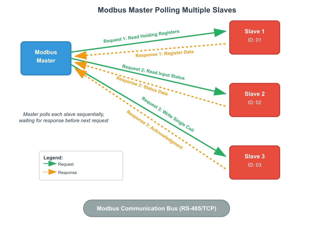
Master Request-Response Cycle
A typical Modbus transaction initiated by a Master follows these steps:
- Frame Construction: The Master constructs a Modbus RTU request frame. This includes:
- The target Slave Address (1-247).
- The desired Function Code (e.g.,
0x03for Read Holding Registers). - Data relevant to the function code (e.g., starting register address and number of registers to read).
- A calculated CRC-16 for error checking.
- Transmission: The Master transmits the frame over the serial line (e.g., RS-485).
- Waiting for Response: The Master then waits for a response from the Slave. It starts a timeout timer.
- Response Reception & Validation:
- If a response is received, the Master checks:
- The Slave Address in the response matches the queried Slave.
- The Function Code (it might indicate an exception if the MSB is set).
- The CRC-16 for data integrity.
- If all checks pass and it’s a normal response, the Master extracts the data.
- If it’s an exception response, the Master processes the exception code.
- If a response is received, the Master checks:
- Timeout Handling: If no response is received before the timeout timer expires, the Master assumes the Slave is unavailable or there was a communication failure for that transaction. It may then retry the request or move on to the next Slave/task.
Key Master Operations
A Modbus Master needs to implement logic for various operations:
- Reading Coils (Function Code
0x01): Requesting the status of one or more discrete output bits from a Slave. - Reading Discrete Inputs (Function Code
0x02): Requesting the status of one or more discrete input bits from a Slave. - Reading Holding Registers (Function Code
0x03): Requesting the content of one or more 16-bit read/write registers from a Slave. This is very common for reading analog values, setpoints, or configuration data. - Reading Input Registers (Function Code
0x04): Requesting the content of one or more 16-bit read-only registers from a Slave, often used for analog sensor inputs. - Writing Single Coil (Function Code
0x05): Instructing a Slave to turn a single discrete output ON or OFF. - Writing Single Holding Register (Function Code
0x06): Instructing a Slave to set the value of a single 16-bit read/write register. - Writing Multiple Coils (Function Code
0x0F): Instructing a Slave to set the status of a sequence of discrete outputs. - Writing Multiple Holding Registers (Function Code
0x10): Instructing a Slave to set the values of a sequence of 16-bit read/write registers.
Using ESP-IDF freemodbus for Master Mode
The ESP-IDF includes a robust freemodbus component (also referred to as esp_modbus_master in the context of master-specific APIs) that simplifies the implementation of a Modbus Master. Key features relevant to Master implementation include:
- API for Initialization: Functions to initialize the Modbus communication stack, configure serial parameters, and set the operating mode to Master.
- API for Sending Requests: High-level functions that abstract the details of frame construction and CRC calculation for common Modbus function codes. For example,
mbc_master_send_request()or more specific functions likembc_master_read_holding_registers(). (Note: API names might vary slightly based on the exact ESP-IDF version and abstraction level used; always refer to the latestesp_modbus.hand related headers). - Callback Mechanism (or Polling for Response): The library often provides mechanisms to notify the application when a response is received or a timeout occurs. This might involve callback functions or functions to poll the status of a sent request.
- Parameter Configuration: Through
menuconfig, you can set default serial port parameters, timing, and other Modbus-related settings.
What is a “Parameter Descriptor”?
When using the esp_modbus_master API, you’ll often encounter the concept of a “parameter descriptor” or mb_parameter_descriptor_t. This is a structure used to define the characteristics of the data you want to read from or write to a slave. It typically includes:
| Field Name | Description | Example Value |
|---|---|---|
| cid | Characteristic ID. A unique number (0-255) you assign to identify this specific data request within your master application. | 0 or CID_TEMPERATURE_SENSOR |
| param_key | A human-readable string key for the parameter. Useful for logging or displaying data. | “Temperature” |
| param_units | A human-readable string for the data’s units. | “C” or “%” |
| mb_slave_addr | The unique Modbus address (1-247) of the slave device you want to communicate with for this parameter. | 1 |
| mb_param_type | The type of Modbus register to access on the slave. | MB_PARAM_HOLDING (Holding Register) |
| mb_reg_start | The starting address of the register(s) within the slave. This is the 0-based protocol address (e.g., 0 for register 40001). | 100 |
| mb_size | The number of items (registers or coils) to read or write. For a 16-bit register, reading 2 registers means a size of 2. | 2 |
| param_opts | A nested structure defining how to interpret the raw data (type, size in bytes, endianness, scaling factor, min/max values). | {.type=PARAM_TYPE_U16, .size=2, …} |
| access | Defines the access rights for this parameter from the master’s perspective. | PROP_FLAG_READ | PROP_FLAG_WRITE |
cid: A unique identifier for this parameter or communication request (Characteristic ID).param_key: A user-friendly name or string key for the parameter.param_units: Units of the parameter (e.g., “C”, “V”, “%”).mb_slave_addr: The Modbus slave address for this parameter.mb_param_type: The Modbus register type (e.g.,MB_PARAM_HOLDING,MB_PARAM_INPUT,MB_PARAM_COIL,MB_PARAM_DISCRETE).mb_reg_start: The starting register address within the slave.mb_size: The number of registers or bits to read/write. For registers, this is often in bytes.param_offset: An internal offset used by the Modbus stack.param_opts: Parameter options for scaling, data type (e.g., float, uint16), and range.
This structure allows the Modbus master component to manage and interpret data from various slaves in a standardized way.
Practical Examples with ESP32
This section demonstrates how to set up and use an ESP32 as a Modbus RTU Master. We will use the esp_modbus_master API provided by the freemodbus component in ESP-IDF.
1. Project Setup and Component Configuration
a. CMakeLists.txt in your main component:
Ensure your main/CMakeLists.txt (or your custom component’s CMakeLists.txt) includes freemodbus in its requirements.
# main/CMakeLists.txt
idf_component_register(SRCS "app_main.c"
                    INCLUDE_DIRS "."
                    REQUIRES esp_event esp_log freemodbus)
b. sdkconfig.defaults (Optional but Recommended):
To ensure consistent build configurations, especially for UART pins, you can add default settings to an sdkconfig.defaults file in your project root.
# sdkconfig.defaults
CONFIG_FMB_COMM_MODE_RTU_EN=y
CONFIG_FMB_UART_PORT_NUM=1 # Example: UART1
CONFIG_FMB_UART_BAUD_RATE_9600=y # Example: 9600 baud
CONFIG_FMB_UART_PARITY_NONE=y  # Example: No parity
CONFIG_FMB_UART_TXD_PIN=17     # Example: GPIO17 for TX
CONFIG_FMB_UART_RXD_PIN=16     # Example: GPIO16 for RX
CONFIG_FMB_UART_RTS_PIN=18     # Example: GPIO18 for RS485 DE/RE
# CONFIG_MB_CONTROLLER_SLAVE_ID_SUPPORT is not needed for master
CONFIG_MB_CONTROLLER_MASTER_MAX_CIDS=10 # Max characteristic descriptors
CONFIG_MB_CONTROLLER_MASTER_TIMEOUT_MS_DEFAULT=1000 # Default timeout
After adding/modifying sdkconfig.defaults, run idf.py reconfigure.
c. menuconfig Configuration:
Alternatively, or for finer adjustments, use idf.py menuconfig:
- Navigate to
Component config—>Modbus configuration (FreeModbus)—>- Ensure
Modbus communication mode (RTU)is selected orModbus Serial support enableis checked. - Set
UART port number for Modbus communication. - Set
UART baud rate for Modbus communication. - Set
UART parity for Modbus communication. - Configure
UART TXD pin for Modbus communication. - Configure
UART RXD pin for Modbus communication. - Configure
UART RTS pin for Modbus communication(this is crucial for RS485 DE/RE control). - Set
Modbus controller master characteristic numbers(max CIDs). - Set
Modbus controller master response timeout (ms).
- Ensure
Tip: The
UART RTS pinis used by the ESP-IDF UART driver inUART_MODE_RS485_HALF_DUPLEXto automatically control the DE/RE pins of your RS-485 transceiver. Ensure this pin is correctly wired.
2. Hardware Setup
This is the same as described in Chapter 176:
- ESP32 development board.
- RS-485 transceiver module (e.g., MAX485).
- ESP32 TX -> Transceiver DI
- ESP32 RX -> Transceiver RO
- ESP32 RTS pin (as configured in
menuconfig) -> Transceiver DE/RE (ensure DE and RE are appropriately connected, often DE and /RE are tied together or RE is tied to GND if /RE). - Connect A/B lines of the transceiver to the RS-485 bus, along with your Modbus Slave device(s).
- Ensure proper bus termination (e.g., 120 Ohm resistors at both ends of the bus).
3. Modbus Master Implementation (app_main.c)
%%{ init: { 'theme': 'base', 'themeVariables': { 'fontFamily': 'Open Sans' } } }%%
graph TD
    A(Start Initialization) --> B("<b>mbc_master_init()</b><br>Initialize Master controller interface<br>Get master_handler");
    B --> C("<b>mbc_master_setup()</b><br>Configure communication parameters<br><i>(Port, Mode, Baud, Parity)</i>");
    C --> D("<b>mbc_master_set_descriptor()</b><br>Register characteristic definitions<br><i>(param_descriptors array)</i>");
    D --> E("<b>mbc_master_start()</b><br>Start the Modbus stack<br>This also configures and installs the UART driver");
    E --> F(Initialization Complete<br>Ready to Poll Slaves);

    classDef primary fill:#EDE9FE,stroke:#5B21B6,stroke-width:2px,color:#5B21B6;
    classDef success fill:#D1FAE5,stroke:#059669,stroke-width:2px,color:#065F46;
    classDef process fill:#DBEAFE,stroke:#2563EB,stroke-width:1px,color:#1E40AF;

    class A primary;
    class F success;
    class B,C,D,E process;
The following example demonstrates initializing the Modbus master, defining a characteristic to read, and periodically sending a request to read holding registers from a slave.
#include <stdio.h>
#include "freertos/FreeRTOS.h"
#include "freertos/task.h"
#include "esp_log.h"
#include "esp_system.h"
#include "esp_event.h"

// Modbus includes
#include "esp_modbus_common.h"
#include "esp_modbus_master.h"

static const char *TAG = "MODBUS_MASTER_APP";

// Define Modbus communication parameters (these will be overridden by menuconfig if set there)
#define MB_PORT_NUM     CONFIG_FMB_UART_PORT_NUM    // UART port number from menuconfig
#define MB_SLAVE_ADDR   (1)                         // Address of the slave device to query
#define MB_DEVICE_SPEED CONFIG_FMB_UART_BAUD_RATE // Baud rate from menuconfig

// Define the Modbus parameters we want to read (example: 2 holding registers starting at address 0)
#define CID_HOLDING_REG_TEST    0 // Unique characteristic ID
#define REG_COUNT_HOLDING_TEST  2 // Number of registers to read

// Structure to hold the Modbus parameter description
// This defines what data to read from the slave
const mb_parameter_descriptor_t param_descriptors[] = {
    {
        // Characteristic ID
        CID_HOLDING_REG_TEST,
        // Parameter name (user-defined)
        "Holding_Reg_Test",
        // Parameter units (user-defined)
        "counts",
        // Modbus slave address
        MB_SLAVE_ADDR,
        // Modbus register type
        MB_PARAM_HOLDING, // Read Holding Registers (FC03)
        // Starting register address in slave
        0, // Start address 0
        // Number of registers to read (size in words for registers)
        REG_COUNT_HOLDING_TEST,
        // Instance offset (usually 0 for simple cases)
        0,
        // Parameter options: data type, size, byte swap, etc.
        // Here, we expect two 16-bit unsigned integers.
        // Size is total bytes: REG_COUNT_HOLDING_TEST * 2 bytes/register
        { .type = PARAM_TYPE_U16, .size = 2, .offset = 0, .endianness = PARAM_BIG_ENDIAN, .scale = 1.0, .min = 0, .max = 65535 },
        // Access options (read/write)
        PROP_FLAG_READ // This parameter is readable
    }
};

// Number of defined Modbus parameters
const uint16_t num_param_descriptors = (sizeof(param_descriptors) / sizeof(param_descriptors[0]));

// Modbus master initialization function
static esp_err_t master_init(void)
{
    // Initialize Modbus controller interface
    // esp_modbus_master_init(MB_PORT_SERIAL_MASTER, &master_handle) is deprecated
    // Use mbcontroller_init, mbcontroller_setup, mbcontroller_start
    mb_communication_info_t comm_info;
    comm_info.port = MB_PORT_NUM; // UART port
    comm_info.mode = MB_MODE_RTU; // Modbus RTU mode
    comm_info.baudrate = MB_DEVICE_SPEED; // Baud rate
    comm_info.parity = MB_PARITY_NONE; // Parity (adjust as per your slave device)

    void* master_handler = NULL; // Pointer to master context

    esp_err_t err = mbc_master_init(MB_PORT_SERIAL_MASTER, &master_handler);
    MB_RETURN_ON_FALSE((master_handler != NULL), ESP_ERR_INVALID_STATE, TAG,
                                "Modbus master init failed.");
    MB_RETURN_ON_FALSE((err == ESP_OK), err, TAG,
                                "Modbus master init failed, error code: 0x%x.", (int)err);

    err = mbc_master_setup((void*)master_handler, (void*)&comm_info);
    MB_RETURN_ON_FALSE((err == ESP_OK), err, TAG,
                                "Modbus master setup failed, error code: 0x%x.", (int)err);

    // Set Modbus controller slave addresses that will be used by master instance
    // This is not for setting the master's own address, but rather pre-allocating resources
    // for slaves it will communicate with. For this example, we only poll one slave.
    // The actual slave address is in the parameter descriptor.
    // uint8_t slave_addr_arr[] = {MB_SLAVE_ADDR};
    // err = mbc_master_set_slaves(master_handler, slave_addr_arr, 1);
    // MB_RETURN_ON_FALSE((err == ESP_OK), err, TAG,
    //                             "Modbus master set slaves failed, error code: 0x%x.", (int)err);
    // Note: mbc_master_set_slaves might not be strictly needed if slave addresses are defined in CIDs.

    // Initialize Modbus parameters for master
    // This registers the characteristics (param_descriptors) with the Modbus stack
    err = mbc_master_set_descriptor((void*)master_handler, param_descriptors, num_param_descriptors);
    MB_RETURN_ON_FALSE((err == ESP_OK), err, TAG,
                                "Modbus master set descriptor failed, error code: 0x%x.", (int)err);

    ESP_LOGI(TAG, "Modbus master stack initialized.");

    // Start Modbus controller stack
    err = mbc_master_start((void*)master_handler);
    MB_RETURN_ON_FALSE((err == ESP_OK), err, TAG,
                                "Modbus master stack start failed, error code: 0x%x.", (int)err);

    // The UART driver is automatically installed and configured by mbc_master_start()
    // using settings from menuconfig (or default if not set).
    // Specifically, it uses UART_MODE_RS485_HALF_DUPLEX with the configured RTS pin for DE/RE.
    ESP_LOGI(TAG, "Modbus master stack started.");
    return ESP_OK;
}

// Task to periodically send Modbus requests
static void master_poll_task(void *arg)
{
    esp_err_t err = ESP_OK;
    uint8_t data_buffer[16]; // Buffer to store received data (adjust size as needed)

    ESP_LOGI(TAG, "Modbus master polling task started.");

    while (1) {
        // Send request to read holding registers for CID_HOLDING_REG_TEST
        // The master_handler is implicitly used by mbc_master_get_cid_data
        // The request is sent to the slave address defined in the param_descriptor for CID_HOLDING_REG_TEST
        ESP_LOGI(TAG, "Reading Holding Registers (CID: %d) from Slave %d", CID_HOLDING_REG_TEST, MB_SLAVE_ADDR);

        // mbc_master_get_cid_data sends the request and waits for the response or timeout
        // The slave address, function code, register address, and count are taken from the descriptor
        // associated with CID_HOLDING_REG_TEST.
        err = mbc_master_get_cid_data(param_descriptors[CID_HOLDING_REG_TEST].cid, data_buffer, NULL);

        if (err == ESP_OK) {
            // Data received successfully
            uint16_t reg_value1 = (data_buffer[0] << 8) | data_buffer[1];
            uint16_t reg_value2 = (data_buffer[2] << 8) | data_buffer[3];
            // Note: Data is typically Big Endian from Modbus.
            // The param_opts.endianness in descriptor can handle swapping if needed by stack,
            // but here we assume raw bytes are in data_buffer as received.
            // If PARAM_BIG_ENDIAN is used in descriptor and type is U16, the stack might provide it correctly.
            // Let's assume data_buffer contains raw bytes as per Modbus standard (Big Endian).

            ESP_LOGI(TAG, "Successfully read %d holding registers from slave %d.", REG_COUNT_HOLDING_TEST, MB_SLAVE_ADDR);
            ESP_LOGI(TAG, "Register 0 Value: %u (0x%04X)", reg_value1, reg_value1);
            ESP_LOGI(TAG, "Register 1 Value: %u (0x%04X)", reg_value2, reg_value2);

        } else {
            // Error occurred
            ESP_LOGE(TAG, "Failed to read holding registers from slave %d, CID %d. Error: %s (0x%x)",
                     MB_SLAVE_ADDR, CID_HOLDING_REG_TEST, esp_err_to_name(err), err);
            // Common errors:
            // ESP_ERR_TIMEOUT: Slave did not respond
            // ESP_ERR_INVALID_RESPONSE: CRC error or malformed response
            // ESP_ERR_NOT_SUPPORTED: Slave returned an exception code
            // Check the specific exception code if err is ESP_ERR_NOT_SUPPORTED
            // by calling mbc_master_get_exception_code() if needed, though
            // esp_modbus_master usually translates common exceptions to ESP_ERR_*.
        }

        // Wait before sending the next request
        vTaskDelay(pdMS_TO_TICKS(5000)); // Poll every 5 seconds
    }
}


void app_main(void)
{
    ESP_LOGI(TAG, "Initializing ESP32 Modbus RTU Master...");

    // Initialize NVS needed by esp_event_loop
    esp_err_t ret = nvs_flash_init();
    if (ret == ESP_ERR_NVS_NO_FREE_PAGES || ret == ESP_ERR_NVS_NEW_VERSION_FOUND) {
      ESP_ERROR_CHECK(nvs_flash_erase());
      ret = nvs_flash_init();
    }
    ESP_ERROR_CHECK(ret);

    // Initialize the event loop (needed for some Modbus operations or other components)
    ESP_ERROR_CHECK(esp_event_loop_create_default());

    // Initialize Modbus master
    ESP_ERROR_CHECK(master_init());

    // Create a task to poll slave devices
    xTaskCreate(master_poll_task, "modbus_master_poll", 4096, NULL, 5, NULL);

    ESP_LOGI(TAG, "Modbus Master Application Initialized.");
}
Important Notes on the Code:
- Error Handling: The
MB_RETURN_ON_FALSEmacro (fromesp_modbus_common.h) is used for concise error checking during initialization. Robust error handling in the polling loop is crucial.- Parameter Descriptors (
param_descriptors): This array defines what data you want to access on the slave. Each entry specifies the slave ID, register type, start address, quantity, and how the data should be interpreted (type, size, endianness).mbc_master_get_cid_data(): This is a key function. It uses the information from the parameter descriptor (identified bycid) to construct and send the appropriate Modbus request. It then waits for the response or a timeout. The received data is placed into thedata_buffer.- Data Interpretation: The raw data received from the slave is typically Big Endian. You need to correctly interpret it based on the data type (e.g., U16, S16, U32, float). The
param_optsin the descriptor can help the Modbus stack with some of this, but you often handle byte ordering and type conversion in your application code after receiving the raw bytes.- Task-Based Polling: Modbus polling is typically done in a dedicated FreeRTOS task to avoid blocking other operations.
- Timeout Configuration: The master response timeout can be configured via
menuconfig(CONFIG_MB_CONTROLLER_MASTER_TIMEOUT_MS_DEFAULT) or programmatically if the API supports it.
4. Build, Flash, and Observe
a. Build the Project:
idf.py build
b. Flash to ESP32:
Connect your ESP32, then:
idf.py -p /dev/ttyUSB0 flash monitor
(Replace /dev/ttyUSB0 with your ESP32’s serial port).
c. Observation:
%%{ init: { 'theme': 'base', 'themeVariables': { 'fontFamily': 'Open Sans' } } }%%
graph TD
    A(Start Task) --> B("Enter 'while(1)' loop");
    B --> C("Call <b>mbc_master_get_cid_data()</b><br>to poll a slave for a specific CID");
    C --> D{"Request Successful?<br>(err == ESP_OK)"};
    D -- Yes --> E("Process received data<br><i>(e.g., byte swap, type cast)</i>");
    E --> F(Log or use the data);
    F --> G("<b>vTaskDelay()</b><br>Wait for next polling interval");
    G --> B;

    D -- No --> H("Log the specific error<br><i>(e.g., Timeout, Invalid Response)</i>");
    H --> G;

    classDef primary fill:#EDE9FE,stroke:#5B21B6,stroke-width:2px,color:#5B21B6;
    classDef success fill:#D1FAE5,stroke:#059669,stroke-width:2px,color:#065F46;
    classDef decision fill:#FEF3C7,stroke:#D97706,stroke-width:1px,color:#92400E;
    classDef process fill:#DBEAFE,stroke:#2563EB,stroke-width:1px,color:#1E40AF;
    classDef validation fill:#FEE2E2,stroke:#DC2626,stroke-width:1px,color:#991B1B;

    class A primary;
    class D decision;
    class E,F,B,C,G process;
    class H validation;
To test this Modbus Master, you need a Modbus RTU Slave device or simulator:
- Slave Device: A physical Modbus slave (e.g., a sensor, PLC, another ESP32 programmed as a slave) connected to the same RS-485 bus. Ensure its Slave ID is
1(orMB_SLAVE_ADDR), and it has at least two holding registers starting at address0. - Modbus Slave Simulator Software: Many free Modbus slave simulators are available for PC (e.g., Modbus Slave, Simply Modbus). Connect your PC to the RS-485 bus using a USB-to-RS485 adapter. Configure the simulator with Slave ID
1and define some holding registers at address0.
Expected Output in ESP32 Monitor:
If the Master successfully communicates with the Slave, you should see log messages like:
I (MODBUS_MASTER_APP): Reading Holding Registers (CID: 0) from Slave 1
I (MODBUS_MASTER_APP): Successfully read 2 holding registers from slave 1.
I (MODBUS_MASTER_APP): Register 0 Value: 12345 (0x3039)
I (MODBUS_MASTER_APP): Register 1 Value: 54321 (0xD431)
(The actual register values will depend on what the slave provides.)
If there’s an error (e.g., slave not connected, wrong ID, timeout):
I (MODBUS_MASTER_APP): Reading Holding Registers (CID: 0) from Slave 1
E (MODBUS_MASTER_APP): Failed to read holding registers from slave 1, CID 0. Error: ESP_ERR_TIMEOUT (0x107)
Variant Notes
The Modbus RTU Master implementation using esp_modbus_master is generally consistent across ESP32 variants.
- ESP32, ESP32-S2, ESP32-S3, ESP32-C3, ESP32-C6, ESP32-H2:
- All these variants possess UART peripherals suitable for Modbus RTU. The core
esp_modbus_masterAPI and its underlyingfreemodbuscomponent will work similarly. - UART Pin Selection: The primary difference will be the available GPIOs for UART TXD, RXD, and RTS (for DE/RE control). Always verify pin compatibility with your specific ESP32 module/board and configure them correctly in
menuconfigor yoursdkconfig.defaults. - Number of UARTs: All variants have at least two UART controllers, allowing one to be dedicated to Modbus while others might be used for logging or other communication.
- RS-485 Transceiver: An external RS-485 transceiver is always required, as detailed in the hardware setup.
- Performance: All listed variants have ample processing power to act as efficient Modbus Masters, even while handling other tasks like Wi-Fi, Bluetooth, or complex application logic. The performance impact of Modbus communication is generally low.
- All these variants possess UART peripherals suitable for Modbus RTU. The core
- Specific Considerations:
- ESP32-S2/S3 with USB-OTG: While they have USB, for Modbus RTU, the native UARTs are the standard choice. Using USB for Modbus RTU would typically involve a USB host stack and a USB-to-RS485 converter, adding complexity not usually necessary.
- ESP32-C6/H2 with 802.15.4: These chips can act as gateways, where the ESP32 Master polls Modbus RTU slaves and then relays this data over Thread or Zigbee. The Modbus RTU Master part remains the same.
The esp_modbus_master component abstracts away many low-level hardware differences, providing a consistent API experience. The main practical step is ensuring correct UART peripheral and pin configuration for your chosen variant.
Common Mistakes & Troubleshooting Tips
| Mistake / Issue | Symptom(s) | Troubleshooting / Solution |
|---|---|---|
| Incorrect RTS Pin Config | Master gets timeout errors, or receives its own transmissions back, causing invalid response errors. Collisions on the bus. |
1. Ensure CONFIG_FMB_UART_RTS_PIN in menuconfig is set to the GPIO connected to the transceiver’s DE/RE pins. 2. Verify the ESP-IDF driver is managing the pin by ensuring UART_MODE_RS485_HALF_DUPLEX is used (done automatically by mbc_master_start()). |
| Slave Timeout (ESP_ERR_TIMEOUT) | Master consistently fails to get a response from a slave. | Check the fundamentals: – Is the slave powered on? – Does the Slave ID in your param_descriptor match the actual slave’s ID? – Are serial parameters (baud, parity) identical? – Is the A/B wiring correct? – Is bus termination correct (120 Ohm at ends only)? |
| Incorrect Parameter Descriptor | Slave returns an exception (ESP_ERR_NOT_SUPPORTED) or you read garbage data. |
Carefully check the slave’s documentation. Ensure your mb_parameter_descriptor_t has the correct: – mb_param_type (e.g., HOLDING vs INPUT) – mb_reg_start (must be the 0-based address) – mb_size (number of registers/coils) |
| Invalid Response (ESP_ERR_INVALID_RESPONSE) | The master receives a frame, but the CRC is wrong or the length/slave ID is unexpected. | This often points to electrical noise or data corruption. – Use shielded, twisted-pair cable for RS-485. – Keep communication lines away from power lines. – Check for proper bus termination. – A faulty slave device could also be the cause. |
| Data Misinterpretation | You receive data but the values make no sense (e.g., huge numbers for temperature). |
1. Endianness: Modbus is big-endian. Ensure you are combining bytes correctly: (msb << 8) | lsb. 2. Data Type: Is the value a U16, S16, U32, or float? Handle it accordingly. 3. Scaling: The slave may provide an integer that needs to be scaled (e.g., value 256 means 25.6 C). Check the slave’s manual for scaling factors. |
Exercises
- Write to a Single Coil:
- Modify the provided example. Add a new
mb_parameter_descriptor_tto control a single coil (e.g., at address 0) on slaveMB_SLAVE_ADDR. - In the
master_poll_task, alternate between turning this coil ON (0xFF00) and OFF (0x0000) usingmbc_master_set_cid_data(). - Test with a Modbus slave simulator or a device that has a configurable coil.
- Modify the provided example. Add a new
- Read Discrete Inputs:
- Define a new parameter descriptor to read 4 Discrete Inputs starting at address 0 from the slave.
- Use
mbc_master_get_cid_data()to read these inputs and log their status. - Configure your slave simulator to provide some discrete input values.
- Handle Multiple Slaves:
- Assume you have two slave devices on the bus with IDs 1 and 2.
- Create parameter descriptors for reading one holding register from Slave 1 (address 0) and one holding register from Slave 2 (address 0).
- Modify
master_poll_taskto read from both slaves sequentially.
- Error Code Analysis:
- Intentionally configure your master to request a holding register address that you know does not exist on your Modbus slave (e.g., address 9999).
- Observe the error code returned by
mbc_master_get_cid_data(). How does the ESP-IDF Modbus master component report a Modbus “Illegal Data Address” exception? Log the specific error.
- Dynamic Data Request:
- Create a simple command interface via UART console (using
stdinor a simple command parser) that allows the user to specify:- Slave ID
- Function Code (e.g., 3 for Read Holding, 6 for Write Single Register)
- Starting Register Address
- Number of Registers (for reads) or Value (for writes)
- Upon receiving a command, dynamically (if possible with current API, or by re-configuring a general-purpose descriptor) send the Modbus request and display the result. This is more advanced and might require deeper interaction with the Modbus API or managing descriptors more flexibly. Focus on sending a request for reading a holding register based on user input for slave ID, start address, and count.
- Create a simple command interface via UART console (using
Summary
- The Modbus Master initiates all communication by sending requests to Slaves and processing their responses or handling timeouts.
- ESP-IDF’s
freemodbuscomponent (esp_modbus_master) provides a comprehensive API for Modbus RTU Master implementation on ESP32. - Configuration is done via
menuconfig(for UART, pins, default timeouts) and by definingmb_parameter_descriptor_tstructures in code to describe the data to be accessed. - Key functions include
mbc_master_init(),mbc_master_setup(),mbc_master_set_descriptor(),mbc_master_start(), andmbc_master_get_cid_data()/mbc_master_set_cid_data(). - An external RS-485 transceiver is necessary, and correct wiring of TX, RX, and RTS (for DE/RE control) is critical.
- The ESP-IDF UART driver’s
UART_MODE_RS485_HALF_DUPLEXfeature simplifies RS-485 direction control. - Robust error handling, especially for timeouts and slave exceptions, is essential for reliable Master operation.
- All ESP32 variants are well-suited for Modbus RTU Master applications, with primary considerations being UART peripheral and pin selection.
Further Reading
- ESP-IDF Modbus Documentation:
- Official ESP-IDF Programming Guide: Look for sections on “Modbus Controller” or
esp_modbus_master. (Search on https://docs.espressif.com/projects/esp-idf/) - Header files in ESP-IDF:
esp_modbus_common.h,esp_modbus_master.h. These are the ultimate source for API details.
- Official ESP-IDF Programming Guide: Look for sections on “Modbus Controller” or
- Modbus Organization:
- Modbus Application Protocol Specification: http://www.modbus.org/specs.php
- RS-485 Standard:
- Understanding RS-485 networking principles (termination, biasing, wiring) is beneficial for troubleshooting.
