
Chapter 163: MCPWM for Brushless DC Motor Control
Chapter Objectives
By the end of this chapter, you will be able to:
- Understand the fundamental operating principles of Brushless DC (BLDC) motors.
- Describe the construction of a typical 3-phase BLDC motor.
- Explain the concept of electronic commutation and its necessity for BLDC motors.
- Detail the 6-step (trapezoidal) commutation method using Hall effect sensors.
- Configure MCPWM capture inputs or GPIO interrupts to read Hall sensor signals.
- Implement a commutation sequence based on Hall sensor feedback.
- Configure the ESP32’s MCPWM peripheral to drive a 3-phase inverter bridge for BLDC motors.
- Generate complementary PWM signals with dead-time for each phase of the BLDC motor.
- Implement basic open-loop speed control for a BLDC motor.
- Understand considerations for direction control.
- Identify differences in MCPWM capabilities relevant to BLDC control across ESP32 variants.
Introduction
In Chapter 162, we explored the fundamentals of the ESP32‘s Motor Control PWM (MCPWM) peripheral, a versatile tool for generating sophisticated PWM waveforms. Now, we will apply that knowledge to one of the most common and important applications in modern motion control: driving Brushless DC (BLDC) motors.
BLDC motors are ubiquitous, found in everything from computer hard drives and cooling fans to drones, electric vehicles, robotics, and industrial automation. Their popularity stems from their high efficiency, excellent torque-to-weight ratio, long lifespan (due to the absence of brushes), and relatively low maintenance requirements. However, unlike their brushed counterparts, BLDC motors cannot be driven by simply applying a DC voltage. They require electronic commutation – a process of switching the current in the motor windings in a specific sequence to create continuous rotation.
%%{init: {'theme': 'base', 'themeVariables': { 'fontFamily': 'Open Sans'}}}%%
graph TD
    subgraph "Control Unit"
        ESP32[ESP32 Microcontroller]
    end

    subgraph "Power Electronics"
        Driver["3-Phase Inverter Bridge<br>(e.g., L6234, DRV830x)"]
    end

    subgraph "Actuator"
        Motor[BLDC Motor]
        Hall[Hall Effect<br>Sensors]
    end

    subgraph "Power Source"
        PSU["Power Supply<br>(e.g., 12V DC)"]
    end

    ESP32 -- "<b>6 PWM Signals</b><br>(U_H, U_L, V_H, V_L, W_H, W_L)<br><i>via MCPWM</i>" --> Driver;
    Hall -- "<b>3 Hall Signals</b><br>(Rotor Position Feedback)<br><i>to GPIO/MCPWM Capture</i>" --> ESP32;

    Driver -- "3-Phase<br>U, V, W" --> Motor;
    Motor -.-> Hall;

    PSU -- "+Vbus & GND" --> Driver;

    %% Styling
    classDef primary fill:#EDE9FE,stroke:#5B21B6,stroke-width:2px,color:#5B21B6;
    classDef process fill:#DBEAFE,stroke:#2563EB,stroke-width:1px,color:#1E40AF;
    classDef check fill:#FEE2E2,stroke:#DC2626,stroke-width:1px,color:#991B1B;
    classDef success fill:#D1FAE5,stroke:#059669,stroke-width:2px,color:#065F46;

    class ESP32 primary;
    class Driver,Motor,Hall process;
    class PSU check;
This chapter will guide you through the theory of BLDC motor operation and demonstrate how to use the ESP32’s MCPWM peripheral, in conjunction with Hall effect sensors for rotor position feedback, to implement 6-step trapezoidal commutation for controlling a 3-phase BLDC motor.
Theory
BLDC Motor Fundamentals
Construction
A BLDC motor consists of two main parts:
- Stator: The stationary part of the motor. It comprises a set of windings (coils) arranged around a laminated steel core. For a typical 3-phase BLDC motor, there are three sets of windings (often labeled U, V, W or A, B, C), which are usually connected in either a Star (Y) or Delta (Δ) configuration.
- Rotor: The rotating part of the motor. It contains permanent magnets. The number of magnetic poles on the rotor can vary (e.g., 2-pole, 4-pole, 8-pole, etc.).

Unlike brushed DC motors, BLDC motors do not have mechanical brushes or a commutator to switch the current in the windings. Instead, this process, known as electronic commutation, is handled by an external electronic controller (often a microcontroller like the ESP32 driving a 3-phase inverter).
Working Principle
The fundamental principle is based on the Lorentz force: when a current-carrying conductor is placed in a magnetic field, it experiences a force. In a BLDC motor:
- Current is passed through specific stator windings, creating an electromagnetic field.
- This electromagnetic field interacts with the permanent magnets on the rotor.
- The interaction creates a torque, causing the rotor to try and align with the stator’s magnetic field.
- To maintain continuous rotation, the current in the stator windings must be switched (commutated) in a sequence that keeps the stator’s magnetic field “ahead” of the rotor’s magnetic field, effectively “pulling” the rotor along.
The timing of this switching is critical and must be synchronized with the rotor’s position.
Electronic Commutation
Why is it Needed?
Since there are no brushes, an external system must determine the rotor’s position and energize the appropriate stator windings at the correct time. This is the role of the electronic commutation controller.
Hall Effect Sensors
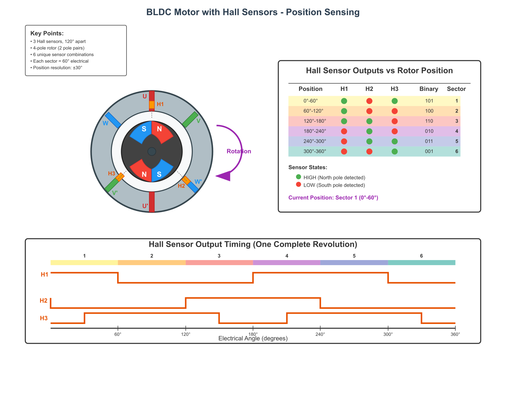
One of the most common methods for determining rotor position in BLDC motors is by using Hall effect sensors. These sensors detect the magnetic field of the rotor magnets. Typically, three Hall sensors are embedded in the stator, spaced 60 or 120 electrical degrees apart.
- As the rotor turns, the magnets pass by the Hall sensors, causing them to output a digital signal (high or low).
- The combination of the three Hall sensor outputs forms a 3-bit code (e.g., 101, 001, etc.), which uniquely identifies the rotor’s position within one of six 60-electrical-degree sectors.
- An electrical degree is different from a mechanical degree. One full mechanical rotation corresponds to
(Number of Rotor Pole Pairs) * 360electrical degrees. For a 4-pole motor (2 pole pairs), one mechanical rotation is 720 electrical degrees.
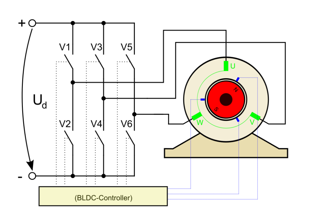
3-Phase Inverter Bridge
To drive a 3-phase BLDC motor, a 3-phase inverter bridge is used. This bridge typically consists of six power switching elements (usually MOSFETs or IGBTs), arranged in three half-bridge pairs (one pair for each motor phase U, V, W).
- Each half-bridge has a high-side switch (connected to the positive DC bus) and a low-side switch (connected to ground or the negative DC bus).
- By controlling these six switches, current can be directed through any two of the three motor phases in either direction.
6-Step Trapezoidal Commutation
This is a common and relatively simple method for BLDC motor control. It’s called “6-step” because there are six distinct states of Hall sensor inputs (and thus six commutation steps) for every electrical cycle. It’s called “trapezoidal” because the back-EMF (ElectroMotive Force) generated by the motor when it rotates has a trapezoidal shape, and this method aims to align the applied current with the flat portions of the back-EMF waveform for optimal torque.
Commutation Sequence:
In each of the six steps:
- One phase is connected to the positive DC bus (high-side switch ON, low-side OFF).
- Another phase is connected to the negative DC bus (low-side switch ON, high-side OFF).
- The third phase is left floating (both high-side and low-side switches OFF) or actively driven depending on the specific control scheme (e.g., PWM on high-side, complementary PWM on low-side).
The speed of the motor is typically controlled by applying PWM to the active high-side switch (or sometimes both high and low-side switches in a complementary manner) in the currently energized pair.
Commutation Table:
The core of 6-step commutation is a table that maps the Hall sensor states to the required states of the six inverter switches. The exact table depends on the motor’s winding configuration, Hall sensor placement (60 or 120 electrical degrees), and desired direction of rotation.
Here’s an example commutation table for a typical BLDC motor (assuming Hall sensors give a sequence like 101, 100, 110, 010, 011, 001 for one direction):
| Sector | Hall Sensor State | Phase State | Energized Phases | ||||
|---|---|---|---|---|---|---|---|
| H3 (W) | H2 (V) | H1 (U) | Phase U | Phase V | Phase W | ||
| 1 | 1 | 0 | 1 | + (PWM) | – (GND) | OFF | U → V |
| 2 | 1 | 0 | 0 | + (PWM) | OFF | – (GND) | U → W |
| 3 | 1 | 1 | 0 | OFF | + (PWM) | – (GND) | V → W |
| 4 | 0 | 1 | 0 | – (GND) | + (PWM) | OFF | V → U |
| 5 | 0 | 1 | 1 | – (GND) | OFF | + (PWM) | W → U |
| 6 | 0 | 0 | 1 | OFF | – (GND) | + (PWM) | W → V |
- + (PWM): Phase connected to Vbus, typically via a PWM-controlled high-side MOSFET.
- – (GND): Phase connected to Ground, typically via an ON low-side MOSFET.
- OFF: Phase is floating (both high-side and low-side MOSFETs are OFF).

MCPWM Configuration for 6-Step Commutation:
To implement this with MCPWM:
- Timers: Typically, one MCPWM timer is sufficient. Its frequency will determine the PWM frequency applied to the motor phases.
MCPWM_TIMER_COUNT_MODE_UP_DOWNis often preferred for symmetric PWM. - Operators: Three MCPWM operators are needed, one for each motor phase (U, V, W). Each operator will be connected to the common timer.
- Comparators: Each operator will have one comparator. The
compare_valueof this comparator will determine the duty cycle of the PWM signal, thus controlling motor speed. - Generators: Each operator will have two generators (e.g., U_H for high-side, U_L for low-side). These will be configured for complementary output with dead-time to drive one leg of the 3-phase inverter.
mcpwm_generator_config_tfor U_H, U_L, V_H, V_L, W_H, W_L.mcpwm_operator_apply_deadtime()for each operator.
- Dynamic Control (Commutation Logic):
- When a Hall sensor state changes, the commutation logic needs to:
- Identify the new sector.
- Consult the commutation table.
- Reconfigure the MCPWM generators for each phase accordingly. This involves:
- For the phase to be PWM’d high: Set its high-side generator (e.g., U_H) to produce PWM based on the comparator, and its low-side generator (U_L) to be complementary (i.e., OFF when U_H is ON, and ON during dead-time if configured that way, but generally OFF during the main PWM pulse).
- For the phase to be connected to GND: Force its high-side generator OFF and its low-side generator ON (e.g., using
mcpwm_generator_set_force_level()). - For the floating phase: Force both its high-side and low-side generators OFF.
- The
mcpwm_generator_set_force_level(gen_handle, level, hold_mode)function is crucial here.level: The desired output level (0 or 1).hold_mode:MCPWM_GENERATOR_FORCE_LEVEL_LOW_IMMEDIATEorMCPWM_GENERATOR_FORCE_LEVEL_HIGH_IMMEDIATEto apply the force immediately. To release the force and return to normal PWM operation based on timer/compare events, you can set the level to -1 (or useMCPWM_GENERATOR_FORCE_LEVEL_NOT_FORCE).
- When a Hall sensor state changes, the commutation logic needs to:
%%{init: {'theme': 'base', 'themeVariables': { 'fontFamily': 'Open Sans'}}}%%
graph TD
    A[Start: Motor Idle] --> B{Hall Sensor<br>State Change?};
    B -- No --> B;
    B -- Yes (ISR Trigger) --> C(Read Hall Pins<br>H3, H2, H1);

    C --> D(Update <b>current_hall_state</b>);
    D --> E{Is State Valid?};

    E -- No --> F(Stop Motor<br>Force all phases OFF);
    F --> B;

    E -- Yes --> G(Lookup Commutation Table<br>for <b>current_hall_state</b>);

    subgraph "Apply New Step"
      direction LR
      G --> H(Release Force Levels<br>on all 6 Generators);
      H --> I(Set Duty Cycle Value<br>on all 3 Comparators);
      I --> J(<b>For PWM Phase:</b><br>Do nothing, let PWM run);
      J --> K(<b>For GND Phase:</b><br>Force High-Side OFF<br>Force Low-Side ON);
      K --> L(<b>For OFF Phase:</b><br>Force High-Side OFF<br>Force Low-Side OFF);
    end

    L --> B;

    %% Styling
    classDef primary fill:#EDE9FE,stroke:#5B21B6,stroke-width:2px,color:#5B21B6;
    classDef decision fill:#FEF3C7,stroke:#D97706,stroke-width:1px,color:#92400E;
    classDef process fill:#DBEAFE,stroke:#2563EB,stroke-width:1px,color:#1E40AF;
    classDef check fill:#FEE2E2,stroke:#DC2626,stroke-width:1px,color:#991B1B;

    class A,B primary;
    class C,D,G,H,I,J,K,L process;
    class E decision;
    class F check;
Speed and Direction Control
- Speed Control: Achieved by varying the duty cycle of the PWM signal applied to the active high-side MOSFET. A higher duty cycle means more average voltage to the motor, resulting in higher speed. This is done by changing the
compare_valueof the MCPWM comparators. - Direction Control: Achieved by reversing the commutation sequence or by swapping two of the motor phase connections (though reversing the sequence electronically is preferred). This means having two commutation tables, one for forward and one for reverse.
Sensorless BLDC Control (Brief Overview)
For applications where Hall sensors are not desirable (cost, space, reliability concerns), sensorless control techniques can be used. The most common method involves detecting the Back-EMF (BEMF) zero-crossings of the unenergized phase.
- When a BLDC motor rotates, its windings generate a voltage called Back-EMF.
- The BEMF of the unenergized phase can be monitored. Its zero-crossing point (relative to the motor’s neutral point or half the DC bus voltage) provides information about the rotor’s position.
- This method is more complex to implement, especially at low speeds or standstill where BEMF is weak or non-existent. It often requires sophisticated filtering and ADC measurements.
- This chapter focuses on Hall sensor-based control due to its relative simplicity and robustness for getting started.
Practical Examples
Prerequisites:
- An ESP32 development board.
- A 3-phase BLDC motor with Hall sensors.
- A 3-phase motor driver/inverter board (e.g., based on L6234, DRV830x series, or discrete MOSFETs with gate drivers). Ensure it’s compatible with your ESP32’s logic levels (3.3V) and your motor’s voltage/current requirements.
- Appropriate power supply for the motor and driver board.
Warning: Working with motors and motor drivers can involve significant currents and voltages. Always double-check your wiring before applying power. Start with a current-limited power supply if possible. Incorrect wiring or control logic can damage your ESP32, motor driver, or motor.
Common Setup for Examples:
#include <stdio.h>
#include "freertos/FreeRTOS.h"
#include "freertos/task.h"
#include "esp_log.h"
#include "driver/mcpwm_prelude.h"
#include "driver/gpio.h" // For Hall sensor GPIOs if not using MCPWM capture

static const char *TAG = "bldc_control";

// --- Define your motor and driver specific GPIOs here ---
// Example: MCPWM outputs for 3 phases (High-side and Low-side)
#define PHASE_U_H_GPIO  13 // Connect to U_High input of driver
#define PHASE_U_L_GPIO  12 // Connect to U_Low input of driver (if separate control, else MCPWM handles complementary)
#define PHASE_V_H_GPIO  14
#define PHASE_V_L_GPIO  27
#define PHASE_W_H_GPIO  26
#define PHASE_W_L_GPIO  25

// Example: Hall Sensor GPIOs
#define HALL_U_GPIO     32
#define HALL_V_GPIO     33
#define HALL_W_GPIO     35

// MCPWM Configuration (adjust as needed)
#define BLDC_MCPWM_TIMER_RESOLUTION_HZ 1000000 // 1MHz, 1us tick
#define BLDC_MCPWM_PERIOD_TICKS        100     // Results in 1MHz / (2*100) = 5kHz PWM for UP_DOWN count
                                               // Or 1MHz / 100 = 10kHz PWM for UP count
#define BLDC_MCPWM_GROUP_ID 0

// Dead time (in timer ticks, 1us per tick if resolution is 1MHz)
#define BLDC_DEAD_TIME_TICKS 2 // 2us dead time

// Global handles for MCPWM
mcpwm_timer_handle_t bldc_timer = NULL;
mcpwm_oper_handle_t oper_u = NULL, oper_v = NULL, oper_w = NULL;
mcpwm_cmpr_handle_t comp_u = NULL, comp_v = NULL, comp_w = NULL;
mcpwm_gen_handle_t gen_u_h = NULL, gen_u_l = NULL;
mcpwm_gen_handle_t gen_v_h = NULL, gen_v_l = NULL;
mcpwm_gen_handle_t gen_w_h = NULL, gen_w_l = NULL;

// Global variable for current duty cycle (0-100%)
volatile uint32_t current_duty_cycle_percent = 0;

// Hall sensor state
volatile uint8_t current_hall_state = 0; // 3-bit value: H_W | H_V | H_U
Example 1: Reading Hall Sensors and Determining Sector
This example shows how to read Hall sensor inputs using GPIO interrupts and update current_hall_state. Using MCPWM capture for Hall sensors is also possible (see Chapter 162, Example 4) and can be more precise for timing, but GPIO interrupts are often simpler for basic state detection.
// Shared queue for Hall sensor events (optional, for debouncing or complex logic)
// QueueHandle_t hall_event_queue;
// ISR handler for Hall sensor GPIOs
static void IRAM_ATTR hall_sensor_isr_handler(void *arg) {
// Simple read, no debouncing in this basic example
uint32_t hall_u_val = gpio_get_level(HALL_U_GPIO);
uint32_t hall_v_val = gpio_get_level(HALL_V_GPIO);
uint32_t hall_w_val = gpio_get_level(HALL_W_GPIO);
current_hall_state = (hall_w_val << 2) | (hall_v_val << 1) | hall_u_val;
// If using a queue to notify a task:
// xQueueSendFromISR(hall_event_queue, ¤t_hall_state, NULL);
}
void init_hall_sensors(void) {
ESP_LOGI(TAG, "Initializing Hall Sensors");
gpio_config_t io_conf = {
.intr_type = GPIO_INTR_ANYEDGE, // Trigger on any change
.mode = GPIO_MODE_INPUT,
.pin_bit_mask = (1ULL << HALL_U_GPIO) | (1ULL << HALL_V_GPIO) | (1ULL << HALL_W_GPIO),
.pull_down_en = 0,
.pull_up_en = 1, // Enable pull-ups, common for open-collector Hall sensors
};
gpio_config(&io_conf);
// Install GPIO ISR service if not already installed
gpio_install_isr_service(ESP_INTR_FLAG_LEVEL1); // Or other appropriate flags
// Hook ISR handlers
gpio_isr_handler_add(HALL_U_GPIO, hall_sensor_isr_handler, (void *)HALL_U_GPIO);
gpio_isr_handler_add(HALL_V_GPIO, hall_sensor_isr_handler, (void *)HALL_V_GPIO);
gpio_isr_handler_add(HALL_W_GPIO, hall_sensor_isr_handler, (void *)HALL_W_GPIO);
// Initial read
hall_sensor_isr_handler(NULL); // Call once to get initial state
ESP_LOGI(TAG, "Initial Hall State: %d", current_hall_state);
}
Note on MCPWM Capture for Hall Sensors:
If using MCPWM capture, you would configure three capture channels, one for each Hall sensor. The on_cap callback for each would update the corresponding bit in current_hall_state. This can be more robust against noise if the capture peripheral has filtering and can provide precise timing for speed calculation.
Example 2: MCPWM Setup for 3-Phase Bridge
This function initializes the MCPWM timer, operators, comparators, and generators for the three phases (U, V, W). It sets them up for complementary PWM with dead-time. The actual commutation logic will later use mcpwm_generator_set_force_level or adjust actions.
void init_bldc_mcpwm(void) {
    ESP_LOGI(TAG, "Create MCPWM timer");
    mcpwm_timer_config_t timer_config = {
        .group_id = BLDC_MCPWM_GROUP_ID,
        .clk_src = MCPWM_TIMER_CLK_SRC_DEFAULT,
        .resolution_hz = BLDC_MCPWM_TIMER_RESOLUTION_HZ,
        .period_ticks = BLDC_MCPWM_PERIOD_TICKS,
        .count_mode = MCPWM_TIMER_COUNT_MODE_UP_DOWN, // Symmetric PWM
    };
    ESP_ERROR_CHECK(mcpwm_new_timer(&timer_config, &bldc_timer));

    // Operator and Comparator configuration is similar for U, V, W
    // Phase U
    ESP_LOGI(TAG, "Create operator U");
    mcpwm_operator_config_t oper_u_config = {.group_id = BLDC_MCPWM_GROUP_ID};
    ESP_ERROR_CHECK(mcpwm_new_operator(&oper_u_config, &oper_u));
    ESP_ERROR_CHECK(mcpwm_operator_connect_timer(oper_u, bldc_timer));

    ESP_LOGI(TAG, "Create comparator U");
    mcpwm_comparator_config_t comp_u_config = {.flags.update_cmp_on_tez = true};
    ESP_ERROR_CHECK(mcpwm_new_comparator(oper_u, &comp_u_config, &comp_u));
    // Initial duty cycle (e.g., 0%)
    ESP_ERROR_CHECK(mcpwm_comparator_set_compare_value(comp_u, 0));

    ESP_LOGI(TAG, "Create generator U_H and U_L");
    mcpwm_generator_config_t gen_uh_config = {.gen_gpio_num = PHASE_U_H_GPIO};
    ESP_ERROR_CHECK(mcpwm_new_generator(oper_u, &gen_uh_config, &gen_u_h));
    mcpwm_generator_config_t gen_ul_config = {.gen_gpio_num = PHASE_U_L_GPIO}; // Or -1 if driver has internal deadtime and takes single PWM + DIR
    ESP_ERROR_CHECK(mcpwm_new_generator(oper_u, &gen_ul_config, &gen_u_l));

    // Set default actions for U_H (active high PWM)
    // These actions will be overridden by commutation logic using set_force_level
    // or by dynamically changing actions. For now, let's set a standard PWM pattern.
    ESP_ERROR_CHECK(mcpwm_generator_set_actions_on_timer_event(gen_u_h,
        MCPWM_GEN_TIMER_EVENT_ACTION(MCPWM_TIMER_EVENT_EMPTY, MCPWM_GEN_ACTION_HIGH, 0), // For UP_DOWN, TEP is also a common choice for one edge
        MCPWM_GEN_TIMER_EVENT_ACTION(MCPWM_TIMER_EVENT_FULL, MCPWM_GEN_ACTION_LOW, 0),   // Example action
        MCPWM_GEN_TIMER_EVENT_ACTION_END()));
    ESP_ERROR_CHECK(mcpwm_generator_set_actions_on_compare_event(gen_u_h,
        MCPWM_GEN_COMPARE_EVENT_ACTION(MCPWM_TIMER_DIRECTION_UP, comp_u, MCPWM_GEN_ACTION_LOW),
        MCPWM_GEN_COMPARE_EVENT_ACTION(MCPWM_TIMER_DIRECTION_DOWN, comp_u, MCPWM_GEN_ACTION_HIGH), // Symmetric PWM
        MCPWM_GEN_COMPARE_EVENT_ACTION_END()));

    // Phase V (similar setup)
    ESP_LOGI(TAG, "Create operator V");
    mcpwm_operator_config_t oper_v_config = {.group_id = BLDC_MCPWM_GROUP_ID};
    ESP_ERROR_CHECK(mcpwm_new_operator(&oper_v_config, &oper_v));
    ESP_ERROR_CHECK(mcpwm_operator_connect_timer(oper_v, bldc_timer));
    mcpwm_comparator_config_t comp_v_config = {.flags.update_cmp_on_tez = true};
    ESP_ERROR_CHECK(mcpwm_new_comparator(oper_v, &comp_v_config, &comp_v));
    ESP_ERROR_CHECK(mcpwm_comparator_set_compare_value(comp_v, 0));
    mcpwm_generator_config_t gen_vh_config = {.gen_gpio_num = PHASE_V_H_GPIO};
    ESP_ERROR_CHECK(mcpwm_new_generator(oper_v, &gen_vh_config, &gen_v_h));
    mcpwm_generator_config_t gen_vl_config = {.gen_gpio_num = PHASE_V_L_GPIO};
    ESP_ERROR_CHECK(mcpwm_new_generator(oper_v, &gen_vl_config, &gen_v_l));
    // Set default actions for V_H
    ESP_ERROR_CHECK(mcpwm_generator_set_actions_on_timer_event(gen_v_h,
        MCPWM_GEN_TIMER_EVENT_ACTION(MCPWM_TIMER_EVENT_EMPTY, MCPWM_GEN_ACTION_HIGH, 0),
        MCPWM_GEN_TIMER_EVENT_ACTION(MCPWM_TIMER_EVENT_FULL, MCPWM_GEN_ACTION_LOW, 0),
        MCPWM_GEN_TIMER_EVENT_ACTION_END()));
    ESP_ERROR_CHECK(mcpwm_generator_set_actions_on_compare_event(gen_v_h,
        MCPWM_GEN_COMPARE_EVENT_ACTION(MCPWM_TIMER_DIRECTION_UP, comp_v, MCPWM_GEN_ACTION_LOW),
        MCPWM_GEN_COMPARE_EVENT_ACTION(MCPWM_TIMER_DIRECTION_DOWN, comp_v, MCPWM_GEN_ACTION_HIGH),
        MCPWM_GEN_COMPARE_EVENT_ACTION_END()));

    // Phase W (similar setup)
    ESP_LOGI(TAG, "Create operator W");
    mcpwm_operator_config_t oper_w_config = {.group_id = BLDC_MCPWM_GROUP_ID};
    ESP_ERROR_CHECK(mcpwm_new_operator(&oper_w_config, &oper_w));
    ESP_ERROR_CHECK(mcpwm_operator_connect_timer(oper_w, bldc_timer));
    mcpwm_comparator_config_t comp_w_config = {.flags.update_cmp_on_tez = true};
    ESP_ERROR_CHECK(mcpwm_new_comparator(oper_w, &comp_w_config, &comp_w));
    ESP_ERROR_CHECK(mcpwm_comparator_set_compare_value(comp_w, 0));
    mcpwm_generator_config_t gen_wh_config = {.gen_gpio_num = PHASE_W_H_GPIO};
    ESP_ERROR_CHECK(mcpwm_new_generator(oper_w, &gen_wh_config, &gen_w_h));
    mcpwm_generator_config_t gen_wl_config = {.gen_gpio_num = PHASE_W_L_GPIO};
    ESP_ERROR_CHECK(mcpwm_new_generator(oper_w, &gen_wl_config, &gen_w_l));
    // Set default actions for W_H
    ESP_ERROR_CHECK(mcpwm_generator_set_actions_on_timer_event(gen_w_h,
        MCPWM_GEN_TIMER_EVENT_ACTION(MCPWM_TIMER_EVENT_EMPTY, MCPWM_GEN_ACTION_HIGH, 0),
        MCPWM_GEN_TIMER_EVENT_ACTION(MCPWM_TIMER_EVENT_FULL, MCPWM_GEN_ACTION_LOW, 0),
        MCPWM_GEN_TIMER_EVENT_ACTION_END()));
    ESP_ERROR_CHECK(mcpwm_generator_set_actions_on_compare_event(gen_w_h,
        MCPWM_GEN_COMPARE_EVENT_ACTION(MCPWM_TIMER_DIRECTION_UP, comp_w, MCPWM_GEN_ACTION_LOW),
        MCPWM_GEN_COMPARE_EVENT_ACTION(MCPWM_TIMER_DIRECTION_DOWN, comp_w, MCPWM_GEN_ACTION_HIGH),
        MCPWM_GEN_COMPARE_EVENT_ACTION_END()));

    // Configure Dead Time for all three phases
    ESP_LOGI(TAG, "Enable dead time for all operators");
    mcpwm_dead_time_config_t dt_config = {
        .posedge_delay_ticks = BLDC_DEAD_TIME_TICKS,
        .negedge_delay_ticks = BLDC_DEAD_TIME_TICKS, // Symmetrical dead-time
        .flags.invert_output_a = false, // U_H, V_H, W_H are active high
        .flags.invert_output_b = true,  // U_L, V_L, W_L are active low complementary
    };
    ESP_ERROR_CHECK(mcpwm_operator_apply_deadtime(oper_u, &dt_config));
    ESP_ERROR_CHECK(mcpwm_operator_apply_deadtime(oper_v, &dt_config));
    ESP_ERROR_CHECK(mcpwm_operator_apply_deadtime(oper_w, &dt_config));

    ESP_LOGI(TAG, "Enable and start MCPWM timer");
    ESP_ERROR_CHECK(mcpwm_timer_enable(bldc_timer));
    ESP_ERROR_CHECK(mcpwm_timer_start_stop(bldc_timer, MCPWM_TIMER_START_NO_STOP));

    ESP_LOGI(TAG, "MCPWM for BLDC initialized.");
}
Example 3: 6-Step Commutation Logic
This function implements the commutation logic based on current_hall_state. It uses mcpwm_generator_set_force_level to control the state of each phase’s high-side and low-side MOSFETs.
// Function to apply commutation step based on Hall sensor state
void apply_commutation_step(uint8_t hall_state, uint32_t duty_cycle_val) {
    // Update compare values for all phases (only the active PWM phase will use it)
    // This assumes duty_cycle_val is already scaled to timer ticks (0 to BLDC_MCPWM_PERIOD_TICKS)
    ESP_ERROR_CHECK(mcpwm_comparator_set_compare_value(comp_u, duty_cycle_val));
    ESP_ERROR_CHECK(mcpwm_comparator_set_compare_value(comp_v, duty_cycle_val));
    ESP_ERROR_CHECK(mcpwm_comparator_set_compare_value(comp_w, duty_cycle_val));

    // Release force from all generators before applying new state
    // Level -1 means not forced, i.e., revert to PWM generation based on timer/compare events
    const int NOT_FORCED = -1; // Driver specific way to denote not forced
    ESP_ERROR_CHECK(mcpwm_generator_set_force_level(gen_u_h, NOT_FORCED, MCPWM_GENERATOR_FORCE_LEVEL_LOW_IMMEDIATE));
    ESP_ERROR_CHECK(mcpwm_generator_set_force_level(gen_u_l, NOT_FORCED, MCPWM_GENERATOR_FORCE_LEVEL_LOW_IMMEDIATE));
    ESP_ERROR_CHECK(mcpwm_generator_set_force_level(gen_v_h, NOT_FORCED, MCPWM_GENERATOR_FORCE_LEVEL_LOW_IMMEDIATE));
    ESP_ERROR_CHECK(mcpwm_generator_set_force_level(gen_v_l, NOT_FORCED, MCPWM_GENERATOR_FORCE_LEVEL_LOW_IMMEDIATE));
    ESP_ERROR_CHECK(mcpwm_generator_set_force_level(gen_w_h, NOT_FORCED, MCPWM_GENERATOR_FORCE_LEVEL_LOW_IMMEDIATE));
    ESP_ERROR_CHECK(mcpwm_generator_set_force_level(gen_w_l, NOT_FORCED, MCPWM_GENERATOR_FORCE_LEVEL_LOW_IMMEDIATE));

    // ESP_LOGD(TAG, "Applying step for Hall: %d", hall_state);

    switch (hall_state) {
        // Commutation table (example, may need adjustment for your motor/Hall setup)
        // H_W | H_V | H_U
        case 0b101: // Sector 1: U+ (PWM), V- (GND), W OFF
            // U: PWM on High-side, Low-side follows complementarily (handled by deadtime)
            // V: Low-side ON, High-side OFF
            ESP_ERROR_CHECK(mcpwm_generator_set_force_level(gen_v_h, 0, MCPWM_GENERATOR_FORCE_LEVEL_LOW_IMMEDIATE)); // V_H OFF
            ESP_ERROR_CHECK(mcpwm_generator_set_force_level(gen_v_l, 1, MCPWM_GENERATOR_FORCE_LEVEL_HIGH_IMMEDIATE)); // V_L ON
            // W: Both OFF
            ESP_ERROR_CHECK(mcpwm_generator_set_force_level(gen_w_h, 0, MCPWM_GENERATOR_FORCE_LEVEL_LOW_IMMEDIATE)); // W_H OFF
            ESP_ERROR_CHECK(mcpwm_generator_set_force_level(gen_w_l, 0, MCPWM_GENERATOR_FORCE_LEVEL_LOW_IMMEDIATE)); // W_L OFF
            break;

        case 0b100: // Sector 2: U+ (PWM), W- (GND), V OFF
            // U: PWM
            // V: Both OFF
            ESP_ERROR_CHECK(mcpwm_generator_set_force_level(gen_v_h, 0, MCPWM_GENERATOR_FORCE_LEVEL_LOW_IMMEDIATE));
            ESP_ERROR_CHECK(mcpwm_generator_set_force_level(gen_v_l, 0, MCPWM_GENERATOR_FORCE_LEVEL_LOW_IMMEDIATE));
            // W: Low-side ON, High-side OFF
            ESP_ERROR_CHECK(mcpwm_generator_set_force_level(gen_w_h, 0, MCPWM_GENERATOR_FORCE_LEVEL_LOW_IMMEDIATE));
            ESP_ERROR_CHECK(mcpwm_generator_set_force_level(gen_w_l, 1, MCPWM_GENERATOR_FORCE_LEVEL_HIGH_IMMEDIATE));
            break;

        case 0b110: // Sector 3: V+ (PWM), W- (GND), U OFF
            // U: Both OFF
            ESP_ERROR_CHECK(mcpwm_generator_set_force_level(gen_u_h, 0, MCPWM_GENERATOR_FORCE_LEVEL_LOW_IMMEDIATE));
            ESP_ERROR_CHECK(mcpwm_generator_set_force_level(gen_u_l, 0, MCPWM_GENERATOR_FORCE_LEVEL_LOW_IMMEDIATE));
            // V: PWM
            // W: Low-side ON, High-side OFF
            ESP_ERROR_CHECK(mcpwm_generator_set_force_level(gen_w_h, 0, MCPWM_GENERATOR_FORCE_LEVEL_LOW_IMMEDIATE));
            ESP_ERROR_CHECK(mcpwm_generator_set_force_level(gen_w_l, 1, MCPWM_GENERATOR_FORCE_LEVEL_HIGH_IMMEDIATE));
            break;

        case 0b010: // Sector 4: V+ (PWM), U- (GND), W OFF
            // U: Low-side ON, High-side OFF
            ESP_ERROR_CHECK(mcpwm_generator_set_force_level(gen_u_h, 0, MCPWM_GENERATOR_FORCE_LEVEL_LOW_IMMEDIATE));
            ESP_ERROR_CHECK(mcpwm_generator_set_force_level(gen_u_l, 1, MCPWM_GENERATOR_FORCE_LEVEL_HIGH_IMMEDIATE));
            // V: PWM
            // W: Both OFF
            ESP_ERROR_CHECK(mcpwm_generator_set_force_level(gen_w_h, 0, MCPWM_GENERATOR_FORCE_LEVEL_LOW_IMMEDIATE));
            ESP_ERROR_CHECK(mcpwm_generator_set_force_level(gen_w_l, 0, MCPWM_GENERATOR_FORCE_LEVEL_LOW_IMMEDIATE));
            break;

        case 0b011: // Sector 5: W+ (PWM), U- (GND), V OFF
            // U: Low-side ON, High-side OFF
            ESP_ERROR_CHECK(mcpwm_generator_set_force_level(gen_u_h, 0, MCPWM_GENERATOR_FORCE_LEVEL_LOW_IMMEDIATE));
            ESP_ERROR_CHECK(mcpwm_generator_set_force_level(gen_u_l, 1, MCPWM_GENERATOR_FORCE_LEVEL_HIGH_IMMEDIATE));
            // V: Both OFF
            ESP_ERROR_CHECK(mcpwm_generator_set_force_level(gen_v_h, 0, MCPWM_GENERATOR_FORCE_LEVEL_LOW_IMMEDIATE));
            ESP_ERROR_CHECK(mcpwm_generator_set_force_level(gen_v_l, 0, MCPWM_GENERATOR_FORCE_LEVEL_LOW_IMMEDIATE));
            // W: PWM
            break;

        case 0b001: // Sector 6: W+ (PWM), V- (GND), U OFF
            // U: Both OFF
            ESP_ERROR_CHECK(mcpwm_generator_set_force_level(gen_u_h, 0, MCPWM_GENERATOR_FORCE_LEVEL_LOW_IMMEDIATE));
            ESP_ERROR_CHECK(mcpwm_generator_set_force_level(gen_u_l, 0, MCPWM_GENERATOR_FORCE_LEVEL_LOW_IMMEDIATE));
            // V: Low-side ON, High-side OFF
            ESP_ERROR_CHECK(mcpwm_generator_set_force_level(gen_v_h, 0, MCPWM_GENERATOR_FORCE_LEVEL_LOW_IMMEDIATE));
            ESP_ERROR_CHECK(mcpwm_generator_set_force_level(gen_v_l, 1, MCPWM_GENERATOR_FORCE_LEVEL_HIGH_IMMEDIATE));
            // W: PWM
            break;

        default: // Invalid Hall state, stop motor (all phases off)
            ESP_LOGW(TAG, "Invalid Hall State: %d, stopping motor.", hall_state);
            ESP_ERROR_CHECK(mcpwm_generator_set_force_level(gen_u_h, 0, MCPWM_GENERATOR_FORCE_LEVEL_LOW_IMMEDIATE));
            ESP_ERROR_CHECK(mcpwm_generator_set_force_level(gen_u_l, 0, MCPWM_GENERATOR_FORCE_LEVEL_LOW_IMMEDIATE));
            ESP_ERROR_CHECK(mcpwm_generator_set_force_level(gen_v_h, 0, MCPWM_GENERATOR_FORCE_LEVEL_LOW_IMMEDIATE));
            ESP_ERROR_CHECK(mcpwm_generator_set_force_level(gen_v_l, 0, MCPWM_GENERATOR_FORCE_LEVEL_LOW_IMMEDIATE));
            ESP_ERROR_CHECK(mcpwm_generator_set_force_level(gen_w_h, 0, MCPWM_GENERATOR_FORCE_LEVEL_LOW_IMMEDIATE));
            ESP_ERROR_CHECK(mcpwm_generator_set_force_level(gen_w_l, 0, MCPWM_GENERATOR_FORCE_LEVEL_LOW_IMMEDIATE));
            break;
    }
}

// Main task for BLDC control
void bldc_control_task(void *arg) {
    uint8_t last_hall_state = 0xff; // Initialize to an invalid state
    uint32_t scaled_duty_val = 0;

    init_hall_sensors(); // Initialize Hall sensor GPIOs and ISRs
    init_bldc_mcpwm();   // Initialize MCPWM peripherals

    // Simple open-loop: set a fixed duty cycle for testing, e.g., 30%
    current_duty_cycle_percent = 30;

    while (1) {
        if (current_hall_state != last_hall_state) {
            scaled_duty_val = (BLDC_MCPWM_PERIOD_TICKS * current_duty_cycle_percent) / 100;
            apply_commutation_step(current_hall_state, scaled_duty_val);
            last_hall_state = current_hall_state;
            ESP_LOGD(TAG, "Commutated to Hall State: %d, Duty: %"PRIu32"%%", current_hall_state, current_duty_cycle_percent);
        }
        // Add logic here to change current_duty_cycle_percent for speed control
        // e.g., from ADC, UART command, etc.
        vTaskDelay(pdMS_TO_TICKS(10)); // Check for Hall state changes periodically
    }
}

void app_main(void) {
    ESP_LOGI(TAG, "BLDC Motor Control Example Starting...");
    xTaskCreate(bldc_control_task, "bldc_control_task", 4096, NULL, 5, NULL);
}
Build Instructions:
- Save the code.
- Ensure
CMakeLists.txtinmainincludes the source file. - Run
idf.py build.
Run/Flash/Observe:
- CRITICAL: Double-check all wiring between ESP32, motor driver, motor, and power supply.
- Flash the firmware:
idf.py -p (YourPort) flash monitor. - If everything is correct, the motor should attempt to spin according to the 6-step commutation sequence based on Hall sensor inputs.
- Observe the log output for Hall state changes and commutation steps.
- Use an oscilloscope to probe the MCPWM outputs to the driver and the phase outputs from the driver to the motor. You should see PWM signals on the active phase and the correct high/low states on other phases, changing as the motor rotates.
Tip: BLDC motors often require a “kick” or a specific startup sequence to begin rotating smoothly from a standstill, especially sensorless ones. For sensored control, ensuring the initial Hall state is read correctly and the first commutation step is appropriate is important. If the motor just “jitters” or “cogs,” check:
- Hall sensor wiring and logic levels.
- Commutation table correctness for your motor.
- Phase wiring U, V, W to the driver.
- Dead-time settings.
Variant Notes
The general principles of BLDC control using MCPWM are consistent across ESP32 variants that feature the MCPWM peripheral. Key differences lie in resource availability:
- ESP32 (Original): 2 MCPWM units, 3 timers/unit, 2 operators/timer, 3 capture channels/unit. Ample resources for complex multi-motor setups or sophisticated single-motor control.
- ESP32-S2: 1 MCPWM unit, 2 timers, 2 operators/timer, 3 capture channels. Sufficient for single BLDC control with Hall sensors via capture.
- ESP32-S3: 2 MCPWM units, 2 timers/unit, 2 operators/timer, 3 capture channels/unit. Good for dual BLDC or advanced single BLDC.
- ESP32-C3 (RISC-V): 1 MCPWM unit, 2 timers, 2 operators/timer, 3 capture channels. Suitable for single BLDC control.
- ESP32-C6 (RISC-V): 1 MCPWM unit, 2 timers, 2 operators/timer, 3 capture channels. Similar to C3, suitable for single BLDC control.
- ESP32-H2 (RISC-V): 1 MCPWM unit, 2 timers, 2 operators/timer, 3 capture channels. Suitable for single BLDC control.
Considerations:
- Number of Motors: If controlling multiple BLDC motors independently, ensure the chosen ESP32 variant has enough MCPWM units or enough timers/operators within a single unit if they can share a timer.
- Hall Sensor Input: If using MCPWM capture for Hall sensors, ensure enough capture channels are available. Otherwise, GPIO interrupts can be used.
- Other Peripherals: Remember that other peripherals (ADC for current sensing in FOC, SPI/I2C for driver configuration) might also consume resources.
Common Mistakes & Troubleshooting Tips
| Mistake / Issue | Symptom(s) | Troubleshooting / Solution |
|---|---|---|
| Motor Cogs/Jitters But Doesn’t Spin | Motor vibrates, gets warm, may oscillate between two positions. High current draw. |
1. Wrong Commutation Sequence: Your commutation table in code doesn’t match the motor’s phase (U,V,W) and Hall sensor (H1,H2,H3) arrangement. Solution: Swap two motor phase wires (e.g., U and V) OR two Hall sensor inputs and test again. Refer to motor datasheet if available. 2. Phase-to-GPIO Mapping: The MCPWM signals for phase U might be wired to the driver’s V input. Solution: Carefully trace and verify every wire from the ESP32 to the driver board. |
| Incorrect Hall Sensor Reading | The logged Hall state is always 0 or 7, or doesn’t change when the motor is manually rotated. |
1. Missing Pull-ups: Open-collector Hall sensors require external pull-up resistors (e.g., 4.7kΩ to 3.3V). Solution: Check sensor datasheet. Add pull-up resistors or enable the ESP32’s internal pull-ups: .pull_up_en = 1.2. Incorrect ISR Logic: The bit-shifting logic to combine sensor values into one byte is wrong. Solution: Verify the order, e.g., (h_w<<2)|(h_v<<1)|h_u. Log each sensor's value individually to debug.
|
| Motor Fails to Start | No movement or sound from the motor when code is running. |
1. Duty Cycle Too Low: The initial PWM duty cycle is not enough to overcome static friction (cogging torque). Solution: Implement a soft-start routine or temporarily increase the initial duty cycle to 20-30% for testing. 2. Driver Fault: Many driver ICs have fault pins (e.g., for over-current, under-voltage). If the driver is in a fault state, it won't operate. Solution: Check driver datasheet and monitor its fault pin. Ensure motor VCC is stable. |
| Driver IC Overheats | The motor driver chip becomes excessively hot very quickly. | 1. Dead-Time Too Short: This is a critical failure causing "shoot-through" where high and low-side MOSFETs are on simultaneously. Solution: Immediately power down. Check MOSFET datasheet for switching times and set a conservative (longer) dead-time in your MCPWM config. Verify with an oscilloscope. |
Exercises
- Closed-Loop Speed Control:
- Modify the
bldc_control_task. - Calculate motor speed based on the time between Hall sensor transitions (e.g., count timer ticks between specific Hall state changes).
- Implement a simple Proportional (P) or Proportional-Integral (PI) controller that adjusts
current_duty_cycle_percentto maintain a target speed. The target speed could be set via UART or a potentiometer connected to an ADC.
- Modify the
- Direction Control:
- Implement a second commutation table for reverse rotation.
- Add a global variable or GPIO input to select the direction.
- Modify
apply_commutation_stepto use the appropriate table based on the selected direction. - Caution: Ensure the motor is stopped or at a very low speed before reversing direction to avoid high currents or mechanical stress.
- Soft-Start Routine:
- Implement a routine that gradually ramps up the
current_duty_cycle_percentfrom 0 to a target value over a short period (e.g., 1-2 seconds) when the motor starts. This can help prevent high inrush currents and ensure smoother startup.
- Implement a routine that gradually ramps up the
- Experiment with PWM Frequency and Dead-Time:
- Modify
BLDC_MCPWM_PERIOD_TICKSto change the PWM frequency (e.g., try 10kHz, 20kHz, 25kHz). - Modify
BLDC_DEAD_TIME_TICKS(e.g., 1µs, 2µs, 4µs). - Observe the effects on motor smoothness, audible noise, and driver temperature (be cautious with very short dead-times). Use an oscilloscope to analyze the PWM waveforms.
- Modify
Summary
- BLDC motors offer high efficiency and performance but require electronic commutation.
- 6-step trapezoidal commutation using Hall effect sensors is a common method for controlling BLDC motors.
- The ESP32's MCPWM peripheral is well-suited for generating the necessary 3-phase PWM signals with complementary outputs and dead-time for driving an inverter bridge.
- Hall sensors provide rotor position feedback, which is used to determine the correct commutation step.
- The commutation logic involves dynamically changing which motor phases are actively PWM'd, connected to ground, or left floating, based on the Hall sensor state.
mcpwm_generator_set_force_level()is a key function for overriding default PWM generation and setting specific states on phase outputs during commutation.- Speed is controlled by adjusting the PWM duty cycle, and direction by altering the commutation sequence.
- Careful wiring, correct commutation table implementation, and appropriate dead-time settings are crucial for successful BLDC motor control.
Further Reading
- ESP-IDF Programming Guide: MCPWM Driver: (As in Chapter 162)
- Microchip Application Note AN885: Brushless DC (BLDC) Motor Fundamentals:
- A classic, detailed explanation of BLDC motors and control techniques. (Search for "Microchip AN885")
- Texas Instruments: Sensor-Based Trapezoidal Control of BLDC Motors (SPRUHJ5):
- Provides good diagrams and explanations of 6-step control. (Search for "TI SPRUHJ5")
- ESP-IDF MCPWM BLDC Example:
- Check the
examples/peripherals/mcpwm/mcpwm_bldc_hall_controlin your ESP-IDF installation for a complete project from Espressif.
- Check the
