
Chapter 164: MCPWM Dead Time and Fault Detection
Chapter Objectives
By the end of this chapter, you will be able to:
- Understand the critical role of dead time in H-bridge and 3-phase inverter operation.
- Explain how dead time prevents the “shoot-through” phenomenon and protects power electronics.
- Configure dead time precisely using the ESP32’s MCPWM peripheral with ESP-IDF v5.x.
- Describe different dead time configuration parameters, including rising and falling edge delays and output inversion for complementary signals.
- Understand the purpose and importance of fault detection mechanisms in motor control systems.
- Identify common fault conditions (e.g., over-current, over-voltage, over-temperature) and how they can be signaled.
- Configure MCPWM fault inputs using GPIOs.
- Define appropriate actions for PWM generators upon fault detection, such as cycle-by-cycle trip or one-shot (latched) trip.
- Implement fault recovery strategies for latched faults.
- Utilize MCPWM fault event callbacks for logging, system alerts, or other responses.
- Recognize any variant-specific nuances in dead time and fault handling capabilities across the ESP32 family.
Introduction
In the preceding chapters, we’ve explored the ESP32’s versatile Motor Control PWM (MCPWM) peripheral for generating basic PWM signals (Chapter 162) and driving complex loads like Brushless DC motors (Chapter 163). While achieving motion control is primary, ensuring the safety and longevity of the control system and the connected power electronics is equally, if not more, important. Power stages involving H-bridges or 3-phase inverters can handle significant currents and voltages, and failure to manage them correctly can lead to catastrophic damage.
This chapter focuses on two crucial features of the MCPWM peripheral designed to enhance the robustness and safety of your motor control applications: Dead Time Insertion and Fault Detection. Dead time is essential to prevent short circuits in complementary switching schemes, while fault detection allows the system to react to hazardous conditions by bringing the motor to a safe state. Mastering these features is key to building reliable and durable embedded control systems.
Theory
Dead Time Insertion
What is Shoot-Through?
In power switching circuits like H-bridge legs or 3-phase inverter legs, complementary pairs of switches (typically MOSFETs or IGBTs) are used. For instance, in a single half-bridge, there’s a high-side switch connecting the output to the positive supply (Vbus) and a low-side switch connecting it to ground (GND).
Ideally, these two switches should never be ON simultaneously. If they are, a direct low-impedance path is created between Vbus and GND through both switches. This condition is known as shoot-through or cross-conduction.
Dangers of Shoot-Through:
- High Current Spikes: Extremely high currents can flow, far exceeding the normal operating limits of the switches and power supply.
- Component Damage: MOSFETs/IGBTs can be quickly destroyed by overheating or overcurrent.
- Power Supply Damage: The power supply can be overloaded or damaged.
- System Instability: Can lead to voltage drops and overall system malfunction.

How Dead Time Prevents Shoot-Through
Power switching devices do not turn ON or OFF instantaneously. They have finite rise times (turn-on delay + rise time) and fall times (turn-off delay + fall time). If the control signal for the high-side switch to turn OFF and the low-side switch to turn ON (or vice-versa) are exact complements without any delay, there’s a period during the transition where the switch turning OFF might not be fully OFF before the other switch starts to turn ON. This overlap is what causes shoot-through.
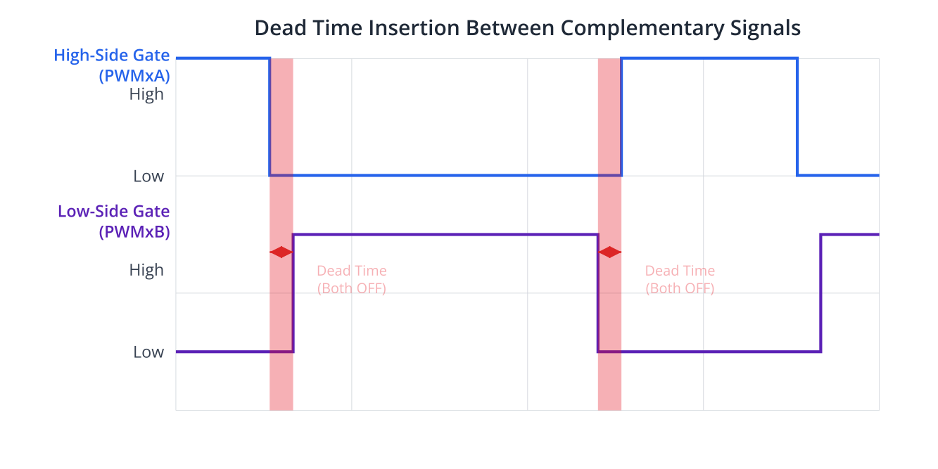
Dead Time (also known as blanking time) is a short, intentional delay inserted between the turn-OFF command of one switch in a complementary pair and the turn-ON command of the other switch. During this dead time, both switches in the leg are commanded to be OFF, ensuring that the first switch has fully turned off before the second one begins to turn on.
MCPWM Dead Time Module (ESP-IDF v5.x Perspective)
The ESP32’s MCPWM peripheral includes a dedicated dead-time module that can be configured for each operator. This module automatically generates the necessary delays for complementary PWM outputs.
- Association: Dead time is configured at the operator level and applies to the pair of generators (e.g., Generator A and Generator B) associated with that operator.
- Configuration Parameters (
mcpwm_dead_time_config_t):posedge_delay_ticks: This is the dead time inserted before a rising edge is generated on the non-inverted output (e.g., PWMxA) and before a corresponding falling edge is generated on the inverted output (e.g., PWMxB). It effectively delays the turning ON of the switch that would create the rising edge on the primary output. The value is in terms of MCPWM timer clock ticks (derived fromresolution_hzof the timer associated with the operator).negedge_delay_ticks: This is the dead time inserted before a falling edge is generated on the non-inverted output (e.g., PWMxA) and before a corresponding rising edge is generated on the inverted output (e.g., PWMxB). It effectively delays the turning ON of the switch that would create the rising edge on the complementary output (which corresponds to the falling edge of the primary output).flags.invert_output_a/flags.invert_output_b: These flags determine which generator’s output (A or B) is considered the primary (non-inverted) and which is the complementary (inverted).- Example: If
invert_output_a = falseandinvert_output_b = true, then Generator A’s output (e.g., PWMxA) is the primary signal, and Generator B’s output (PWMxB) will be its active-low complement with dead time.
- Example: If
- Application:
mcpwm_operator_apply_deadtime(oper_handle, &dead_time_config)applies the configuration.
Active High Complementary (AHC) vs. Active Low Complementary (ALC):
The ESP32 MCPWM typically generates an active high primary signal (e.g., PWMxA) and an active low complementary signal (e.g., PWMxB) when invert_output_b = true.
- AHC (PWMxA): The primary signal directly follows the intended PWM logic (e.g., high during the duty cycle).
- ALC (PWMxB): The complementary signal is high when PWMxA is low, and low when PWMxA is high, with dead times ensuring no overlap.
Calculating Dead Time Values:
The required dead time depends on the switching characteristics of the MOSFETs/IGBTs used in the power stage:
t_d_on: Turn-on delay time.t_r: Rise time.t_d_off: Turn-off delay time.t_f: Fall time.
A safe dead time (t_dead) should be greater than the worst-case turn-off time of one switch and the worst-case turn-on time of the complementary switch.
Generally: t_dead > max(t_d_off + t_f) of one switch and t_dead > max(t_d_on + t_r) of the other, but more practically, ensure the switch turning off is fully off before the other begins to turn on.
A common rule of thumb: Dead Time > (Max Turn-Off Delay + Max Fall Time) – (Min Turn-On Delay + Min Rise Time). However, it’s often simpler and safer to ensure Dead Time > Max Total Turn-Off Time of one device and Dead Time > Max Total Turn-On Time of the other, and pick the larger.
Consult the MOSFET/IGBT datasheets. The posedge_delay_ticks and negedge_delay_ticks are then t_dead / (1 / timer_resolution_hz).
Fault Detection
Motor drive systems can experience various fault conditions that can damage the motor, the drive electronics, or pose a safety risk. The MCPWM peripheral provides mechanisms to detect external fault signals and take predefined actions.
Common Fault Sources:
- Over-Current: Current through the motor or inverter exceeds safe limits (e.g., due to a short circuit, stalled motor, or overload). Often detected by shunt resistors and comparators/op-amps.
- Over-Voltage: DC bus voltage exceeds the rated limits (e.g., due to regenerative braking without proper handling).
- Under-Voltage: DC bus voltage drops too low, potentially causing improper operation of gate drivers or logic.
- Over-Temperature: Power switches, motor, or driver board overheat. Detected by thermistors or temperature sensors.
- External Emergency Stop: A manual E-stop button.
MCPWM Fault Input Mechanisms:
The primary way to signal external faults to the MCPWM peripheral is through dedicated GPIO pins configured as fault inputs.
- GPIO-Based Fault Inputs (
mcpwm_new_gpio_fault()):- You can configure one or more GPIO pins as fault inputs for an MCPWM group.
mcpwm_gpio_fault_config_t:group_id: The MCPWM group this fault belongs to.gpio_num: The GPIO pin to use as the fault input.active_level:MCPWM_FAULT_ACTIVE_HIGHorMCPWM_FAULT_ACTIVE_LOW, defines whether a high or low signal on the GPIO triggers the fault.flags.io_loop_back: For testing, can loop back a GPIO output to this fault input.flags.pull_up/flags.pull_down: Enable internal pull-up/down resistors for the fault GPIO.
- Comparator-Based Faults (Internal): Some microcontrollers have analog comparators that can directly trigger peripheral actions. While ESP32 has analog comparators, their direct linkage to MCPWM fault inputs as a standard feature is less common than GPIO-based faults for external fault signals. The MCPWM’s own internal comparators (used for PWM generation) are distinct from these. For external analog faults (like overcurrent from a shunt), you’d typically use an external analog comparator IC whose digital output then feeds into an MCPWM GPIO fault input.
Fault Actions on PWM Generators:
When a configured fault event occurs, the MCPWM unit can automatically force its PWM generator outputs to a predefined safe state. This is configured using mcpwm_generator_set_actions_on_fault_event().
mcpwm_generator_set_actions_on_fault_event(gen_handle, actions_config):actions_config: This is a variable-argument structure usingMCPWM_GEN_FAULT_EVENT_ACTION()macros.- For each fault event (e.g., fault from
fault_handle_0while timer is counting up/down), you specify an action for the generator:MCPWM_GEN_ACTION_LOW: Force output low.MCPWM_GEN_ACTION_HIGH: Force output high.MCPWM_GEN_ACTION_TOGGLE: Toggle output (less common for faults).MCPWM_GEN_ACTION_KEEP: Keep current state (rarely used for active fault response).
- Trip Modes:
- Cycle-by-Cycle Trip (
MCPWM_FAULT_EVENT_ON_TIMER_CYCLE): If this mode is selected for the fault action, the PWM output is forced to the defined state (e.g., low) as long as the fault condition is active. If the fault signal de-asserts, the PWM output automatically resumes normal operation on the next PWM cycle (or based on timer events like TEZ/TEP). This is useful for transient faults where automatic recovery is desired. - One-Shot (Latched) Trip (
MCPWM_FAULT_EVENT_ON_TIMER_ONESHOT): If this mode is selected, once the fault is detected, the PWM output is forced to the defined state and remains in that state even if the fault signal de-asserts. The PWM operation will not resume automatically. A software intervention is typically required to clear the latched fault and re-enable PWM. This is suitable for critical faults that require inspection or manual reset.
- Cycle-by-Cycle Trip (

Fault Event Callbacks:
To allow software to react to fault events (e.g., log the fault, notify the user, initiate a system shutdown sequence), you can register callback functions.
mcpwm_fault_register_event_callbacks(fault_handle, &callbacks, user_data):mcpwm_fault_event_callbacks_t:.on_fault_enter: Function pointer called when the fault becomes active..on_fault_exit: Function pointer called when the fault becomes inactive (relevant for cycle-by-cycle or if monitoring fault release).
- These callbacks are executed in an ISR context, so they must be fast and avoid blocking operations.
Fault Recovery:
For one-shot (latched) faults, the MCPWM peripheral needs to be explicitly told to clear the fault condition before normal PWM operation can resume.
mcpwm_fault_recover(fault_handle): This function attempts to clear the latched fault condition associated withfault_handle. After recovery, if the external fault signal is no longer active, the PWM generators previously affected by this one-shot fault can resume operation.
Practical Examples
Common Setup for Examples:
Ensure you have the ESP-IDF environment set up (Chapter 2). Include necessary headers:
#include <stdio.h>
#include "freertos/FreeRTOS.h"
#include "freertos/task.h"
#include "esp_log.h"
#include "driver/mcpwm_prelude.h"
#include "driver/gpio.h" // For fault GPIO if not part of MCPWM config struct

static const char *TAG = "mcpwm_safety_features";

// MCPWM handles (declare globally or pass around as needed)
mcpwm_timer_handle_t timer = NULL;
mcpwm_oper_handle_t oper = NULL;
mcpwm_cmpr_handle_t comparator = NULL;
mcpwm_gen_handle_t generator_a = NULL; // For PWMxA
mcpwm_gen_handle_t generator_b = NULL; // For PWMxB (complementary)
mcpwm_fault_handle_t gpio_fault = NULL;

// GPIO definitions
#define PWM_A_GPIO 13 // Example GPIO for PWMxA
#define PWM_B_GPIO 12 // Example GPIO for PWMxB
#define FAULT_INPUT_GPIO 4 // Example GPIO for fault signal

// PWM Configuration
#define PWM_TIMER_RESOLUTION_HZ 1000000 // 1MHz, 1us tick
#define PWM_FREQUENCY_HZ 20000          // 20kHz
#define PWM_PERIOD_TICKS (PWM_TIMER_RESOLUTION_HZ / (2 * PWM_FREQUENCY_HZ)) // For UP_DOWN count
Example 1: Precise Dead-Time Configuration and Verification
This example demonstrates configuring complementary PWM signals with specific dead times and how to verify them.
void init_pwm_with_dead_time(uint32_t dead_time_posedge_us, uint32_t dead_time_negedge_us) {
    ESP_LOGI(TAG, "Create timer");
    mcpwm_timer_config_t timer_config = {
        .group_id = 0,
        .clk_src = MCPWM_TIMER_CLK_SRC_DEFAULT,
        .resolution_hz = PWM_TIMER_RESOLUTION_HZ,
        .period_ticks = PWM_PERIOD_TICKS,
        .count_mode = MCPWM_TIMER_COUNT_MODE_UP_DOWN, // Symmetric PWM
    };
    ESP_ERROR_CHECK(mcpwm_new_timer(&timer_config, &timer));

    ESP_LOGI(TAG, "Create operator");
    mcpwm_operator_config_t oper_config = {.group_id = 0};
    ESP_ERROR_CHECK(mcpwm_new_operator(&oper_config, &oper));
    ESP_ERROR_CHECK(mcpwm_operator_connect_timer(oper, timer));

    ESP_LOGI(TAG, "Create comparator");
    mcpwm_comparator_config_t comp_config = {.flags.update_cmp_on_tez = true};
    ESP_ERROR_CHECK(mcpwm_new_comparator(oper, &comp_config, &comparator));
    // Set initial duty cycle (e.g., 50%)
    ESP_ERROR_CHECK(mcpwm_comparator_set_compare_value(comparator, PWM_PERIOD_TICKS / 2));

    ESP_LOGI(TAG, "Create generator A (PWMxA) on GPIO %d", PWM_A_GPIO);
    mcpwm_generator_config_t gen_a_config = {.gen_gpio_num = PWM_A_GPIO};
    ESP_ERROR_CHECK(mcpwm_new_generator(oper, &gen_a_config, &generator_a));

    ESP_LOGI(TAG, "Create generator B (PWMxB) on GPIO %d", PWM_B_GPIO);
    mcpwm_generator_config_t gen_b_config = {.gen_gpio_num = PWM_B_GPIO};
    ESP_ERROR_CHECK(mcpwm_new_generator(oper, &gen_b_config, &generator_b));

    // Configure actions for symmetric PWM (PWMxA active high)
    ESP_ERROR_CHECK(mcpwm_generator_set_actions_on_timer_event(generator_a,
        MCPWM_GEN_TIMER_EVENT_ACTION(MCPWM_TIMER_EVENT_EMPTY, MCPWM_GEN_ACTION_HIGH, 0),
        MCPWM_GEN_TIMER_EVENT_ACTION_END()));
    ESP_ERROR_CHECK(mcpwm_generator_set_actions_on_compare_event(generator_a,
        MCPWM_GEN_COMPARE_EVENT_ACTION(MCPWM_TIMER_DIRECTION_UP, comparator, MCPWM_GEN_ACTION_LOW),
        MCPWM_GEN_COMPARE_EVENT_ACTION(MCPWM_TIMER_DIRECTION_DOWN, comparator, MCPWM_GEN_ACTION_HIGH),
        MCPWM_GEN_COMPARE_EVENT_ACTION_END()));
    // Generator B will be made complementary by the dead-time module.

    ESP_LOGI(TAG, "Enable dead time: Posedge %.1fus, Negedge %.1fus", (float)dead_time_posedge_us, (float)dead_time_negedge_us);
    mcpwm_dead_time_config_t dt_config = {
        .posedge_delay_ticks = dead_time_posedge_us, // Assuming 1 tick = 1us
        .negedge_delay_ticks = dead_time_negedge_us, // Assuming 1 tick = 1us
        .flags.invert_output_a = false, // PWMxA is active high (primary)
        .flags.invert_output_b = true,  // PWMxB is active low complementary to PWMxA
    };
    ESP_ERROR_CHECK(mcpwm_operator_apply_deadtime(oper, &dt_config));

    ESP_LOGI(TAG, "Enable and start timer");
    ESP_ERROR_CHECK(mcpwm_timer_enable(timer));
    ESP_ERROR_CHECK(mcpwm_timer_start_stop(timer, MCPWM_TIMER_START_NO_STOP));
    ESP_LOGI(TAG, "Complementary PWM with Dead-Time Initialized.");
}
Build Instructions:
- Save the code.
- Add to
app_main:init_pwm_with_dead_time(2, 3); // 2us posedge, 3us negedge deadtime - Build:
idf.py build.
Run/Flash/Observe:
- Flash:
idf.py -p (YourPort) flash monitor. - Verification (Oscilloscope Required):
- Connect Oscilloscope Channel 1 to
PWM_A_GPIOand Channel 2 toPWM_B_GPIO. - Trigger on the rising edge of Channel 1 (PWMxA).
- Observe Rising Edge Dead Time (
posedge_delay_ticks):- Zoom in on the transition where PWMxA goes LOW and PWMxB goes HIGH.
- Measure the time from PWMxA’s falling edge to PWMxB’s rising edge. This should correspond to
negedge_delay_ticks(because PWMxB is inverted, its rising edge corresponds to PWMxA’s falling edge, which is affected bynegedge_delay_tickson PWMxA). - Alternatively, observe where PWMxA goes HIGH and PWMxB goes LOW. Measure the time from PWMxB’s falling edge to PWMxA’s rising edge. This should correspond to
posedge_delay_ticks.
- Observe Falling Edge Dead Time (
negedge_delay_ticks):- Zoom in on the transition where PWMxA goes HIGH and PWMxB goes LOW.
- Measure the time from PWMxA’s rising edge to PWMxB’s falling edge. This should correspond to
posedge_delay_tickson PWMxA.
- It’s crucial to understand how
posedge_delay_ticksandnegedge_delay_ticksapply to the non-inverted signal (PWMxA in this case) and how that translates to the inverted signal (PWMxB). posedge_delay_ticksdelays the ON-transition of the switch driven by PWMxA (and thus the ON-transition of the switch driven by PWMxB’s LOW state).negedge_delay_ticksdelays the ON-transition of the switch driven by PWMxB (and thus the ON-transition of the switch driven by PWMxA’s LOW state).
- Connect Oscilloscope Channel 1 to
Example 2: GPIO-Based Fault Input (One-Shot Trip)
This example configures a GPIO as an active-high fault input. If the fault occurs, PWM outputs are forced low (latched).
// Fault event callback (IRAM_ATTR for ISR context)
static bool IRAM_ATTR on_fault_enter_callback(mcpwm_fault_handle_t fault, const mcpwm_fault_event_data_t *edata, void *user_data) {
    // For ISR-safe logging, use ets_printf or set a flag for a task
    ets_printf("FAULT DETECTED on GPIO %d! PWM outputs latched low.\n", FAULT_INPUT_GPIO);
    // Example: Increment a counter passed via user_data
    // int *fault_count = (int *)user_data;
    // (*fault_count)++;
    return false; // No high-priority task woken
}

void init_fault_detection_oneshot(void) {
    // Assume init_pwm_with_dead_time() or similar PWM setup has been called,
    // so 'oper', 'generator_a', 'generator_b' are initialized.

    ESP_LOGI(TAG, "Configure GPIO fault input (One-Shot)");
    mcpwm_gpio_fault_config_t fault_config = {
        .group_id = 0,
        .gpio_num = FAULT_INPUT_GPIO,
        .active_level = MCPWM_FAULT_ACTIVE_HIGH, // Fault on high level
        .flags.pull_down = true, // Ensure defined state if fault signal floats low
    };
    ESP_ERROR_CHECK(mcpwm_new_gpio_fault(&fault_config, &gpio_fault));

    ESP_LOGI(TAG, "Set generator actions on one-shot fault");
    // Force PWMxA (generator_a) and PWMxB (generator_b) low on fault
    // Actions for Generator A
    ESP_ERROR_CHECK(mcpwm_generator_set_actions_on_fault_event(generator_a,
        MCPWM_GEN_FAULT_EVENT_ACTION(MCPWM_FAULT_EVENT_ON_TIMER_ONESHOT, MCPWM_TIMER_DIRECTION_UP, gpio_fault, MCPWM_GEN_ACTION_LOW),
        MCPWM_GEN_FAULT_EVENT_ACTION(MCPWM_FAULT_EVENT_ON_TIMER_ONESHOT, MCPWM_TIMER_DIRECTION_DOWN, gpio_fault, MCPWM_GEN_ACTION_LOW),
        MCPWM_GEN_FAULT_EVENT_ACTION_END()));
    // Actions for Generator B
    ESP_ERROR_CHECK(mcpwm_generator_set_actions_on_fault_event(generator_b,
        MCPWM_GEN_FAULT_EVENT_ACTION(MCPWM_FAULT_EVENT_ON_TIMER_ONESHOT, MCPWM_TIMER_DIRECTION_UP, gpio_fault, MCPWM_GEN_ACTION_LOW),
        MCPWM_GEN_FAULT_EVENT_ACTION(MCPWM_FAULT_EVENT_ON_TIMER_ONESHOT, MCPWM_TIMER_DIRECTION_DOWN, gpio_fault, MCPWM_GEN_ACTION_LOW),
        MCPWM_GEN_FAULT_EVENT_ACTION_END()));

    ESP_LOGI(TAG, "Register fault event callback");
    mcpwm_fault_event_callbacks_t cbs = {
        .on_fault_enter = on_fault_enter_callback,
        // .on_fault_exit can also be registered if needed
    };
    ESP_ERROR_CHECK(mcpwm_fault_register_event_callbacks(gpio_fault, &cbs, NULL)); // Pass user_data if needed

    ESP_LOGI(TAG, "One-Shot Fault detection initialized for GPIO %d.", FAULT_INPUT_GPIO);
}

void app_main_example2(void) {
    ESP_LOGI(TAG, "Initializing PWM with Dead Time...");
    init_pwm_with_dead_time(2, 2); // 2us dead time for both edges

    ESP_LOGI(TAG, "Initializing One-Shot Fault Detection...");
    init_fault_detection_oneshot();

    ESP_LOGI(TAG, "PWM running. Connect GPIO %d to 3.3V to trigger fault.", FAULT_INPUT_GPIO);

    // Example: To demonstrate recovery later
    vTaskDelay(pdMS_TO_TICKS(15000)); // Wait 15 seconds

    if (gpio_fault) { // Check if fault handler was created
        ESP_LOGI(TAG, "Attempting to recover from fault...");
        // Ensure fault condition is externally cleared before calling recover
        // For this test, assume we'd manually disconnect GPIO 4 from 3.3V
        ESP_ERROR_CHECK(mcpwm_fault_recover(gpio_fault));
        ESP_LOGI(TAG, "Fault recovery attempted. PWM should resume if fault source is clear.");
    }

    while(1) {
        vTaskDelay(pdMS_TO_TICKS(1000));
    }
}
Build and Run: Similar to Example 1. Use app_main_example2 as app_main.
Observe:
- PWM signals should be active on
PWM_A_GPIOandPWM_B_GPIO. - Connect
FAULT_INPUT_GPIO(GPIO 4) to 3.3V (VCC). - The serial monitor should print “FAULT DETECTED…”.
- Both PWM outputs should go low and stay low, even if you disconnect GPIO 4 from 3.3V.
- After about 15 seconds (due to
vTaskDelay), the code attemptsmcpwm_fault_recover(). If GPIO 4 was disconnected from 3.3V (fault source cleared) before this call, the PWM should resume.
Example 3: Cycle-by-Cycle Fault Trip and Auto-Recovery
This example modifies the fault action to cycle-by-cycle, where PWM resumes automatically if the fault clears.
void init_fault_detection_cbc(void) {
    // Assume init_pwm_with_dead_time() or similar PWM setup has been called.

    ESP_LOGI(TAG, "Configure GPIO fault input (Cycle-by-Cycle)");
    mcpwm_gpio_fault_config_t fault_config = {
        .group_id = 0,
        .gpio_num = FAULT_INPUT_GPIO,
        .active_level = MCPWM_FAULT_ACTIVE_HIGH,
        .flags.pull_down = true,
    };
    // Reuse gpio_fault handle or create a new one if managing multiple fault types
    if (gpio_fault) { // Delete previous fault if any, to reconfigure
        mcpwm_del_fault(gpio_fault);
        gpio_fault = NULL;
    }
    ESP_ERROR_CHECK(mcpwm_new_gpio_fault(&fault_config, &gpio_fault));

    ESP_LOGI(TAG, "Set generator actions on cycle-by-cycle fault");
    // Actions for Generator A
    ESP_ERROR_CHECK(mcpwm_generator_set_actions_on_fault_event(generator_a,
        MCPWM_GEN_FAULT_EVENT_ACTION(MCPWM_FAULT_EVENT_ON_TIMER_CYCLE, MCPWM_TIMER_DIRECTION_UP, gpio_fault, MCPWM_GEN_ACTION_LOW),
        MCPWM_GEN_FAULT_EVENT_ACTION(MCPWM_FAULT_EVENT_ON_TIMER_CYCLE, MCPWM_TIMER_DIRECTION_DOWN, gpio_fault, MCPWM_GEN_ACTION_LOW),
        MCPWM_GEN_FAULT_EVENT_ACTION_END()));
    // Actions for Generator B
    ESP_ERROR_CHECK(mcpwm_generator_set_actions_on_fault_event(generator_b,
        MCPWM_GEN_FAULT_EVENT_ACTION(MCPWM_FAULT_EVENT_ON_TIMER_CYCLE, MCPWM_TIMER_DIRECTION_UP, gpio_fault, MCPWM_GEN_ACTION_LOW),
        MCPWM_GEN_FAULT_EVENT_ACTION(MCPWM_FAULT_EVENT_ON_TIMER_CYCLE, MCPWM_TIMER_DIRECTION_DOWN, gpio_fault, MCPWM_GEN_ACTION_LOW),
        MCPWM_GEN_FAULT_EVENT_ACTION_END()));

    // Register callback (can reuse on_fault_enter_callback)
    mcpwm_fault_event_callbacks_t cbs = {.on_fault_enter = on_fault_enter_callback};
    ESP_ERROR_CHECK(mcpwm_fault_register_event_callbacks(gpio_fault, &cbs, NULL));

    ESP_LOGI(TAG, "Cycle-by-Cycle Fault detection initialized for GPIO %d.", FAULT_INPUT_GPIO);
}

void app_main_example3(void) {
    ESP_LOGI(TAG, "Initializing PWM with Dead Time...");
    init_pwm_with_dead_time(2, 2);

    ESP_LOGI(TAG, "Initializing Cycle-by-Cycle Fault Detection...");
    init_fault_detection_cbc();

    ESP_LOGI(TAG, "PWM running. Connect GPIO %d to 3.3V to trigger fault (PWM stops). Disconnect to resume.", FAULT_INPUT_GPIO);

    while(1) {
        vTaskDelay(pdMS_TO_TICKS(1000));
    }
}
Build and Run: Similar to Example 1. Use app_main_example3 as app_main.
Observe:
- PWM signals active.
- Connect
FAULT_INPUT_GPIOto 3.3V. PWM outputs go low. - Disconnect
FAULT_INPUT_GPIOfrom 3.3V (fault source clears). - PWM outputs should automatically resume normal operation.
Variant Notes
The MCPWM dead time and fault detection capabilities are generally consistent across the ESP32 variants that include the MCPWM peripheral (ESP32, ESP32-S2, ESP32-S3, ESP32-C3, ESP32-C6, ESP32-H2).
- Number of Fault Inputs: Each MCPWM group typically supports a certain number of GPIO-based fault inputs (e.g., 3 fault inputs per group on original ESP32). Consult the specific variant’s Technical Reference Manual (TRM) for exact numbers if you need multiple independent fault sources. The ESP-IDF driver manages the allocation.
- Dead Time Resolution: The precision of the dead time (duration of one
tick) is determined by theresolution_hzof the MCPWM timer to which the operator is connected. This is configurable and consistent. - API Consistency: The ESP-IDF v5.x
mcpwm_prelude.hAPI aims to provide a uniform interface across variants. Configuration structures (mcpwm_dead_time_config_t,mcpwm_gpio_fault_config_t) and functions are generally the same. - Internal Connections: While the examples focus on GPIO-based fault inputs, some variants might have internal connections from other peripherals (like analog comparators) that could potentially be routed to trigger MCPWM actions, though this is advanced and less standardized via the high-level MCPWM driver. For most common external faults, GPIO inputs are the standard method.
Always refer to the latest ESP-IDF documentation and the TRM for your specific ESP32 variant if you encounter limitations or require highly specific configurations.
Common Mistakes & Troubleshooting Tips
| Mistake / Issue | Symptom(s) | Troubleshooting / Solution |
|---|---|---|
| Incorrect Dead Time Unit | Driver IC gets hot, or is destroyed. Power supply trips. | You set dead time in microseconds instead of timer ticks. Solution: Convert from seconds to ticks: ticks = dead_time_seconds * timer_resolution_hz. Always start with a conservative (larger) dead time. |
| Spurious Fault Triggers | Fault handler triggers randomly when no fault exists. PWM stops unexpectedly. | The fault input GPIO pin is likely floating. Solution: Enable the internal pull-up or pull-down resistor to give the pin a defined default state. Set flags.pull_up = true or flags.pull_down = true in the fault config, opposite to the active level. |
| Fault Not Detected | A real fault (e.g., over-current signal asserted) occurs, but the MCPWM continues operating normally. | 1. Wrong Polarity: active_level is set incorrectly (e.g., to HIGH when the signal goes LOW on fault). Solution: Verify the fault signal’s logic level and correct the config. 2. Wrong GPIO: The fault is wired to a different GPIO than configured. Solution: Double-check your wiring and the gpio_num in your code. |
| PWM Does Not Recover from One-Shot Fault | Fault condition is fixed, but the PWM output remains off. | This is the expected behavior for One-Shot trip. A software reset is required. Solution: After ensuring the external fault is clear, your code must explicitly call mcpwm_fault_recover(fault_handle) to re-enable PWM outputs. |
| ISR Crashes or System Hangs on Fault | System becomes unstable or reboots when a fault occurs. | The fault callback function is likely performing a blocking operation. Solution: Keep ISR code minimal. Use ets_printf for debug output. For complex logic, set a flag or use a queue to signal a regular FreeRTOS task. Ensure the callback is marked with IRAM_ATTR. |
Exercises
- Dead Time Optimization for a Specific MOSFET:
- Obtain the datasheet for a common power MOSFET (e.g., IRFZ44N, though this is an older part, a more modern logic-level one would be better for direct ESP32 drive if not using a dedicated gate driver).
- Identify the maximum
t_d(off)(turn-off delay) andt_f(fall time), and maximumt_d(on)(turn-on delay) andt_r(rise time). - Calculate a safe minimum dead time required.
- Configure the MCPWM in Example 1 with this calculated dead time (converted to ticks) for both
posedge_delay_ticksandnegedge_delay_ticks. - Verify the dead time precisely using an oscilloscope. Try slightly reducing it (if safe margins allow) and observe if any issues arise (e.g., increased noise, though shoot-through itself is hard to see without current probes and risks damage).
- Latched Fault with Manual Reset and LED Indicator:
- Use Example 2 (One-Shot Fault).
- Add an LED connected to another GPIO. In the
on_fault_enter_callback, turn this LED ON to indicate a latched fault. - Configure a pushbutton connected to another GPIO.
- In your main loop or a separate task, poll this pushbutton. When pressed (after a fault has occurred and the LED is ON):
- Call
mcpwm_fault_recover(gpio_fault). - Turn the fault indicator LED OFF.
- Log that the fault has been manually reset.
- Call
- Ensure the actual fault condition (e.g.,
FAULT_INPUT_GPIOhigh) is removed before attempting recovery.
- Integrating Fault Detection into BLDC Control (from Chapter 163):
- Take the BLDC motor control code from Chapter 163.
- Add a new fault input GPIO (e.g., simulating an over-current signal from the BLDC driver).
- Configure this as a one-shot fault.
- When this fault occurs, modify the
mcpwm_generator_set_actions_on_fault_eventfor all six BLDC phase generators (U_H, U_L, V_H, V_L, W_H, W_L) to force them all to a safe state (e.g., all low, or all high-impedance by forcing both high and low side of each phase off if your driver supports it). - Implement a fault callback to log the BLDC fault.
- Test by running the BLDC motor and then asserting the fault signal. The motor should stop, and the PWMs should be disabled.
Summary
- Dead Time is crucial in complementary PWM schemes (like H-bridges and 3-phase inverters) to prevent shoot-through, a damaging short-circuit condition caused by simultaneous conduction of high-side and low-side switches in a leg.
- The ESP32 MCPWM allows precise configuration of
posedge_delay_ticksandnegedge_delay_ticksalong with output inversion to automatically generate dead time. - Fault Detection enables the MCPWM to react to external error signals (e.g., over-current, over-temperature) by forcing PWM outputs to a safe, predefined state.
- Faults are typically signaled via GPIO inputs configured with specific active levels.
- MCPWM supports two main fault trip modes:
- Cycle-by-Cycle Trip: PWM automatically resumes if the fault condition clears.
- One-Shot (Latched) Trip: PWM remains in the fault state until explicitly reset by software using
mcpwm_fault_recover().
- Fault event callbacks (
on_fault_enter,on_fault_exit) allow software to be notified and react to fault occurrences. - Properly configuring dead time and fault handling significantly enhances the safety, reliability, and longevity of motor control systems and power electronics.
Further Reading
- ESP-IDF Programming Guide: MCPWM Driver: (Refer to the sections on Dead Time and Fault Handling)
- https://docs.espressif.com/projects/esp-idf/en/stable/esp32/api-reference/peripherals/mcpwm.html (Adjust link for your specific ESP32 target and IDF version if necessary).
- Application Notes on Gate Driver Design and Shoot-Through Prevention:
- Search for application notes from power semiconductor manufacturers (e.g., Texas Instruments, Infineon, STMicroelectronics, OnSemi) on topics like “MOSFET gate drivers,” “shoot-through prevention,” “dead time control.”
- Technical Reference Manual (TRM) for your specific ESP32 variant:
- Provides the most detailed hardware-level information about the MCPWM peripheral’s capabilities. Available on the Espressif website.
