
Chapter 145: LED PWM Controller (LEDC) of ESP32
Chapter Objectives
By the end of this chapter, you will be able to:
- Understand the detailed architecture and components of the ESP32 LEDC peripheral.
- Configure LEDC timers for specific frequencies and duty cycle resolutions.
- Configure LEDC channels to output PWM signals on GPIOs for LED control.
- Precisely control LED brightness by setting specific duty cycle values.
- Implement smooth LED fading effects using both manual duty cycle updates and LEDC hardware fading capabilities.
- Control multiple LEDs or an RGB LED using multiple LEDC channels.
- Understand the implications of frequency and resolution choices for LED control.
- Be aware of advanced LEDC features like phase control and interrupts (briefly).
Introduction
In the previous chapter, we introduced the concept of Pulse Width Modulation (PWM) and its general application in embedded systems. We also briefly mentioned that the ESP32 family provides the LED Control (LEDC) peripheral as a primary means for generating PWM signals, especially well-suited for controlling LEDs. This chapter will take a much deeper dive into the LEDC peripheral.
We will explore its architecture, configuration options, and practical applications for precise LED brightness control, creating dynamic lighting effects like fading, and even managing multiple LEDs or color components of an RGB LED. Mastering the LEDC peripheral is crucial for any ESP32 project involving sophisticated visual feedback or illumination.
Theory
The LEDC (LED Control) peripheral is a flexible PWM generator found in ESP32 series SoCs. While its name suggests a primary use for LEDs, it’s versatile enough for other tasks requiring PWM signals, such as simple motor control or generating tones, as long as the frequency and resolution requirements are met.
LEDC Architecture Deep Dive
The LEDC peripheral is composed of several key blocks:
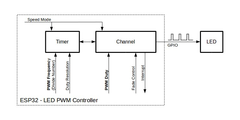
- LEDC Timers (or Speed Mode Timers):
- Function: These timers are the fundamental frequency generators for the PWM signals. Each timer can be configured to produce a base clock at a specific frequency.
- Speed Modes:
- On ESP32 (classic), ESP32-S2, and ESP32-S3, timers are grouped into High-Speed (HS) and Low-Speed (LS) modes. There are typically 4 HS timers and 4 LS timers.
- On ESP32-C3, ESP32-C6, and ESP32-H2, the distinction is less rigid; timers can be configured for either mode, but the total number is fixed (e.g., 4 timers for C3/C6, 2 for H2).
- Clock Sources: LEDC timers can be driven by various clock sources. The
LEDC_AUTO_CLKoption in the configuration structure usually selects the APB_CLK (typically 80 MHz) or REF_TICK (typically 1 MHz) based on the desired frequency and resolution. You can also manually select a clock source (LEDC_USE_APB_CLK,LEDC_USE_REF_TICK, orLEDC_USE_RTC8M_CLKon some variants for low-speed mode). - Frequency Calculation: The PWM frequency (freq_hz) is determined by the source clock frequency and the timer’s counter range (which is tied to the duty resolution):freq_hz = source_clk_freq / (2^duty_resolution)Or, if a specific clock divider is used internally by the driver for more precision:freq_hz = source_clk_freq / divider / (2^duty_resolution)The driver handles these calculations when LEDC_AUTO_CLK is used.
- Duty Resolution: This defines the number of bits used to represent the duty cycle, ranging from
LEDC_TIMER_1_BITtoLEDC_TIMER_20_BIT(max resolution depends on the variant and speed mode). A higher resolution means more steps and finer control over the duty cycle. For example,LEDC_TIMER_10_BITprovides 210 = 1024 steps (0 to 1023).
ledc_timer_config_t Member |
Description | Common Values / Notes |
|---|---|---|
| speed_mode | LEDC speed mode for the timer. |
LEDC_HIGH_SPEED_MODE, LEDC_LOW_SPEED_MODE. On ESP32, S2, S3, distinct HS/LS blocks. On C3, C6, H2, timers are configurable for either mode from a unified pool. |
| timer_num | The LEDC timer to configure. |
LEDC_TIMER_0, LEDC_TIMER_1, etc. (up to available timers on the variant). E.g., ESP32 has 4 HS & 4 LS timers. ESP32-H2 has 2 unified timers. |
| duty_resolution | Resolution of the PWM duty cycle for this timer. Defines the range of the counter (0 to 2resolution-1). |
LEDC_TIMER_1_BIT to LEDC_TIMER_20_BIT (max varies by variant/mode). E.g., LEDC_TIMER_10_BIT (1024 steps). Higher resolution allows finer brightness control but impacts max frequency. |
| freq_hz | Desired PWM signal frequency in Hertz. |
E.g., 5000 (5 kHz for general LED dimming), 1000 (1 kHz). Actual frequency depends on source clock and resolution: freq_hz = src_clk / (2^res). Driver attempts to match. |
| clk_cfg | Clock source configuration for the timer. |
LEDC_AUTO_CLK: Recommended. Driver selects best source (APB_CLK, REF_TICK) and divider. LEDC_USE_APB_CLK: Typically 80 MHz. LEDC_USE_REF_TICK: Typically 1 MHz. LEDC_USE_RTC8M_CLK / LEDC_USE_XTAL_CLK: Variant-specific options, often for low-speed modes or specific clocking needs. |
- LEDC Channels:
- Function: Channels are responsible for generating the actual PWM output signal on a specific GPIO pin. Each channel is associated with one of the LEDC timers.
- Speed Modes: Similar to timers, channels operate in HS or LS mode. An HS channel must be driven by an HS timer, and an LS channel by an LS timer. On variants with unified resources, the mode is configured per channel.
- GPIO Mapping: Each channel is mapped to a physical GPIO pin through the GPIO matrix, making pin selection highly flexible.
- Duty Cycle Control: The primary function of a channel is to set and update the duty cycle of the PWM signal it generates. The duty cycle value is compared against the counter of its associated timer.
ledc_set_duty(speed_mode, channel_num, duty_val): Sets the target duty value.ledc_update_duty(speed_mode, channel_num): Applies the duty value set byledc_set_duty.
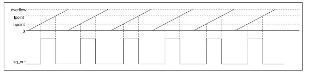
- Hpoint (Horizontal Point / Phase Control): Each channel has an
hpointregister. This value determines the phase of the PWM signal by defining the timer count value at which the duty cycle begins. For most simple LED dimming,hpointis set to 0. By using differenthpointvalues for channels sharing the same timer, you can create phase-shifted PWM signals.
ledc_channel_config_t Member |
Description | Common Values / Notes |
|---|---|---|
| gpio_num | The GPIO pin number to output the PWM signal. | Any valid digital output GPIO pin (check variant datasheet). E.g., 2, 4, 16. |
| speed_mode | LEDC speed mode for the channel. | Must match the speed_mode of the selected timer_sel. |
| channel | The LEDC channel to configure. | LEDC_CHANNEL_0, LEDC_CHANNEL_1, etc. (up to available channels). |
| intr_type | Interrupt type for the channel. |
LEDC_INTR_DISABLE: No interrupt. LEDC_INTR_FADE_END: Interrupt on hardware fade completion. Useful for non-blocking fades. |
| timer_sel | Selects the LEDC timer to be used as the source for this channel. | LEDC_TIMER_0, LEDC_TIMER_1, etc. Must be a configured timer. |
| duty | Initial duty cycle value for the channel. |
Range is 0 to (1 << duty_resolution) - 1. E.g., for 10-bit resolution, 0 to 1023. Set with ledc_set_duty() and applied with ledc_update_duty() later for dynamic changes. |
| hpoint | Horizontal point register value. Controls the phase of the PWM signal. |
Typically 0 for standard PWM. Range 0 to (1 << duty_resolution) - 1. Non-zero values shift the start of the duty cycle pulse relative to the timer’s counter, allowing phase control between channels sharing a timer. |
| flags.output_invert (ESP-IDF v5.0+) | Invert the PWM signal output. |
0: Normal output (default). 1: Inverted output. Useful for common anode LEDs or specific driver logic. For older IDF versions, this might not be part of the struct directly. |
- Hardware Fading:
- The LEDC peripheral includes hardware support for automatically and smoothly changing the duty cycle from a start value to a target value over a specified duration and with a defined step. This offloads the CPU from manually implementing fade loops.
- Functions like
ledc_set_fade_with_time(),ledc_set_fade_with_step(),ledc_fade_start()are used to configure and initiate hardware fades. - Fading can be blocking or non-blocking (using fade-end interrupts).
graph TD
    A[Start: LEDC Hardware Fade]:::startNode --> B("1- Install Fade Service <br> <i>ledc_fade_func_install(0)</i> <br> (Call once globally)");
    style A fill:#EDE9FE,stroke:#5B21B6,stroke-width:2px,color:#5B21B6;
    style B fill:#DBEAFE,stroke:#2563EB,stroke-width:1px,color:#1E40AF;

    B --> C{Timer & Channel Configured?};
    style C fill:#FEF3C7,stroke:#D97706,stroke-width:1px,color:#92400E;
    C -- No --> PreReq["Ensure LEDC Timer & Channel <br> are initialized first <br> (<i>ledc_timer_config</i>, <i>ledc_channel_config</i>)"]:::checkNode;
    PreReq --> C;

    C -- Yes --> D("2- Configure Fade Parameters <br> e.g., <i>ledc_set_fade_with_time(...)</i> <br> - Target Duty <br> - Fade Duration (ms)");
    style D fill:#DBEAFE,stroke:#2563EB,stroke-width:1px,color:#1E40AF;

    D --> E{Choose Fade Mode};
    style E fill:#FEF3C7,stroke:#D97706,stroke-width:1px,color:#92400E;

    E -- Blocking Fade --> F("3a- Start Blocking Fade <br> <i>ledc_fade_start(..., LEDC_FADE_WAIT_DONE)</i>");
    style F fill:#DBEAFE,stroke:#2563EB,stroke-width:1px,color:#1E40AF;
    F --> G[Fade Completes. <br> Function Returns.];
    style G fill:#D1FAE5,stroke:#059669,stroke-width:2px,color:#065F46;

    E -- Non-Blocking Fade --> H("3b- Start Non-Blocking Fade <br> <i>ledc_fade_start(..., LEDC_FADE_NO_WAIT)</i>");
    style H fill:#DBEAFE,stroke:#2563EB,stroke-width:1px,color:#1E40AF;
    H --> I{"Fade End Interrupt Enabled? <br> (intr_type = LEDC_INTR_FADE_END)"};
    style I fill:#FEF3C7,stroke:#D97706,stroke-width:1px,color:#92400E;

    I -- Yes --> J("Handle Fade Completion in ISR <br> (Registered via <i>ledc_isr_register</i>)");
    style J fill:#DBEAFE,stroke:#2563EB,stroke-width:1px,color:#1E40AF;
    J --> K[Fade Completes. <br> ISR Notifies Application.];
    style K fill:#D1FAE5,stroke:#059669,stroke-width:2px,color:#065F46;

    I -- No --> L("Application must poll <br> or use another sync method <br> (e.g., <i>ledc_get_fade_done_status</i> - not a direct API, conceptual polling)");
    style L fill:#FEE2E2,stroke:#DC2626,stroke-width:1px,color:#991B1B;
    L --> M[Fade Completes. <br> Application Detects.];
    style M fill:#D1FAE5,stroke:#059669,stroke-width:2px,color:#065F46;

    G --> Z{More Fades or End?};
    K --> Z;
    M --> Z;
    style Z fill:#FEF3C7,stroke:#D97706,stroke-width:1px,color:#92400E;
    Z -- More Fades --> D;
    Z -- End --> EndNode[End Fade Operations];
    style EndNode fill:#D1FAE5,stroke:#059669,stroke-width:2px,color:#065F46;

    classDef startNode fill:#EDE9FE,stroke:#5B21B6,stroke-width:2px,color:#5B21B6;
    classDef processNode fill:#DBEAFE,stroke:#2563EB,stroke-width:1px,color:#1E40AF;
    classDef decisionNode fill:#FEF3C7,stroke:#D97706,stroke-width:1px,color:#92400E;
    classDef endNode fill:#D1FAE5,stroke:#059669,stroke-width:2px,color:#065F46;
    classDef checkNode fill:#FEE2E2,stroke:#DC2626,stroke-width:1px,color:#991B1B;
| Function Signature | Purpose | Key Parameters / Notes |
|---|---|---|
| esp_err_t ledc_fade_func_install(int intr_alloc_flags) | Initializes the LEDC fade service. Must be called once before using hardware fade functions. | intr_alloc_flags: Flags for interrupt allocation. 0 for default. |
| esp_err_t ledc_fade_func_uninstall(void) | Uninstalls the LEDC fade service. | Call when hardware fading is no longer needed to free resources. |
| esp_err_t ledc_set_fade_with_time(ledc_mode_t speed_mode, ledc_channel_t channel, uint32_t target_duty, int max_fade_time_ms) | Configures a fade to a target_duty over a specified max_fade_time_ms. |
target_duty: The final duty cycle value (0 to 2res-1). max_fade_time_ms: Duration of the fade in milliseconds. |
| esp_err_t ledc_set_fade_with_step(ledc_mode_t speed_mode, ledc_channel_t channel, uint32_t target_duty, uint32_t scale, uint32_t cycle_num) | Configures a fade by specifying the duty cycle change (scale) per number of PWM cycles (cycle_num). | More complex control over fade steps. ledc_set_fade_with_time is often easier for simple time-based fades. |
| esp_err_t ledc_fade_start(ledc_mode_t speed_mode, ledc_channel_t channel, ledc_fade_mode_t fade_mode) | Starts the configured fade operation on the specified channel. |
fade_mode: – LEDC_FADE_WAIT_DONE: Blocking call; returns after fade completion. – LEDC_FADE_NO_WAIT: Non-blocking; returns immediately. Use with LEDC_INTR_FADE_END interrupt or polling. |
| esp_err_t ledc_stop(ledc_mode_t speed_mode, ledc_channel_t channel, uint32_t idle_level) | Stops PWM signal generation on a channel and sets the output to idle_level. Can also stop ongoing fades. | idle_level: 0 or 1. |
- Interrupts:
- LEDC channels can generate interrupts, most notably when a hardware fade operation completes (
LEDC_INTR_FADE_END). This allows for event-driven control flow rather than polling. - Interrupts are configured in the
ledc_channel_config_tstructure and handled vialedc_isr_register(). For basic LED control, interrupts are often not necessary.
- LEDC channels can generate interrupts, most notably when a hardware fade operation completes (
graph TD
    subgraph GlobalClocks ["Clock Sources"]
        direction LR
        CLK_APB["APB_CLK (e.g., 80MHz)"]:::processNode
        CLK_REF["REF_TICK (e.g., 1MHz)"]:::processNode
        CLK_XTAL["XTAL_CLK (Variant Specific)"]:::processNode
        CLK_RTC["RTC8M_CLK (Variant Specific)"]:::processNode
    end
    style GlobalClocks fill:#f9f9f9,stroke:#ccc,stroke-width:1px

    subgraph LEDC_Peripheral ["LEDC Peripheral"]
        direction TB

        subgraph TimerGroup ["LEDC Timers (Speed Mode Specific or Unified)"]
            direction TB
            Timer0["Timer 0 (HS/LS or Unified)"]:::timerStyle
            Timer1["Timer N (HS/LS or Unified)"]:::timerStyle

            Timer0 -- "Config: Freq, Resolution" --> Timer0_Details["Set Frequency (freq_hz)<br>- Set Duty Resolution (e.g., 10-bit)<br>- Clock Source Selection (clk_cfg)<br>- Speed Mode (HS/LS)"]:::detailsStyle
            Timer1 -- "Config: Freq, Resolution" --> Timer1_Details["Set Frequency (freq_hz)<br>- Set Duty Resolution (e.g., 8-bit)<br>- Clock Source Selection (clk_cfg)<br>- Speed Mode (HS/LS)"]:::detailsStyle
        end
        style TimerGroup fill:#e6e6fa,stroke:#9370db,stroke-width:1.5px

        subgraph ChannelGroup ["LEDC Channels"]
            direction TB
            Channel0["Channel 0"]:::channelStyle
            Channel1["Channel 1"]:::channelStyle
            ChannelX["Channel X"]:::channelStyle
            ChannelY["Channel Y"]:::channelStyle

            Channel0 -- "Config: GPIO, Duty, Hpoint, Fade" --> Chan0_Details["GPIO Pin Mapping<br>- Initial Duty<br>- Hpoint (Phase)<br>- Interrupt Type<br>- Hardware Fade Unit"]:::detailsStyle
            Channel1 -- "Config: GPIO, Duty, Hpoint, Fade" --> Chan1_Details["GPIO Pin Mapping<br>- Initial Duty<br>- Hpoint (Phase)<br>- Interrupt Type<br>- Hardware Fade Unit"]:::detailsStyle
            ChannelX -- "Config: GPIO, Duty, Hpoint, Fade" --> ChanX_Details["GPIO Pin Mapping<br>- Initial Duty<br>- Hpoint (Phase)<br>- Interrupt Type<br>- Hardware Fade Unit"]:::detailsStyle
            ChannelY -- "Config: GPIO, Duty, Hpoint, Fade" --> ChanY_Details["GPIO Pin Mapping<br>- Initial Duty<br>- Hpoint (Phase)<br>- Interrupt Type<br>- Hardware Fade Unit"]:::detailsStyle
        end
        style ChannelGroup fill:#e0ffff,stroke:#00ced1,stroke-width:1.5px

        Timer0 --> Channel0
        Timer0 --> Channel1
        Timer1 --> ChannelX
        Timer1 --> ChannelY

        Channel0 --> PWM_Out0[PWM Output GPIO_A]:::outputStyle
        Channel1 --> PWM_Out1[PWM Output GPIO_B]:::outputStyle
        ChannelX --> PWM_OutX[PWM Output GPIO_C]:::outputStyle
        ChannelY --> PWM_OutY[PWM Output GPIO_D]:::outputStyle
    end
    style LEDC_Peripheral fill:#fff0f5,stroke:#db7093,stroke-width:2px

    GlobalClocks -.-> Timer0
    GlobalClocks -.-> Timer1

    classDef timerStyle fill:#EDE9FE,stroke:#5B21B6,stroke-width:2px,color:#5B21B6
    classDef channelStyle fill:#DBEAFE,stroke:#2563EB,stroke-width:2px,color:#1E40AF
    classDef outputStyle fill:#D1FAE5,stroke:#059669,stroke-width:2px,color:#065F46
    classDef detailsStyle fill:#FEF3C7,stroke:#D97706,stroke-width:1px,color:#92400E,fontSize:10px
    classDef processNode fill:#DBEAFE,stroke:#2563EB,stroke-width:1px,color:#1E40AF
Frequency, Resolution, and LED Perception
- Frequency: For LEDs, the PWM frequency should be high enough to avoid visible flicker. Human eyes typically stop perceiving flicker above 100-200 Hz, but higher frequencies (1 kHz to 20 kHz or more) are often used to ensure smoothness, especially if the LED or the observer is moving, or if camera recording is involved. Very high frequencies can sometimes lead to reduced efficiency in LED drivers or introduce EMI. For typical LED dimming, 1 kHz to 5 kHz is a common range.
- Resolution: Higher resolution provides more brightness levels. For example:
- 8-bit resolution (0-255): 256 brightness levels.
- 10-bit resolution (0-1023): 1024 brightness levels.
- 12-bit resolution (0-4095): 4096 brightness levels.More levels result in smoother dimming, especially at the lower end of the brightness scale.
- Trade-off: As seen in the frequency calculation formula, for a fixed source clock, increasing resolution will decrease the maximum achievable PWM frequency, and vice-versa.max_freq_hz = source_clk_freq / (2^duty_resolution)The LEDC_AUTO_CLK setting helps the driver pick the best internal clock and dividers to achieve the desired freq_hz and duty_resolution if possible.
| Duty Resolution (Bits) | Counter Range (2Resolution) | Max Achievable Frequency (Hz) freq = 80MHz / Counter Range |
Brightness Steps | Suitability Notes |
|---|---|---|---|---|
| LEDC_TIMER_8_BIT (8 bits) | 256 | 80,000,000 / 256 = 312,500 Hz (312.5 kHz) | 256 | Good for many LED applications, decent steps, high frequency possible. |
| LEDC_TIMER_10_BIT (10 bits) | 1024 | 80,000,000 / 1024 ≈ 78,125 Hz (78.1 kHz) | 1024 | Very good for smooth LED dimming, good balance. |
| LEDC_TIMER_12_BIT (12 bits) | 4096 | 80,000,000 / 4096 ≈ 19,531 Hz (19.5 kHz) | 4096 | Excellent smoothness, frequency still good for LEDs. |
| LEDC_TIMER_14_BIT (14 bits) | 16384 | 80,000,000 / 16384 ≈ 4,882 Hz (4.88 kHz) | 16384 | Very high resolution, frequency suitable for most LED tasks. |
| LEDC_TIMER_16_BIT (16 bits) | 65536 | 80,000,000 / 65536 ≈ 1,220 Hz (1.22 kHz) | 65536 | Extremely fine control, frequency still above common flicker perception. |
| LEDC_TIMER_20_BIT (20 bits) | 1,048,576 | 80,000,000 / 1,048,576 ≈ 76 Hz | 1,048,576 | Maximal resolution, but frequency may be too low for some LED applications (potential flicker). REF_TICK (1MHz) might be auto-selected by driver for higher frequencies at high resolutions if APB_CLK is too fast. |
Note: These are conceptual calculations. The LEDC_AUTO_CLK setting in ESP-IDF will attempt to select the best internal clock source (e.g., APB_CLK, REF_TICK) and dividers to achieve the target freq_hz for the chosen duty_resolution. The actual maximum frequency can also be limited by the specific ESP32 variant. Always consult the datasheet and ESP-IDF documentation.
Gamma Correction (Brief Mention)
Human perception of brightness is non-linear. A linear increase in PWM duty cycle does not result in a linear perceived increase in brightness. LEDs themselves also have a non-linear response. To achieve a visually linear dimming effect (where 50% duty cycle looks like half brightness), gamma correction is often applied. This involves mapping the desired linear brightness to a non-linear duty cycle value using a power function.
duty_cycle_corrected = ((desired_brightness / max_brightness) ^ gamma) * max_duty_value
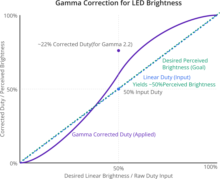
A common gamma value for displays is 2.2. While full gamma correction is beyond this chapter’s basic scope, it’s an important concept for professional LED applications. For simple dimming, a linear duty cycle change is often acceptable.
Practical Examples
Let’s explore how to use the LEDC peripheral for various LED control tasks. Assume the same hardware setup as Chapter 144 (LED + resistor on a GPIO).
Example 1: Setting Precise LED Brightness Levels
This example demonstrates setting an LED to specific brightness percentages using a 10-bit resolution.
Software (main.c):
#include <stdio.h>
#include "freertos/FreeRTOS.h"
#include "freertos/task.h"
#include "driver/ledc.h"
#include "esp_err.h"
#include "esp_log.h" // For ESP_LOGx

#define LEDC_TAG "LEDC_Brightness"

// Define the GPIO pin for the LED
#define LEDC_OUTPUT_GPIO (2) // Example: GPIO2.

// LEDC Configuration
#define LEDC_HS_TIMER          LEDC_TIMER_0
#define LEDC_HS_MODE           LEDC_HIGH_SPEED_MODE
#define LEDC_HS_CHANNEL        LEDC_CHANNEL_0
#define LEDC_DUTY_RES          LEDC_TIMER_10_BIT // 10-bit resolution (0-1023)
#define LEDC_FREQUENCY         (5000) // 5 kHz

// Helper function to set brightness percentage
void set_led_brightness(uint8_t percentage) {
    if (percentage > 100) {
        percentage = 100;
    }
    uint32_t max_duty = (1 << LEDC_DUTY_RES) - 1; // Max duty for 10-bit is 1023
    uint32_t duty_cycle = (max_duty * percentage) / 100;

    ESP_LOGI(LEDC_TAG, "Setting brightness to %u%%, duty: %lu", percentage, duty_cycle);
    ESP_ERROR_CHECK(ledc_set_duty(LEDC_HS_MODE, LEDC_HS_CHANNEL, duty_cycle));
    ESP_ERROR_CHECK(ledc_update_duty(LEDC_HS_MODE, LEDC_HS_CHANNEL));
}

void app_main(void)
{
    // 1. Configure LEDC Timer
    ledc_timer_config_t ledc_timer = {
        .speed_mode       = LEDC_HS_MODE,
        .timer_num        = LEDC_HS_TIMER,
        .duty_resolution  = LEDC_DUTY_RES,
        .freq_hz          = LEDC_FREQUENCY,
        .clk_cfg          = LEDC_AUTO_CLK
    };
    ESP_ERROR_CHECK(ledc_timer_config(&ledc_timer));
    ESP_LOGI(LEDC_TAG, "LEDC timer configured.");

    // 2. Configure LEDC Channel
    ledc_channel_config_t ledc_channel = {
        .speed_mode     = LEDC_HS_MODE,
        .channel        = LEDC_HS_CHANNEL,
        .timer_sel      = LEDC_HS_TIMER,
        .intr_type      = LEDC_INTR_DISABLE,
        .gpio_num       = LEDC_OUTPUT_GPIO,
        .duty           = 0, // Initial duty: 0 (LED OFF)
        .hpoint         = 0
    };
    ESP_ERROR_CHECK(ledc_channel_config(&ledc_channel));
    ESP_LOGI(LEDC_TAG, "LEDC channel configured for GPIO %d.", LEDC_OUTPUT_GPIO);

    // 3. Set different brightness levels
    while (1) {
        set_led_brightness(0); // Off
        vTaskDelay(pdMS_TO_TICKS(2000));

        set_led_brightness(10); // 10%
        vTaskDelay(pdMS_TO_TICKS(2000));

        set_led_brightness(50); // 50%
        vTaskDelay(pdMS_TO_TICKS(2000));

        set_led_brightness(90); // 90%
        vTaskDelay(pdMS_TO_TICKS(2000));

        set_led_brightness(100); // Full
        vTaskDelay(pdMS_TO_TICKS(2000));
    }
}
Code Explanation:
set_led_brightness(uint8_t percentage): This helper function takes a percentage (0-100) and calculates the corresponding duty cycle value based onLEDC_DUTY_RES.- The
app_maininitializes the LEDC timer and channel as before. - The main loop then calls
set_led_brightnesswith different percentages, holding each brightness level for 2 seconds.
Build/Flash/Observe:
Build and flash this code. You should see the LED turn ON at different distinct brightness levels (off, very dim, medium, bright, full brightness). The serial monitor will log the percentage and corresponding raw duty value.
Example 2: LEDC Hardware Fading
This example demonstrates using the LEDC peripheral’s built-in hardware fading capability to smoothly transition LED brightness.
Software (main.c):
#include <stdio.h>
#include "freertos/FreeRTOS.h"
#include "freertos/task.h"
#include "driver/ledc.h"
#include "esp_err.h"
#include "esp_log.h"

#define LEDC_TAG "LEDC_HardwareFade"

#define LEDC_OUTPUT_GPIO    (2)
#define LEDC_HS_TIMER       LEDC_TIMER_0
#define LEDC_HS_MODE        LEDC_HIGH_SPEED_MODE
#define LEDC_HS_CHANNEL     LEDC_CHANNEL_0
#define LEDC_DUTY_RES       LEDC_TIMER_10_BIT // 10-bit (0-1023)
#define LEDC_FREQUENCY      (5000) // 5 kHz

#define FADE_TIME_MS        (1500) // Fade duration in milliseconds

void app_main(void)
{
    // 1. Configure LEDC Timer
    ledc_timer_config_t ledc_timer = {
        .speed_mode       = LEDC_HS_MODE,
        .duty_resolution  = LEDC_DUTY_RES,
        .timer_num        = LEDC_HS_TIMER,
        .freq_hz          = LEDC_FREQUENCY,
        .clk_cfg          = LEDC_AUTO_CLK
    };
    ESP_ERROR_CHECK(ledc_timer_config(&ledc_timer));

    // 2. Configure LEDC Channel
    ledc_channel_config_t ledc_channel = {
        .speed_mode     = LEDC_HS_MODE,
        .channel        = LEDC_HS_CHANNEL,
        .timer_sel      = LEDC_HS_TIMER,
        .intr_type      = LEDC_INTR_FADE_END, // Enable fade end interrupt (optional, but good practice)
        .gpio_num       = LEDC_OUTPUT_GPIO,
        .duty           = 0, // Initial duty
        .hpoint         = 0
    };
    ESP_ERROR_CHECK(ledc_channel_config(&ledc_channel));

    // 3. Install fade service (needed for hardware fading)
    ESP_LOGI(LEDC_TAG, "Installing fade function...");
    ESP_ERROR_CHECK(ledc_fade_func_install(0)); // Argument is interrupt allocation flags, 0 for default

    uint32_t max_duty = (1 << LEDC_DUTY_RES) - 1; // 1023 for 10-bit

    ESP_LOGI(LEDC_TAG, "Starting hardware fade loop...");
    while (1) {
        // Fade to MAX brightness
        ESP_LOGI(LEDC_TAG, "Fading to ON (duty: %lu)", max_duty);
        ESP_ERROR_CHECK(ledc_set_fade_with_time(LEDC_HS_MODE, LEDC_HS_CHANNEL, max_duty, FADE_TIME_MS));
        ESP_ERROR_CHECK(ledc_fade_start(LEDC_HS_MODE, LEDC_HS_CHANNEL, LEDC_FADE_WAIT_DONE)); // Blocking fade
        ESP_LOGI(LEDC_TAG, "Fade ON complete.");
        vTaskDelay(pdMS_TO_TICKS(500)); // Wait at max brightness

        // Fade to MIN brightness (0)
        ESP_LOGI(LEDC_TAG, "Fading to OFF (duty: 0)");
        ESP_ERROR_CHECK(ledc_set_fade_with_time(LEDC_HS_MODE, LEDC_HS_CHANNEL, 0, FADE_TIME_MS));
        ESP_ERROR_CHECK(ledc_fade_start(LEDC_HS_MODE, LEDC_HS_CHANNEL, LEDC_FADE_WAIT_DONE)); // Blocking fade
        ESP_LOGI(LEDC_TAG, "Fade OFF complete.");
        vTaskDelay(pdMS_TO_TICKS(500)); // Wait at min brightness
    }
}
Code Explanation:
ledc_fade_func_install(0): This function must be called once before using any hardware fade functions. It installs the LEDC fade service.ledc_set_fade_with_time(mode, channel, target_duty, max_fade_time_ms): Configures the fade.target_duty: The duty cycle value to fade to.max_fade_time_ms: The duration of the fade.
ledc_fade_start(mode, channel, fade_mode): Starts the fade.LEDC_FADE_WAIT_DONE: Makes the call blocking; it will return only after the fade is complete.LEDC_FADE_NO_WAIT: Makes the call non-blocking; it returns immediately. You would typically use theLEDC_INTR_FADE_ENDinterrupt to know when the fade is finished.
- The
intr_typeinledc_channel_config_tis set toLEDC_INTR_FADE_END. While this example uses blocking fades, enabling the interrupt type is good practice if you later switch to non-blocking fades.
Build/Flash/Observe:
The LED should now smoothly fade in to full brightness over 1.5 seconds and then smoothly fade out to off over 1.5 seconds, repeatedly. The fading should appear smoother than the manual loop in Chapter 144 because the hardware handles the intermediate steps.
Example 3: Controlling an RGB LED
An RGB LED typically has four pins: one common anode (+) or common cathode (-), and one pin for each color component (Red, Green, Blue). By controlling the brightness of each component using separate PWM signals, you can mix colors.
Hardware:
- Common Anode RGB LED: Common pin to 3.3V. R, G, B pins to ESP32 GPIOs via current-limiting resistors (one for each color).
- Common Cathode RGB LED: Common pin to GND. R, G, B pins to ESP32 GPIOs via current-limiting resistors.
- Choose three GPIOs for R, G, B. E.g., GPIO2 (R), GPIO4 (G), GPIO5 (B).
- Three resistors (e.g., 220-330Ω, values might differ for R, G, B to achieve white balance).

Software (main.c):
#include <stdio.h>
#include "freertos/FreeRTOS.h"
#include "freertos/task.h"
#include "driver/ledc.h"
#include "esp_err.h"
#include "esp_log.h"

#define LEDC_TAG "LEDC_RGB"

// GPIOs for RGB LED (adjust as per your wiring)
#define RGB_R_GPIO (2)
#define RGB_G_GPIO (4)
#define RGB_B_GPIO (5)

// LEDC Configuration (shared timer, different channels)
#define LEDC_HS_TIMER       LEDC_TIMER_0
#define LEDC_HS_MODE        LEDC_HIGH_SPEED_MODE
#define LEDC_DUTY_RES       LEDC_TIMER_8_BIT // 8-bit (0-255) for simpler color values
#define LEDC_FREQUENCY      (1000) // 1 kHz

// LEDC Channels for R, G, B
#define LEDC_R_CHANNEL      LEDC_CHANNEL_0
#define LEDC_G_CHANNEL      LEDC_CHANNEL_1
#define LEDC_B_CHANNEL      LEDC_CHANNEL_2

// Helper to set RGB color
void set_rgb_color(uint8_t r, uint8_t g, uint8_t b) {
    // Assuming 8-bit resolution, duty values are directly r, g, b
    ESP_ERROR_CHECK(ledc_set_duty(LEDC_HS_MODE, LEDC_R_CHANNEL, r));
    ESP_ERROR_CHECK(ledc_update_duty(LEDC_HS_MODE, LEDC_R_CHANNEL));

    ESP_ERROR_CHECK(ledc_set_duty(LEDC_HS_MODE, LEDC_G_CHANNEL, g));
    ESP_ERROR_CHECK(ledc_update_duty(LEDC_HS_MODE, LEDC_G_CHANNEL));

    ESP_ERROR_CHECK(ledc_set_duty(LEDC_HS_MODE, LEDC_B_CHANNEL, b));
    ESP_ERROR_CHECK(ledc_update_duty(LEDC_HS_MODE, LEDC_B_CHANNEL));
    ESP_LOGI(LEDC_TAG, "Set RGB: R=%u, G=%u, B=%u", r, g, b);
}

void app_main(void)
{
    // 1. Configure ONE LEDC Timer (shared by all channels)
    ledc_timer_config_t ledc_timer = {
        .speed_mode       = LEDC_HS_MODE,
        .timer_num        = LEDC_HS_TIMER,
        .duty_resolution  = LEDC_DUTY_RES,
        .freq_hz          = LEDC_FREQUENCY,
        .clk_cfg          = LEDC_AUTO_CLK
    };
    ESP_ERROR_CHECK(ledc_timer_config(&ledc_timer));
    ESP_LOGI(LEDC_TAG, "Shared LEDC timer configured.");

    // 2. Configure LEDC Channel for RED
    ledc_channel_config_t r_channel_conf = {
        .speed_mode     = LEDC_HS_MODE,
        .channel        = LEDC_R_CHANNEL,
        .timer_sel      = LEDC_HS_TIMER,
        .intr_type      = LEDC_INTR_DISABLE,
        .gpio_num       = RGB_R_GPIO,
        .duty           = 0, .hpoint = 0
    };
    ESP_ERROR_CHECK(ledc_channel_config(&r_channel_conf));

    // 3. Configure LEDC Channel for GREEN
    ledc_channel_config_t g_channel_conf = {
        .speed_mode     = LEDC_HS_MODE,
        .channel        = LEDC_G_CHANNEL,
        .timer_sel      = LEDC_HS_TIMER,
        .intr_type      = LEDC_INTR_DISABLE,
        .gpio_num       = RGB_G_GPIO,
        .duty           = 0, .hpoint = 0
    };
    ESP_ERROR_CHECK(ledc_channel_config(&g_channel_conf));

    // 4. Configure LEDC Channel for BLUE
    ledc_channel_config_t b_channel_conf = {
        .speed_mode     = LEDC_HS_MODE,
        .channel        = LEDC_B_CHANNEL,
        .timer_sel      = LEDC_HS_TIMER,
        .intr_type      = LEDC_INTR_DISABLE,
        .gpio_num       = RGB_B_GPIO,
        .duty           = 0, .hpoint = 0
    };
    ESP_ERROR_CHECK(ledc_channel_config(&b_channel_conf));
    ESP_LOGI(LEDC_TAG, "RGB LEDC channels configured.");

    // Cycle through some colors
    while (1) {
        set_rgb_color(255, 0, 0);   // Red
        vTaskDelay(pdMS_TO_TICKS(1500));
        set_rgb_color(0, 255, 0);   // Green
        vTaskDelay(pdMS_TO_TICKS(1500));
        set_rgb_color(0, 0, 255);   // Blue
        vTaskDelay(pdMS_TO_TICKS(1500));
        set_rgb_color(255, 255, 0); // Yellow
        vTaskDelay(pdMS_TO_TICKS(1500));
        set_rgb_color(0, 255, 255); // Cyan
        vTaskDelay(pdMS_TO_TICKS(1500));
        set_rgb_color(255, 0, 255); // Magenta
        vTaskDelay(pdMS_TO_TICKS(1500));
        set_rgb_color(255, 255, 255); // White
        vTaskDelay(pdMS_TO_TICKS(1500));
        set_rgb_color(0, 0, 0);     // Off
        vTaskDelay(pdMS_TO_TICKS(1500));
    }
}
Code Explanation:
- Three LEDC channels (
LEDC_R_CHANNEL,LEDC_G_CHANNEL,LEDC_B_CHANNEL) are configured. - All three channels share the same LEDC timer (
LEDC_HS_TIMER), ensuring their PWM signals are synchronized in frequency. LEDC_DUTY_RESis set toLEDC_TIMER_8_BIT(0-255) for convenience with common RGB color values.- The
set_rgb_colorfunction updates the duty cycle for each channel independently.
Build/Flash/Observe:
Your RGB LED should cycle through Red, Green, Blue, Yellow, Cyan, Magenta, White, and Off.
Tip: Achieving a perfect “white” might require adjusting the R, G, B duty cycle values due to differences in LED efficiency and human eye sensitivity to different colors. This is where color calibration comes into play for more advanced applications.
Variant Notes
The LEDC peripheral’s core functionality and API are largely consistent across ESP32 variants that feature it. The main differences lie in the number of available resources:
| Feature | ESP32 (Classic) | ESP32-S2 | ESP32-S3 | ESP32-C3 | ESP32-C6 | ESP32-H2 |
|---|---|---|---|---|---|---|
| LEDC Timers | 4 HS, 4 LS | 4 HS, 4 LS | 4 HS, 4 LS | 4 (shared HS/LS) | 4 (shared HS/LS) | 2 (shared HS/LS) |
| LEDC Channels | 8 HS, 8 LS | 8 HS, 8 LS | 8 HS, 8 LS | 6 (shared HS/LS) | 8 (shared HS/LS) | 4 (shared HS/LS) |
| Max Duty Resolution | HS: up to 20-bit LS: up to 14-bit (IDF supports up to 15/14) |
HS: up to 20-bit LS: up to 14-bit (IDF supports up to 15/14) |
HS: up to 20-bit LS: up to 14-bit (IDF supports up to 15/14) |
Up to 14-bit (IDF supports up to 14) | Up to 14-bit (IDF supports up to 14) | Up to 14-bit (IDF supports up to 14) |
| Typical Clock Sources | APB_CLK, REF_TICK, RTC8M_CLK (LS only) | APB_CLK, REF_TICK, XTAL_CLK (LS only) | APB_CLK, REF_TICK, XTAL_CLK (LS only) | APB_CLK, REF_TICK, XTAL_CLK | APB_CLK, REF_TICK, XTAL_CLK, FOSC_CLK (for LP_PWM) | APB_CLK, REF_TICK, XTAL_CLK, FOSC_CLK (for LP_PWM) |
| Hardware Fading | Yes | Yes | Yes | Yes | Yes | Yes |
| LP_PWM Peripheral | No | No | No | No | Yes (1 unit, 6 ch) | Yes (1 unit, 2 ch) |
Note: “IDF supports up to X-bit” refers to the range defined by LEDC_TIMER_X_BIT macros. Actual achievable resolution also depends on frequency. Always refer to the latest ESP-IDF documentation and specific chip datasheet for authoritative details.
Key Considerations from Chapter 144, reiterated and expanded for LEDC:
- HS/LS Distinction: On ESP32, S2, S3, remember that HS timers can only drive HS channels, and LS timers only LS channels. For C3, C6, H2, timers and channels are more flexible but the total count is lower.
- Resource Limits: Be mindful of the total number of timers and channels available on your specific variant when designing applications with many PWM outputs. For example, an ESP32-H2 has only 4 channels total.
- Maximum Resolution: While the API might define up to 20 bits, the practically achievable resolution depends on the clock source and desired frequency. Higher resolutions are typically possible with lower PWM frequencies. The datasheets provide specifics.
- LP_PWM: For ultra-low-power LED applications on ESP32-C6 and H2, where PWM needs to operate during light sleep, the dedicated LP_PWM peripheral might be a better choice than LEDC, though its API and capabilities differ.
- GPIOs: Always verify GPIO compatibility for LEDC output in your variant’s datasheet.
Common Mistakes & Troubleshooting Tips
| Mistake / Issue | Symptom(s) | Troubleshooting / Solution |
|---|---|---|
| Forgetting ledc_fade_func_install() | Hardware fade functions (ledc_set_fade_with_time, ledc_fade_start) return error, assert, or don’t work. | Ensure ledc_fade_func_install(0) is called once during initialization before any hardware fade operations. |
| Incorrect Duty Cycle Range for Resolution | LED brightness is erratic, doesn’t scale as expected, or ledc_set_duty() / fade functions behave unexpectedly. | Calculate max_duty = (1 << LEDC_DUTY_RES) - 1. Ensure all duty values passed to LEDC functions are within 0 and max_duty. For example, for 10-bit resolution, max duty is 1023. |
| Issues with Multi-Channel Synchronization (e.g., RGB LED) | Colors are incorrect, flickering between components, or phases are visibly off. |
– Ensure all channels for a synchronized group (like RGB) use the same LEDC timer. – Typically, set hpoint = 0 for all such channels unless phase shifting is intentional and understood. – Verify all channels use the same speed_mode as their shared timer. |
| Hardware Fade Not Working (Non-Blocking Fade Misuse) | Fade seems to not happen, or next operation interferes if LEDC_FADE_NO_WAIT is used without proper handling. |
– If using LEDC_FADE_NO_WAIT, you must implement a way to detect fade completion. This usually involves: 1. Setting intr_type = LEDC_INTR_FADE_END in channel config. 2. Registering an ISR using ledc_isr_register() to handle the interrupt. – Alternatively, for simpler cases, use LEDC_FADE_WAIT_DONE for blocking fades. |
| Choosing Inappropriate Frequency or Resolution | Visible LED flicker (frequency too low). Coarse brightness steps (resolution too low). Inability to achieve desired frequency/resolution combination. |
– For LEDs, aim for frequency >100-200 Hz (1-5 kHz is common). – Choose resolution (e.g., 8 to 12 bits) for desired smoothness. – Understand the trade-off: max_freq ≈ src_clk / (2^resolution). LEDC_AUTO_CLK helps, but be aware of limits. |
| Timer/Channel Resource Exhaustion | ledc_timer_config() or ledc_channel_config() returns ESP_ERR_NOT_FOUND or ESP_ERR_NO_MEM. | Check the number of available timers/channels for your ESP32 variant (see Variant Notes table). Ensure you are not trying to configure more resources than available. Free unused timers/channels if possible. |
| Phase (Hpoint) Misconfiguration | PWM output starts at an unexpected point in its cycle, or multiple channels are out of sync when phase control is not intended. | For most simple LED applications, set hpoint = 0 in ledc_channel_config_t. Only use non-zero hpoint if deliberate phase-shifting between channels sharing a timer is required. |
Exercises
- Knight Rider Effect:
- Connect 4-6 individual LEDs to separate GPIOs.
- Configure an LEDC channel for each LED, all sharing the same timer.
- Create a “Knight Rider” scanning effect: one LED brightens and then dims, then the next one in sequence does the same, and so on, back and forth. Try using both manual duty updates and hardware fading for this.
- RGB Color Wheel with Hardware Fading:
- Using the RGB LED setup from Example 3, implement a smooth transition through the color spectrum (Red -> Yellow -> Green -> Cyan -> Blue -> Magenta -> Red).
- Use hardware fading for each R, G, B component to achieve smooth color changes. For example, to go from Red (255,0,0) to Yellow (255,255,0), fade G from 0 to 255 while R stays at 255 and B at 0.
- Brightness Control with Potentiometer (Links to ADC Chapter):
- Connect a potentiometer to an ADC input pin (refer to Chapter 126/127 for ADC).
- Read the ADC value and map it to the LEDC duty cycle range (0 to
(1 << LEDC_DUTY_RES) - 1). - Control the brightness of a single LED in real-time using the potentiometer.
- Investigate Frequency and Flicker:
- Set up a single LED with a fixed duty cycle (e.g., 50%).
- Experiment by changing the
LEDC_FREQUENCYto very low values (e.g., 10 Hz, 30 Hz, 50 Hz, 100 Hz) and then higher values (500 Hz, 1 kHz, 5 kHz). - Observe if and when you can perceive flicker. If you have a smartphone camera, try recording in slow-motion mode to see if it reveals flicker not obvious to the naked eye. Document your observations.
Summary
- The LEDC peripheral is a versatile PWM generator in ESP32s, ideal for LED brightness and color control.
- It consists of timers (setting frequency, resolution, speed mode) and channels (linking to GPIOs, timers, and controlling duty cycle/phase).
- Key configuration steps involve
ledc_timer_config()andledc_channel_config(). - Duty cycle is set with
ledc_set_duty()and applied withledc_update_duty(). - LEDC supports hardware fading for smooth, CPU-efficient brightness transitions, initialized with
ledc_fade_func_install()and controlled vialedc_set_fade_with_time()andledc_fade_start(). - Multiple LEDC channels can be used (sharing timers if synchronized frequency is needed) to control multiple LEDs or RGB color components.
- PWM frequency should be high enough to avoid flicker (typically >200Hz for LEDs). Resolution determines the number of brightness steps.
- Variant differences mainly concern the number of available timers and channels and their maximum resolution.
Further Reading
- ESP-IDF LED Control (LEDC) API Reference:
- Application Note on LEDC Fading: Search the Espressif website or ESP-IDF GitHub issues/examples for more advanced fading techniques or discussions.
- Gamma Correction for LEDs:
- Adafruit: LED Tricks: Gamma Correction
- SparkFun: Light and Color (discusses human perception)
