
Chapter 139: I2S Digital Microphone Integration
Chapter Objectives
By the end of this chapter, you will be able to:
- Understand the fundamentals of PDM (Pulse Density Modulation) and direct I2S digital microphones.
- Learn how to configure the ESP32 I2S peripheral for PDM receive (RX) mode using ESP-IDF v5.x.
- Interface with common PDM digital microphones (e.g., INMP441, SPH0645LM4H).
- Interface with digital microphones that provide a direct I2S output (e.g., ICS-43434).
- Understand the basics of how PDM data is converted to PCM (Pulse Code Modulation).
- Be aware of differences in PDM capabilities and configurations across various ESP32 variants.
- Identify common issues and troubleshoot digital microphone implementations.
Introduction
In the previous chapter, we explored the standard I2S protocol for transmitting and receiving digital audio. Building upon that foundation, this chapter focuses on a prevalent application: integrating digital microphones with ESP32 microcontrollers. Digital microphones are essential components in a myriad of modern embedded applications, including voice-activated assistants, environmental sound monitoring, audio recording devices, and sophisticated IoT systems.
Many popular digital MEMS (Micro-Electro-Mechanical Systems) microphones utilize Pulse Density Modulation (PDM) to output audio data. Others might provide a direct standard I2S output. The ESP32’s versatile I2S peripheral can be configured to interface with both types. We will delve into the theory of PDM, explore how the ESP32 handles PDM data, and provide practical examples for capturing audio from these tiny yet powerful sensors. Understanding digital microphone integration opens the door to creating more interactive and aware embedded projects.
Theory
What are Digital Microphones?
Digital microphones are typically MEMS-based sensors that convert acoustic sound waves directly into a digital data stream. Unlike analog microphones, which output a continuously varying voltage, digital microphones incorporate an Analog-to-Digital Converter (ADC) and signal conditioning circuitry within the microphone package itself.
Key Advantages of Digital Microphones:
- Noise Immunity: Digital signals are less susceptible to noise and interference picked up over traces and cables compared to analog signals. This is particularly beneficial in compact, noisy electronic environments.
- Simpler System Integration: They can often connect directly to a microcontroller’s digital interface (like I2S) without requiring an external preamplifier or ADC, reducing component count and board space.
- Miniaturization: MEMS technology allows for very small microphone packages.
Digital microphones commonly output audio data in one of two formats:
| Feature | PDM (Pulse Density Modulation) | Standard I2S (PCM Output) |
|---|---|---|
| Data Stream Type | 1-bit, high-frequency serial stream. | Multi-bit (e.g., 16, 24, 32-bit) PCM samples, serial stream. |
| Encoding Principle | Analog signal amplitude encoded by density of pulses. | Analog signal amplitude directly quantized into discrete levels. |
| Typical Clock Rate (to Mic) | High (e.g., 1 MHz – 4 MHz), significantly oversampled. ESP32 provides PDM_CLK. | Standard I2S Bit Clock (BCLK), e.g., SampleRate × Bits × Channels. ESP32 provides BCLK. |
| Conversion to PCM | Requires external decimation and low-pass filtering (often done by ESP32 I2S peripheral in PDM mode). | Outputs PCM directly; decimation/filtering already done inside the microphone. |
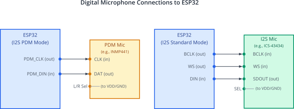
| Typical Signals (Mic to ESP32) | CLK (from ESP32), DAT (to ESP32), L/R Select (to VDD/GND). | BCLK (from ESP32), WS (from ESP32), SD/DOUT (to ESP32), SEL (if present). |
| ESP32 I2S Mode | PDM RX mode (driver/i2s_pdm.h). |
Standard I2S RX mode (driver/i2s_std.h). |
| Complexity on ESP32 | ESP32 handles PDM clocking and PDM-to-PCM conversion (decimation). | ESP32 handles standard I2S clocking and reads PCM data directly. |
| Example Microphones | INMP441, SPH0645LM4H, MSM261S4030H0. | ICS-43434. |
PDM (Pulse Density Modulation)
PDM is a method of representing an analog signal with a binary signal. In a PDM stream, the amplitude of the analog signal is encoded by the density of pulses in the digital output. A higher analog amplitude corresponds to a higher density of ‘1’s (or ‘0’s, depending on the encoding) in the PDM stream, and a lower amplitude corresponds to a lower density.
PDM Signal Characteristics:
- 1-bit Data Stream: The output is a sequence of single bits.
- High Clock Rate: PDM microphones are clocked at a much higher frequency (e.g., 1 MHz to 4 MHz, often 64 or 128 times the target audio sample rate) than the Nyquist rate of the audio signal itself. This is known as oversampling.
- Requires Decimation and Filtering: To convert the 1-bit high-frequency PDM stream into a usable multi-bit PCM audio format (e.g., 16-bit samples at a 16 kHz sample rate), the PDM signal must be processed by a decimation filter.
- Decimation: Reduces the sampling rate of the signal.
- Filtering (Low-pass): Removes the high-frequency quantization noise inherent in the PDM signal and shapes the audio spectrum.

PDM Microphone Interface Signals:
A typical PDM microphone requires at least two signals, and sometimes a third for stereo configurations:
- CLK (Clock): This clock signal is provided by the master (e.g., ESP32) to the PDM microphone. The microphone outputs one bit of data on each active clock edge.
- DAT (Data) / SD (Serial Data): This line carries the PDM data stream from the microphone to the master.
- L/R Sel (Left/Right Select) / WS (Word Select): For microphones that can operate as either left or right channels in a stereo pair. Tying this pin to VDD or GND typically selects the channel. For mono operation, it’s usually tied to select one specific channel (e.g., left).
| Signal Name | Abbreviation(s) | Direction (ESP32 Perspective) | Description |
|---|---|---|---|
| Clock | CLK, PDM_CLK | Output (ESP32 to Mic) | Clock signal provided by the ESP32 (master) to the PDM microphone. The microphone outputs one bit of data on each active clock edge. |
| Data | DAT, SD, PDM_DIN | Input (Mic to ESP32) | Carries the 1-bit PDM data stream from the microphone to the ESP32. |
| Left/Right Select | L/R Sel, SELECT, WS (sometimes) | Static Input (to Mic) | Typically tied to VDD or GND on the microphone board to select if the microphone outputs data for the Left or Right channel in a stereo setup, or to enable a specific channel for mono operation. Not usually connected to an active ESP32 signal for basic PDM. |
| Power | VDD, VCC | Output (ESP32 to Mic, or separate supply) | Power supply for the microphone (e.g., 1.8V to 3.3V). |
| Ground | GND | Common Reference | Ground reference. |
The ESP32’s I2S peripheral, when configured in PDM RX (receive) mode, can provide the CLK signal to the PDM microphone and receive the DAT signal. It also incorporates hardware decimation and filtering to convert the incoming PDM stream into PCM samples directly, which can then be read by the application.
Digital Microphones with Direct I2S Output
Some digital microphones, like the ICS-43434, directly output audio data in the standard I2S format. These microphones integrate the PDM-to-PCM conversion (decimation and filtering) internally.
Interfacing with Direct I2S Microphones:
- Standard I2S Protocol: They use the familiar SCK (BCLK), WS (LRCLK), and SD (DOUT from microphone) signals.
- Master/Slave Role: Typically, such microphones act as I2S slaves. The ESP32, acting as the I2S master, provides the BCLK and WS signals. The microphone then sends PCM data on its SD/DOUT line, which is connected to the ESP32’s I2S DIN pin.
- Simplified Processing: Since the output is already PCM, the ESP32 does not need to perform PDM decimation. It can read the data using the standard I2S RX mode configuration, as detailed in Chapter 138.
ESP-IDF I2S Driver for PDM (v5.x)
The ESP-IDF provides specific support for PDM input via the I2S peripheral. The key header file is driver/i2s_pdm.h.
Core Concepts for PDM RX:
- Channel Allocation: Similar to standard I2S, you first allocate an I2S channel handle (
i2s_chan_handle_t) for PDM reception.i2s_chan_config_t: Specifies the I2S port, role (I2S_ROLE_MASTERas ESP32 provides CLK), DMA settings.i2s_new_channel(): Allocates the channel. For PDM RX, the RX handle pointer is passed.
- PDM RX Mode Initialization: After channel allocation, initialize it for PDM RX mode.
i2s_pdm_rx_config_t: This is the main configuration structure for PDM input. It includes:clk_cfg: Of typei2s_pdm_rx_clk_config_t. Configures the PDM clock source, frequency (the clock supplied to the microphone), and decimation settings. TheI2S_PDM_RX_CLK_DEFAULT_CONFIG(pcm_sample_rate)macro is very helpful here. It automatically calculates the PDM clock frequency and decimation ratio based on your target PCM sample rate.slot_cfg: Of typei2s_pdm_rx_slot_config_t. Defines the output PCM data format (bit width, mono/stereo). TheI2S_PDM_RX_SLOT_DEFAULT_CONFIG(pcm_data_bit_width, i2s_slot_mode_t)macro simplifies this.gpio_cfg: Specifies the GPIO pins for PDM_CLK (output) and PDM_DIN (input).
i2s_channel_init_pdm_rx_mode(): Initializes the allocated channel for PDM reception.
- Channel Control:
i2s_channel_enable(): Enables the channel to start clock generation and data acquisition.i2s_channel_read(): Reads the decimated PCM audio data from the DMA buffer.i2s_channel_disable()andi2s_del_channel(): To stop and release resources.
Decimation in ESP32 for PDM:
The ESP32’s I2S peripheral in PDM RX mode handles the decimation process in hardware. You configure the desired output PCM sample rate and bit depth, and the driver, along with the hardware, configures the PDM clock (PDM_CLK) provided to the microphone and the decimation factor (e.g., decimate by 16, 32, or 64, often referred to as DSR – Down Sample Ratio). The i2s_channel_read() function then provides you with PCM samples.
For example, to get 16-bit PCM data at 16kHz:
flowchart TD
    A[Analog Audio Input] --> B((Microphone MEMS Element));
    B --> C{"Analog to PDM Conversion<br>(Modulator inside Mic)"};
    C --> D["High-Frequency 1-bit PDM Stream<br>(e.g., 1-4 MHz)"];
    D -- "Transmitted to ESP32 (PDM_DIN)" --> E((ESP32 I2S Peripheral in PDM RX Mode));
    E --> F{"Digital Decimation Filter<br>(Hardware in ESP32 I2S)"};
    F --> G{"Low-Pass Filter<br>(Hardware in ESP32 I2S)"};
    G --> H["Multi-bit PCM Samples<br>(e.g., 16-bit at 16kHz)"];
    H -- "Read by Application via DMA" --> I[Application Processing];

    %% Styling
    classDef start fill:#D1FAE5,stroke:#059669,stroke-width:2px,color:#065F46;
    classDef process fill:#DBEAFE,stroke:#2563EB,stroke-width:1px,color:#1E40AF;
    classDef pdm fill:#FEF3C7,stroke:#D97706,stroke-width:1px,color:#92400E;
    classDef esp32 fill:#EDE9FE,stroke:#5B21B6,stroke-width:2px,color:#5B21B6;
    classDef endo fill:#FEE2E2,stroke:#DC2626,stroke-width:1px,color:#991B1B;

    class A start;
    class B,C,F,G process;
    class D pdm;
    class E,H esp32;
    class I endo;
- The
I2S_PDM_RX_CLK_DEFAULT_CONFIG(16000)macro might set up a PDM clock of16000 Hz * 32 * 2 = 1.024 MHz(assuming a decimation factor of 32 and stereo capability, though for mono it’s oftenpcm_rate * DSR_factor * (bits_per_sample / 16)or similar internal calculation by the macro). - The
I2S_PDM_RX_SLOT_DEFAULT_CONFIG(I2S_DATA_BIT_WIDTH_16BIT, I2S_SLOT_MODE_MONO)macro configures the output format.
Stereo PDM Microphones
To capture stereo audio using PDM microphones, you typically use two PDM microphones:
- One microphone is configured for the Left channel (e.g., its L/R Select pin tied to VDD).
- The other microphone is configured for the Right channel (e.g., its L/R Select pin tied to GND).
- Both microphones share the same PDM_CLK signal from the ESP32.
- Each microphone outputs its data on its respective DAT pin.
- For ESP32 I2S PDM stereo, you usually connect the Left channel mic’s DAT to the standard I2S DIN pin and the Right channel mic’s DAT to another GPIO that the I2S peripheral can use for the second PDM data input (this capability depends on the ESP32 variant and I2S controller).
- However, a more common approach with basic PDM setups on ESP32 is to use two PDM microphones that can share a single data line by time-multiplexing their output based on the L/R select state, or by using the I2S peripheral’s ability to capture stereo PDM if it supports it on a single DIN pin by interpreting data based on PDM clock edges.
- The
i2s_pdm_rx_slot_config_t‘sslot_modefield is set toI2S_SLOT_MODE_STEREO. The ESP-IDF driver documentation for the specific ESP32 target should be consulted for exact stereo PDM wiring. - Alternatively, some PDM microphones output data for one channel when WS (Word Select, sometimes used as L/R Clock for PDM) is high and the other channel when WS is low, effectively using the WS line to multiplex two channels onto a single data line. The ESP32’s PDM mode can be configured to understand this.
For many ESP32s, true stereo PDM reception on a single I2S peripheral might involve configuring the slot_mask in i2s_std_slot_config_t (if using i2s_channel_init_std_mode with PDM-like settings for specific advanced mics) or relying on the i2s_pdm_rx_slot_config_t‘s slot_mode = I2S_SLOT_MODE_STEREO which expects data from two PDM channels to be correctly presented to the peripheral, often meaning the mics themselves manage to interleave data on the single DIN line based on the PDM_CLK edges. Consult the TRM for your specific ESP32 variant for “PDM Stereo RX mode” details. A simpler approach for stereo is often using two separate I2S peripherals if available, each handling one mono PDM microphone, or using one I2S peripheral in standard I2S mode with a stereo I2S microphone.
Tip: For most hobbyist PDM breakout boards like those for INMP441 or SPH0645LM4H, they are typically used in mono. The L/R select pin is tied high or low to pick a channel, and that channel’s data is output.
Practical Examples
Ensure you have ESP-IDF v5.x set up in your VS Code environment.
Required Headers for PDM Examples:
#include "driver/i2s_pdm.h"
#include "driver/gpio.h"
#include "esp_log.h"
Example 1: Single PDM Microphone (e.g., INMP441, SPH0645LM4H)
This example demonstrates configuring the ESP32 to read audio data from a single PDM microphone and log the received PCM samples.
Goal: Capture audio from a PDM microphone and print the 16-bit PCM samples.
Hardware:
- An ESP32 development board.
- A PDM digital microphone breakout board (e.g., Adafruit INMP441, SPH0645LM4H).
- Connections:
- Mic VDD to ESP32 3.3V
- Mic GND to ESP32 GND
- Mic CLK to ESP32 GPIO chosen for I2S PDM Clock (e.g., GPIO_NUM_26)
- Mic DAT to ESP32 GPIO chosen for I2S PDM Data In (e.g., GPIO_NUM_25)
- Mic L/R Select: Tie to GND for Left channel, or VDD for Right channel (consult mic datasheet). For mono, one is chosen. Let’s assume tied to GND.
Code Snippet (C):
#include <stdio.h>
#include <string.h>
#include "freertos/FreeRTOS.h"
#include "freertos/task.h"
#include "driver/i2s_pdm.h"
#include "driver/gpio.h"
#include "esp_log.h"

static const char *TAG = "PDM_MIC_EXAMPLE";

// I2S Configuration
#define I2S_EXAMPLE_PORT                (I2S_NUM_0)
#define I2S_EXAMPLE_PDM_CLK_IO          (GPIO_NUM_26) // I2S PDM Clock an ESP32 output
#define I2S_EXAMPLE_PDM_DIN_IO          (GPIO_NUM_25) // I2S PDM Data In from microphone

// Target PCM output parameters after decimation
#define I2S_EXAMPLE_PCM_SAMPLE_RATE     (16000) // Hz
#define I2S_EXAMPLE_PCM_BIT_WIDTH       (I2S_DATA_BIT_WIDTH_16BIT)
#define I2S_EXAMPLE_PCM_SLOT_MODE       (I2S_SLOT_MODE_MONO)

// Buffer for reading audio data
#define READ_BUF_SIZE_BYTES             (1024) // Should be multiple of DMA frame size & sample size

static i2s_chan_handle_t rx_chan; // I2S RX PDM channel handle

void i2s_example_init_pdm_rx(void) {
    ESP_LOGI(TAG, "Initializing I2S PDM RX channel...");

    // 1. Allocate a new PDM RX channel
    i2s_chan_config_t rx_chan_cfg = I2S_CHANNEL_DEFAULT_CONFIG(I2S_EXAMPLE_PORT, I2S_ROLE_MASTER);
    // ESP32 is master: it provides PDM_CLK to the microphone
    rx_chan_cfg.dma_desc_num = 8;  // More DMA descriptors for smoother operation
    rx_chan_cfg.dma_frame_num = 256; // DMA frame size (in samples)
    // rx_chan_cfg.auto_clear = true; // Auto clear RX DMA buffer on stop (ESP-IDF v5.1+)

    ESP_ERROR_CHECK(i2s_new_channel(&rx_chan_cfg, NULL, &rx_chan)); // For RX, tx_handle is NULL

    // 2. Configure PDM RX mode
    i2s_pdm_rx_config_t pdm_rx_cfg = {
        // Calculate PDM clock and decimation based on target PCM sample rate
        .clk_cfg = I2S_PDM_RX_CLK_DEFAULT_CONFIG(I2S_EXAMPLE_PCM_SAMPLE_RATE),
        // Configure PCM output slot format
        .slot_cfg = I2S_PDM_RX_SLOT_DEFAULT_CONFIG(I2S_EXAMPLE_PCM_BIT_WIDTH, I2S_EXAMPLE_PCM_SLOT_MODE),
        .gpio_cfg = {
            .clk = I2S_EXAMPLE_PDM_CLK_IO,
            .din = I2S_EXAMPLE_PDM_DIN_IO,
            .invert_flags = {
                .clk_inv = false, // PDM_CLK not inverted
            },
        },
    };
    // The I2S_PDM_RX_CLK_DEFAULT_CONFIG will try to pick a PDM_CLK and decimation factor (DSR)
    // For 16kHz, 16-bit mono, it might use PDM_CLK = 16000 * 32 * 2 = 1.024MHz (DSR=32)
    // or 16000 * 64 * 1 = 1.024MHz (DSR=64)
    // Check specific ESP-IDF version docs for exact DSR chosen by the macro.
    // You can also manually set pdm_rx_cfg.clk_cfg.sample_rate_hz (PDM CLK freq)
    // and pdm_rx_cfg.clk_cfg.dn_sample_mode (I2S_PDM_DSR_X for decimation)

    ESP_ERROR_CHECK(i2s_channel_init_pdm_rx_mode(rx_chan, &pdm_rx_cfg));

    // 3. Enable the PDM RX channel
    ESP_ERROR_CHECK(i2s_channel_enable(rx_chan));
    ESP_LOGI(TAG, "I2S PDM RX channel initialized and enabled.");
}

void i2s_read_task(void *arg) {
    uint8_t *rx_buffer = (uint8_t *)malloc(READ_BUF_SIZE_BYTES);
    if (!rx_buffer) {
        ESP_LOGE(TAG, "Failed to allocate memory for RX buffer");
        vTaskDelete(NULL);
        return;
    }

    ESP_LOGI(TAG, "Starting to read PDM microphone data (as PCM)...");
    size_t bytes_read = 0;

    while (1) {
        // Read decimated PCM data from I2S PDM RX channel
        esp_err_t ret = i2s_channel_read(rx_chan, rx_buffer, READ_BUF_SIZE_BYTES, &bytes_read, pdMS_TO_TICKS(1000)); // Wait up to 1 sec

        if (ret == ESP_OK && bytes_read > 0) {
            ESP_LOGI(TAG, "Read %d bytes of PCM data.", bytes_read);
            // Process the PCM data in rx_buffer
            // For 16-bit mono, each sample is 2 bytes (int16_t)
            // Example: Print first few samples
            int16_t *samples = (int16_t *)rx_buffer;
            int num_samples_to_print = bytes_read / sizeof(int16_t);
            if (num_samples_to_print > 8) num_samples_to_print = 8; // Print max 8 samples

            printf("First %d PCM samples: ", num_samples_to_print);
            for (int i = 0; i < num_samples_to_print; i++) {
                printf("%d ", samples[i]);
            }
            printf("\n");

        } else if (ret == ESP_ERR_TIMEOUT) {
            ESP_LOGW(TAG, "I2S read timeout");
        } else {
            ESP_LOGE(TAG, "I2S read error: %s", esp_err_to_name(ret));
        }
        // Add a small delay to prevent busy-waiting if no data or for other tasks to run
        vTaskDelay(pdMS_TO_TICKS(10));
    }

    // Cleanup (unreachable in this loop, but good practice)
    // free(rx_buffer);
    // i2s_channel_disable(rx_chan);
    // i2s_del_channel(rx_chan);
    // vTaskDelete(NULL);
}

void app_main(void) {
    i2s_example_init_pdm_rx();
    xTaskCreate(i2s_read_task, "i2s_read_task", 4096, NULL, 5, NULL);
}
Build Instructions:
- Save the code as
main.cin themaindirectory of a new ESP-IDF project. - Ensure your
CMakeLists.txtin themaindirectory includesidf_component_register(SRCS "main.c" INCLUDE_DIRS "."). - Open VS Code, ensure the Espressif IDF Extension is active and configured for your ESP32 variant and ESP-IDF v5.x.
- Use the “ESP-IDF: Build your project” command.
Run/Flash/Observe:
- Connect your ESP32 board to your computer.
- Wire the PDM microphone to the ESP32 GPIOs as defined (
I2S_EXAMPLE_PDM_CLK_IO,I2S_EXAMPLE_PDM_DIN_IO). Don’t forget VDD, GND, and L/R select. - Use the “ESP-IDF: Flash your project” command.
- Open the serial monitor. You should see log messages indicating initialization, and then messages showing the number of bytes read and the first few PCM sample values. Speak into the microphone to see the sample values change.
Warning: PDM microphones are sensitive. Ensure correct wiring, especially VDD and GND, to avoid damage. The L/R select pin must be tied to either VDD or GND; leaving it floating can result in no output or unpredictable behavior.
Example 2: Digital Microphone with Direct I2S Output (e.g., ICS-43434)
This example demonstrates configuring the ESP32 to read audio data from a digital microphone that provides a standard I2S output, like the ICS-43434. The ESP32 will act as the I2S master, providing BCLK and WS, and the microphone will act as the slave, sending data on its SDOUT pin.
Goal: Capture audio from an I2S output microphone and print the PCM samples.
Hardware:
- An ESP32 development board.
- An I2S digital microphone breakout board (e.g., Adafruit ICS-43434).
- Connections:
- Mic VDD to ESP32 3.3V
- Mic GND to ESP32 GND
- Mic BCLK/SCK (Bit Clock input for mic) to ESP32 GPIO chosen for I2S BCLK output (e.g., GPIO_NUM_26)
- Mic WS/LRCLK (Word Select input for mic) to ESP32 GPIO chosen for I2S WS output (e.g., GPIO_NUM_25)
- Mic SDOUT/SD (Serial Data output from mic) to ESP32 GPIO chosen for I2S Data In (e.g., GPIO_NUM_22)
- Mic SEL pin (if present, like on ICS-43434): Tie to GND for Left channel, VDD for Right channel, or as per datasheet for stereo operation if supported by the breakout. For mono, pick one.
Code Snippet (C):
This code will use the driver/i2s_std.h header as it’s standard I2S communication.
#include <stdio.h>
#include <string.h>
#include "freertos/FreeRTOS.h"
#include "freertos/task.h"
#include "driver/i2s_std.h" // Using standard I2S for I2S-out mics
#include "driver/gpio.h"
#include "esp_log.h"

static const char *TAG = "I2S_MIC_EXAMPLE";

// I2S Configuration
#define I2S_EXAMPLE_PORT                (I2S_NUM_0)
#define I2S_EXAMPLE_PIN_BCK             (GPIO_NUM_26) // Bit Clock (ESP32 Output)
#define I2S_EXAMPLE_PIN_WS              (GPIO_NUM_25) // Word Select (ESP32 Output)
#define I2S_EXAMPLE_PIN_DIN             (GPIO_NUM_22) // Data In (from Mic SDOUT)
#define I2S_EXAMPLE_PIN_DOUT            (I2S_GPIO_UNUSED) // ESP32 Data Out (not used for RX)
#define I2S_EXAMPLE_PIN_MCK             (I2S_GPIO_UNUSED) // Master Clock (usually not needed for simple I2S mics)

// Microphone's I2S characteristics (must match microphone datasheet)
#define I2S_EXAMPLE_SAMPLE_RATE         (44100) // Or 16000, 48000 etc. supported by mic
#define I2S_EXAMPLE_BITS_PER_SAMPLE     (I2S_DATA_BIT_WIDTH_24BIT) // ICS-43434 is 24-bit
#define I2S_EXAMPLE_CHANNEL_FORMAT      (I2S_CHANNEL_FMT_ONLY_LEFT) // Or RIGHT, or STEREO if mic & wiring support it

#define READ_BUF_SIZE_BYTES             (2048) // Buffer for reading audio data

static i2s_chan_handle_t rx_chan_std; // I2S RX standard channel handle

void i2s_example_init_std_rx(void) {
    ESP_LOGI(TAG, "Initializing I2S Standard RX channel...");

    // 1. Allocate a new RX channel
    // ESP32 is master, providing BCLK and WS to the I2S microphone
    i2s_chan_config_t rx_chan_cfg = I2S_CHANNEL_DEFAULT_CONFIG(I2S_EXAMPLE_PORT, I2S_ROLE_MASTER);
    rx_chan_cfg.dma_desc_num = 8;
    rx_chan_cfg.dma_frame_num = 256; // samples

    ESP_ERROR_CHECK(i2s_new_channel(&rx_chan_cfg, NULL, &rx_chan_std));

    // 2. Configure standard I2S mode for RX
    i2s_std_config_t std_rx_cfg = {
        .clk_cfg = I2S_STD_CLK_DEFAULT_CONFIG(I2S_EXAMPLE_SAMPLE_RATE),
        // Slot config: Philips format, MSB first is common for I2S mics
        .slot_cfg = I2S_STD_PHILIPS_SLOT_DEFAULT_CONFIG(I2S_EXAMPLE_BITS_PER_SAMPLE, I2S_EXAMPLE_CHANNEL_FORMAT),
        .gpio_cfg = {
            .mclk = I2S_EXAMPLE_PIN_MCK,
            .bclk = I2S_EXAMPLE_PIN_BCK,
            .ws = I2S_EXAMPLE_PIN_WS,
            .dout = I2S_EXAMPLE_PIN_DOUT, // Not used for RX
            .din = I2S_EXAMPLE_PIN_DIN,
            .invert_flags = {
                .mclk_inv = false,
                .bclk_inv = false,
                .ws_inv = false,
            },
        },
    };
    // For ICS-43434 (24-bit data), it's often placed in a 32-bit slot.
    // So, I2S_EXAMPLE_BITS_PER_SAMPLE could be I2S_DATA_BIT_WIDTH_24BIT
    // and the slot_cfg would use I2S_COMM_FORMAT_STAND_I2S, data_bit_width=24, slot_bit_width=32.
    // The I2S_STD_PHILIPS_SLOT_DEFAULT_CONFIG handles this if bits_per_sample is 24 and chan_fmt is mono/stereo.
    // e.g. I2S_STD_PHILIPS_SLOT_DEFAULT_CONFIG(I2S_DATA_BIT_WIDTH_24BIT, I2S_CHANNEL_FMT_ONLY_LEFT)

    ESP_ERROR_CHECK(i2s_channel_init_std_mode(rx_chan_std, &std_rx_cfg));

    // 3. Enable the RX channel
    ESP_ERROR_CHECK(i2s_channel_enable(rx_chan_std));
    ESP_LOGI(TAG, "I2S Standard RX channel initialized and enabled.");
}

void i2s_std_read_task(void *arg) {
    uint8_t *rx_buffer = (uint8_t *)malloc(READ_BUF_SIZE_BYTES);
    if (!rx_buffer) {
        ESP_LOGE(TAG, "Failed to allocate memory for RX buffer");
        vTaskDelete(NULL);
        return;
    }

    ESP_LOGI(TAG, "Starting to read I2S microphone data...");
    size_t bytes_read = 0;

    while (1) {
        esp_err_t ret = i2s_channel_read(rx_chan_std, rx_buffer, READ_BUF_SIZE_BYTES, &bytes_read, pdMS_TO_TICKS(1000));

        if (ret == ESP_OK && bytes_read > 0) {
            ESP_LOGI(TAG, "Read %d bytes of I2S data.", bytes_read);
            // Process the PCM data in rx_buffer
            // For 24-bit data, each sample is often read as 32-bit (4 bytes), with LSB padded or MSB aligned.
            // If I2S_DATA_BIT_WIDTH_24BIT is used, data is typically in the most significant 24 bits of a 32-bit word.
            // Let's assume data is packed as 32-bit samples (int32_t) where upper 24 bits are valid.
            int32_t *samples = (int32_t *)rx_buffer;
            int num_samples_to_print = bytes_read / sizeof(int32_t); // Assuming 24-bit data in 32-bit slots
            if (num_samples_to_print > 4) num_samples_to_print = 4;

            printf("First %d I2S samples (24-bit in 32-bit): ", num_samples_to_print);
            for (int i = 0; i < num_samples_to_print; i++) {
                // To get the actual 24-bit signed value, you might need to shift if it's MSB aligned in 32 bits
                // int32_t actual_sample = samples[i] >> 8; // If MSB aligned in 32-bit word, and LSBs are padding.
                // Or, if it's LSB aligned, samples[i] & 0x00FFFFFF and then sign extend if necessary.
                // The driver usually handles this alignment based on i2s_std_slot_config_t.
                // For simplicity, printing the raw 32-bit value read.
                printf("%ld ", samples[i]);
            }
            printf("\n");

        } else if (ret == ESP_ERR_TIMEOUT) {
            ESP_LOGW(TAG, "I2S read timeout");
        } else {
            ESP_LOGE(TAG, "I2S read error: %s", esp_err_to_name(ret));
        }
        vTaskDelay(pdMS_TO_TICKS(10));
    }
}

void app_main(void) {
    i2s_example_init_std_rx();
    xTaskCreate(i2s_std_read_task, "i2s_std_read_task", 4096, NULL, 5, NULL);
}
Build and Run/Flash/Observe:
Follow similar steps as for Example 1. Ensure the I2S microphone is wired correctly. The serial monitor should show PCM data read from the microphone. The format of this data (e.g., 24-bit values) will depend on the microphone’s specifications. For 24-bit data, i2s_channel_read will typically provide samples aligned within 32-bit words. You may need to process these samples (e.g., right-shift by 8 bits if MSB-aligned) to get the actual 24-bit signed values.
Variant Notes
The I2S peripheral and its PDM/Standard mode capabilities are generally consistent across modern ESP32 variants, but some differences exist:
- Number of I2S Controllers:
- ESP32: 2 I2S controllers (I2S0, I2S1). Both support PDM RX and Standard I2S.
- ESP32-S2: 1 I2S controller (I2S0). Supports PDM RX and Standard I2S.
- ESP32-S3: 2 I2S controllers (I2S0, I2S1). Both support PDM RX and Standard I2S. The S3 also has more advanced audio DMA capabilities.
- ESP32-C3: 1 I2S controller (I2S0). Supports PDM RX and Standard I2S.
- ESP32-C6: 1 I2S controller (I2S0). Supports PDM RX and Standard I2S.
- ESP32-H2: 1 I2S controller (I2S0). Supports PDM RX and Standard I2S.The i2s_port_t (e.g., I2S_NUM_0) in i2s_chan_config_t selects the controller.
- GPIO Matrix and Pin Assignment: All listed variants have a flexible GPIO matrix, allowing most I2S signals (PDM_CLK, PDM_DIN, BCLK, WS, DIN) to be routed to many GPIO pins. However, always consult the specific variant’s datasheet for any pin restrictions (e.g., strapping pins, input-only pins).
- PDM Clock Source (APLL/PLL): The PDM clock (output to the PDM microphone) is derived from a system clock source. Most ESP32 variants include an Audio PLL (APLL) or other suitable PLLs that can generate accurate clock frequencies for PDM operation. The
i2s_pdm_rx_clk_config_t‘sclk_srcfield (e.g.,I2S_CLK_SRC_DEFAULT,I2S_CLK_SRC_APLL) allows selecting this.I2S_CLK_SRC_DEFAULTis usually sufficient. - PDM Decimation: Hardware-based PDM decimation is supported on these variants, converting the high-speed 1-bit PDM stream to lower-speed multi-bit PCM data. The
dn_sample_modeini2s_pdm_rx_clk_config_t(e.g.,I2S_PDM_DSR_16,I2S_PDM_DSR_32,I2S_PDM_DSR_64) configures the decimation factor. TheI2S_PDM_RX_CLK_DEFAULT_CONFIG(pcm_rate)macro typically selects an appropriate decimation factor based on the target PCM rate and bit depth. - Stereo PDM:
- ESP32, ESP32-S3: Their I2S controllers are more capable and can typically handle stereo PDM input on a single I2S peripheral by using both PDM_RX_SD_IN_sig and PDM_RX_SD_IN1_sig (or similar, check TRM) if configured correctly. The
slot_cfg.slot_mode = I2S_SLOT_MODE_STEREOis used. - ESP32-S2, C3, C6, H2: These variants with a single I2S peripheral usually support mono PDM RX more straightforwardly. For stereo PDM, you might need to use specific PDM microphones that interleave L/R data on a single line in a way the I2S PDM RX can understand, or check the TRM for specific stereo PDM capabilities. A common workaround for stereo on single-I2S-peripheral chips, if direct stereo PDM is complex, is to use two PDM microphones and quickly switch the I2S input pin or reconfigure for each, or use an external multiplexer, though these are advanced techniques. For simpler stereo, an I2S microphone with stereo output is often preferred.
- ESP32, ESP32-S3: Their I2S controllers are more capable and can typically handle stereo PDM input on a single I2S peripheral by using both PDM_RX_SD_IN_sig and PDM_RX_SD_IN1_sig (or similar, check TRM) if configured correctly. The
Recommendation: Always refer to the latest ESP-IDF documentation and the Technical Reference Manual (TRM) for your specific ESP32 variant for the most accurate details on I2S PDM capabilities.
Common Mistakes & Troubleshooting Tips
| Mistake / Issue | Symptom(s) | Troubleshooting / Solution |
|---|---|---|
| Incorrect PDM Pin Connections | No data, constant noise, or PDM_CLK not present. | Verify PDM_CLK (ESP32 out) and PDM_DIN (ESP32 in) wiring. Check gpio_cfg. Use logic analyzer. |
| PDM L/R Select Pin Floating | No output from mic, or unpredictable channel data. | Tie L/R Select pin on PDM mic breakout to VDD or GND as per mic datasheet to select a channel (e.g., Left for GND on INMP441). |
| Mismatched PDM Clock/PCM Format | Distorted PCM, incorrect sample rate, noise. | Use I2S_PDM_RX_CLK_DEFAULT_CONFIG() and I2S_PDM_RX_SLOT_DEFAULT_CONFIG() initially. Ensure PDM_CLK is within mic spec (1-4MHz). Verify PCM output matches expectations. |
| Incorrect I2S Standard Pin Connections (for I2S Mics) | No data, noise, or incorrect channel data. | Verify BCLK (out), WS (out), DIN (in from mic SDOUT). Check gpio_cfg in i2s_std_config_t. |
| I2S Mic SEL Pin Floating/Incorrect | Wrong channel selected, or no data if mic requires SEL. | Tie SEL pin on I2S mic (e.g., ICS-43434) to VDD/GND as per datasheet for desired channel or stereo operation. |
| DMA Buffer Issues | Audio glitches, stuttering, ESP_ERR_TIMEOUT from i2s_channel_read(). |
Adjust dma_desc_num / dma_frame_num. Ensure read buffer and task priority allow timely data consumption. |
| Incorrect Data Interpretation | PCM samples seem wrong (amplitude, sign). 24-bit data in 32-bit slots misread. | Cast read buffer to correct type (e.g., int16_t*). For 24-in-32, samples might need shifting (e.g., sample >> 8 if MSB aligned). |
| Power Supply Issues to Mic | No data, very noisy data, mic not functioning. | Ensure microphone has stable and correct VDD (e.g., 3.3V). Check GND connection. Add decoupling capacitor near mic if needed. |
Exercises
- Simple Audio Level Indicator:
- Modify Example 1 (PDM microphone).
- In the
i2s_read_task, after reading a buffer of PCM samples, calculate the Root Mean Square (RMS) amplitude of the samples in that buffer. - Print a simple text-based audio level to the serial monitor (e.g., a series of ‘#’ characters proportional to the RMS value, or just the RMS value itself).
- Observe how the level changes when you speak louder or softer into the microphone.
- Hint: RMS = sqrt(sum(sample[i]^2) / num_samples). For
int16_tsamples, square them carefully to avoid overflow (cast toint32_torint64_tbefore squaring).
- Experiment with PCM Sample Rate and Bit Depth (PDM Mic):
- Take Example 1 (PDM microphone).
- Modify
I2S_EXAMPLE_PCM_SAMPLE_RATEto different values (e.g., 8000 Hz, 22050 Hz, 44100 Hz – check microphone datasheet for supported output rates after decimation). - Modify
I2S_EXAMPLE_PCM_BIT_WIDTHtoI2S_DATA_BIT_WIDTH_32BIT(if your PDM configuration can support it, theI2S_PDM_RX_SLOT_DEFAULT_CONFIGmacro will adjust). - Observe the changes in the PDM clock frequency (you might need to check TRM or debug what
I2S_PDM_RX_CLK_DEFAULT_CONFIGsets it to) and the amount of data being read. - If you have a DAC connected (from Chapter 138), try outputting the sound and listen to the quality differences.
- Conceptual Stereo PDM with Two Microphones:
- This is a conceptual exercise unless you have two PDM microphones and an ESP32 variant that readily supports stereo PDM input on one I2S peripheral (like ESP32 or ESP32-S3).
- Research: Consult the ESP-IDF I2S documentation and the Technical Reference Manual for your specific ESP32 variant (e.g., ESP32-S3) on how to configure PDM RX mode for stereo input.
- Describe:
- How would you wire two PDM microphones (e.g., INMP441s) for stereo? (L/R select pins, shared CLK, separate DAT lines if needed, or how they might combine on one DAT line).
- How would you configure
i2s_pdm_rx_config_t, particularlyslot_cfg.slot_modeand potentiallygpio_cfgif a second DIN pin is involved or if the peripheral handles stereo from a single DIN. - How would the interleaved stereo PCM data be read and de-interleaved from the buffer provided by
i2s_channel_read()?
Summary
- Digital microphones convert sound directly to digital data, offering noise immunity and simpler integration.
- PDM (Pulse Density Modulation) is a common 1-bit high-frequency output format from MEMS microphones. It requires decimation and filtering to convert to multi-bit PCM.
- Some digital microphones output standard I2S PCM data directly.
- The ESP32’s I2S peripheral supports PDM RX mode, providing the clock to the PDM mic and performing hardware decimation to output PCM data.
- Key ESP-IDF components for PDM RX include
driver/i2s_pdm.h,i2s_new_channel(),i2s_channel_init_pdm_rx_mode(), andi2s_channel_read(). - Configuration involves setting up PDM clock (
clk_cfg), PCM slot format (slot_cfg), and GPIO pins (gpio_cfg) usingi2s_pdm_rx_config_t. Helper macros simplify this. - For direct I2S output microphones, the standard I2S RX mode (
driver/i2s_std.h) is used, with the ESP32 typically as master. - ESP32 variants generally support PDM RX, but capabilities like stereo PDM on a single peripheral can vary.
- Common issues involve incorrect wiring (especially L/R select), mismatched clock/format settings, and DMA buffer sizing.
Further Reading
- ESP-IDF Programming Guide – I2S Peripheral:
- For the latest ESP-IDF version (e.g., v5.x): https://docs.espressif.com/projects/esp-idf/en/stable/esp32/api-reference/peripherals/i2s.html (Navigate to the PDM RX section. Replace
esp32in the URL with your target variant likeesp32s3,esp32c3if needed).
- For the latest ESP-IDF version (e.g., v5.x): https://docs.espressif.com/projects/esp-idf/en/stable/esp32/api-reference/peripherals/i2s.html (Navigate to the PDM RX section. Replace
- ESP32 Series Technical Reference Manuals (TRM):
- Available from the Espressif website: https://www.espressif.com/en/support/documents/technical-documents (Select your specific ESP32 variant and find the TRM. The I2S chapter provides in-depth hardware details on PDM modes).
- Datasheets for PDM and I2S Microphones:
- INMP441 (PDM): Search for “TDK InvenSense INMP441 datasheet”.
- SPH0645LM4H (PDM): Search for “Knowles SPH0645LM4H datasheet”.
- MSM261S4030H0 (PDM): Search for “MEMSensing MSM261S4030H0 datasheet”.
- ICS-43434 (I2S): Search for “TDK InvenSense ICS-43434 datasheet”.
- Application Notes on PDM Audio:
- Many semiconductor manufacturers (e.g., NXP, STMicroelectronics, Analog Devices) provide application notes explaining PDM audio theory and implementation details. A search for “PDM audio application note” can yield useful resources.
