
Chapter 138: I2S Audio Interface of ESP32
Chapter Objectives
By the end of this chapter, you will be able to:
- Understand the fundamentals of the I2S (Inter-IC Sound) digital audio protocol.
- Learn how to configure the I2S peripheral on ESP32 series microcontrollers using ESP-IDF v5.x.
- Implement I2S communication for transmitting and receiving audio data.
- Understand the basic roles of master and slave in I2S communication.
- Be aware of differences in I2S capabilities and configurations across various ESP32 variants.
- Identify common issues and troubleshoot I2S implementations.
Introduction
In the world of embedded systems, digital audio processing and playback are increasingly common features. From simple audible notifications to sophisticated voice-controlled assistants and music players, the ability to handle digital audio is crucial. The Inter-IC Sound, or I2S (often pronounced “eye-squared-ess”), protocol is a widely adopted serial bus interface standard for connecting digital audio devices.
The ESP32 family of microcontrollers comes equipped with capable I2S peripherals, allowing them to interface directly with a variety of audio components like Digital-to-Analog Converters (DACs), Analog-to-Digital Converters (ADCs), and specialized audio codecs. This chapter will delve into the theory of the I2S protocol and provide practical examples of how to utilize the I2S interface on ESP32 devices using the ESP-IDF framework, focusing on standard I2S communication. Subsequent chapters will build upon this foundation to explore integration with digital microphones and audio codecs.
Theory
What is I2S?
I2S is a serial communication protocol designed by Philips Semiconductors (now NXP Semiconductors) in the 1980s, specifically for transferring digital audio data between integrated circuits (ICs) such as processors, ADCs, DACs, and codecs. Unlike analog audio signals which are susceptible to noise, I2S transmits audio data in digital form, preserving signal integrity over short distances within a device.
The I2S protocol is relatively simple and defines a specific set of signals for clocking and data transfer. It supports various data formats and sample rates, making it versatile for different audio applications.
I2S Signals
A standard I2S bus typically uses three main signals:
- SCK (Serial Clock) / BCLK (Bit Clock):
- This clock signal is generated by the master device.
- Each pulse on SCK corresponds to one bit of audio data being transferred on the SD line.
- The frequency of BCLK is determined by the sample rate, number of bits per sample, and number of channels. For example, for stereo audio (2 channels) at 44.1kHz with 16 bits per sample, BCLK = 44100 Hz * 16 bits/channel * 2 channels = 1.4112 MHz.
- WS (Word Select) / LRCLK (Left-Right Clock):
- This signal is also generated by the master device.
- It indicates which channel’s data is currently being transmitted (e.g., left or right for stereo audio).
- Typically, WS is low for the left channel and high for the right channel (or vice-versa, depending on the specific device and configuration).
- The frequency of WS is equal to the audio sample rate (e.g., 44.1 kHz).
- WS also serves to mark the beginning of a new audio “word” or sample frame.
- SD (Serial Data) / DOUT (Data Out from Master) / DIN (Data In to Master):
- This line carries the actual audio data, transmitted serially.
- Data is typically transmitted Most Significant Bit (MSB) first.
- The direction of this line depends on whether the device is transmitting (output) or receiving (input) audio. Some systems might have separate SDIN and SDOUT lines.
An optional fourth signal, MCLK (Master Clock / System Clock), is sometimes required by external audio codecs or DACs. MCLK is a higher frequency clock (often 256 or 512 times the sample rate) used by the codec for its internal operations, such as oversampling filters. The ESP32’s I2S peripheral can often generate MCLK if needed.
| Signal Name | Abbreviation(s) | Generated By | Description | Typical Frequency / Relation |
|---|---|---|---|---|
| Serial Clock | SCK, BCLK (Bit Clock) | Master | Clock for each bit of audio data transferred on SD. | Sample Rate × Bits per Sample × Channels (e.g., 44.1kHz × 16 bits × 2 Ch = 1.4112 MHz) |
| Word Select | WS, LRCLK (Left-Right Clock), FS (Frame Sync) | Master | Indicates current audio channel (e.g., Left/Right) and marks the start of an audio word/frame. | Equal to the audio Sample Rate (e.g., 44.1 kHz). |
| Serial Data | SD, SDO, SDI, DOUT, DIN, SDATA | Transmitter (Master or Slave) | Carries the actual digital audio data serially. | Data rate determined by BCLK. |
| Master Clock (Optional) | MCLK, SYSCLK | Master (often ESP32) or dedicated clock source | Higher frequency clock for internal operations of some codecs/DACs (e.g., oversampling). Not always required. | Typically a multiple of Sample Rate (e.g., 128×Fs, 256×Fs, 512×Fs). |
I2S Data Format and Timing
In the standard I2S format:
- Data is transmitted MSB first.
- The transmitter sends data one bit clock cycle after the WS transition. This means the MSB of the current word is available on the data line when the second SCK pulse occurs after the WS transition.
- The receiver latches the data on the rising or falling edge of SCK, depending on the device.
- The WS signal changes state one SCK period before the MSB of the new word is transmitted.

Data Alignment:
While the “standard” I2S format is common, other alignments exist:
- Left-Justified: The MSB of the audio word is aligned with the WS transition.
- Right-Justified: The LSB of the audio word is aligned with the end of the channel frame (just before the next WS transition).
The ESP-IDF I2S driver allows configuration for these different formats.
| Format Name | MSB Alignment Relative to WS Transition | Key Characteristic | ESP-IDF Slot Config (Example) |
|---|---|---|---|
| Standard I2S (Philips) | MSB is transmitted one SCK cycle after the WS transition. | Most common format. WS changes one SCK period before MSB. | I2S_STD_PHILIPS_SLOT_DEFAULT_CONFIG(...) |
| Left-Justified | MSB is transmitted concurrently with (aligned to) the WS transition. | No delay between WS change and MSB of the word. | I2S_STD_LJ_SLOT_DEFAULT_CONFIG(...) |
| Right-Justified | LSB of the audio word is aligned with the end of the channel frame (just before the next WS transition for that channel’s word). MSB is earlier in the frame. | Data is shifted towards the end of the allocated slot bits. Requires knowing total bits per channel slot. | I2S_STD_RJ_SLOT_DEFAULT_CONFIG(...) (May require more specific slot bit width settings) |
| PCM (Short Frame) | WS (Frame Sync) is a single pulse (one SCK cycle wide) occurring one SCK cycle before the MSB of the first channel’s data. | WS acts as a frame sync pulse rather than a level indicating L/R. | i2s_std_slot_config_t with slot_mode = I2S_SLOT_MODE_MONO/STEREO and specific ws_width, ws_pol, bit_shift. Often used with I2S_PCM_SHORT_SLOT_DEFAULT_CONFIG(...) |
| PCM (Long Frame) | Similar to PCM Short Frame, but WS (Frame Sync) can be longer. | WS pulse width can be configured. | i2s_std_slot_config_t with specific settings. Often used with I2S_PCM_LONG_SLOT_DEFAULT_CONFIG(...) |
Master vs. Slave Mode
Like many communication protocols, I2S defines master and slave roles:
| Role | SCK (Bit Clock) Generation | WS (Word Select) Generation | Data Direction (SD Line) | Typical ESP32 Use Case |
|---|---|---|---|---|
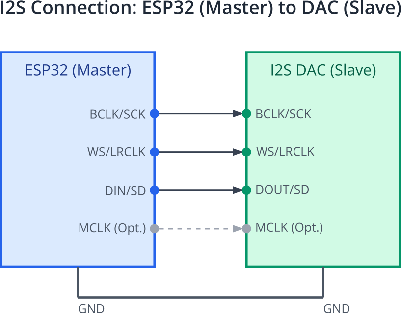
| Master | Generates and outputs SCK. | Generates and outputs WS. | Can transmit (DOUT) and/or receive (DIN) data. Controls timing. | ESP32 controlling an I2S DAC (for audio output) or an I2S ADC (for audio input). ESP32 provides clocks to the codec/converter. |
| Slave | Receives SCK as input. | Receives WS as input. | Can transmit (DOUT) and/or receive (DIN) data. Synchronizes to master’s clocks. | ESP32 receiving audio from another microcontroller or a specialized audio processor that acts as the I2S master. ESP32 could also transmit data as a slave if prompted by master’s clocks. |
Clocking and Sample Rates
The I2S clocks are derived from a source clock, often a PLL (Phase-Locked Loop) within the ESP32. The ESP-IDF driver simplifies clock configuration, allowing you to specify the desired sample rate (e.g., 8kHz, 16kHz, 44.1kHz, 48kHz) and bits per sample.
sample_rate: The number of audio samples per second for each channel.bits_per_sample: The resolution of each audio sample (e.g., 16-bit, 24-bit, 32-bit). Note that the actual data bits might be fewer than the slot bits (e.g., 24-bit data in a 32-bit slot).
The ESP32’s I2S peripheral can use the APLL (Audio PLL) or other PLLs as a high-accuracy clock source, which is crucial for achieving standard audio sample rates with low error.
DMA (Direct Memory Access)
Continuous audio streaming requires transferring large amounts of data at precise intervals. If the CPU were to handle every data byte transfer, it would be heavily burdened, leaving little time for other tasks. This is where DMA comes in.
What is DMA?
DMA is a hardware feature that allows peripherals (like I2S) to access system memory (RAM) directly, without involving the CPU for every byte or word transfer. The CPU initiates a DMA transfer by providing the DMA controller with the source address, destination address, and amount of data to transfer. The DMA controller then handles the data movement, freeing up the CPU.
The ESP32’s I2S peripherals are tightly integrated with its DMA controllers. When transmitting audio, data is written to DMA buffers in memory, and the I2S peripheral fetches it via DMA. When receiving, the I2S peripheral writes incoming audio data to DMA buffers via DMA. This allows for smooth, uninterrupted audio playback and recording. The ESP-IDF I2S driver manages these DMA buffers.
graph LR
    subgraph "CPU / Application"
        A1["CPU (via I2S Driver)<br>Initiates TX"]
        A2["Application writes audio data<br>to TX DMA Buffer in RAM"]
        A3["CPU (via I2S Driver)<br>Initiates RX"]
        A4["Application reads audio data<br>from RX DMA Buffer in RAM"]
    end

    subgraph "DMA Controller & I2S Peripheral"
        B_RAM["RAM<br>(DMA Buffers)"]
        C_DMAC["DMA Controller (DMAC)"]
        D_I2S["I2S Peripheral Hardware"]
        E_External["External I2S Device<br>(e.g., DAC/ADC/Codec)"]
    end

    %% TX Path
    A1 -->|1- Configure DMA for TX| C_DMAC
    A2 -.->|Data| B_RAM
    C_DMAC -->|2- Reads data from RAM TX Buffer| B_RAM
    C_DMAC -->|3- Writes data to I2S TX FIFO| D_I2S
    D_I2S -->|4- Serializes data to External Device| E_External
    C_DMAC -.->|Interrupt on completion/error| A1

    %% RX Path
    A3 -->|1- Configure DMA for RX| C_DMAC
    E_External -->|2- Sends Serialized Audio Data| D_I2S
    D_I2S -->|3- I2S RX FIFO receives data| C_DMAC
    C_DMAC -->|4- Writes data to RAM RX Buffer| B_RAM
    B_RAM -.->|Data available| A4
    C_DMAC -.->|Interrupt on completion/error| A3

    classDef cpu fill:#FEF3C7,stroke:#D97706,stroke-width:1.5px,color:#92400E
    classDef dma fill:#EDE9FE,stroke:#5B21B6,stroke-width:1.5px,color:#5B21B6
    classDef ram fill:#E0F2FE,stroke:#3B82F6,stroke-width:1.5px,color:#1E40AF
    classDef i2speri fill:#D1FAE5,stroke:#059669,stroke-width:1.5px,color:#065F46
    classDef external fill:#F3F4F6,stroke:#6B7280,stroke-width:1.5px,color:#4B5563

    class A1,A2,A3,A4 cpu
    class B_RAM ram
    class C_DMAC dma
    class D_I2S i2speri
    class E_External external
ESP-IDF I2S Driver (v5.x)
ESP-IDF v5.x introduced a refactored I2S driver that is more flexible and feature-rich compared to legacy versions. The new driver is organized into common components and mode-specific components (Standard, PDM, TDM).
Key header files for standard I2S mode:
driver/i2s_common.h: Common definitions, channel allocation functions.driver/i2s_std.h: Standard I2S mode (Philips, MSB/LSB-justified) specific functions and structures.
Core Concepts in the New Driver:
- Channel Allocation: I2S communication is managed through channels. You first allocate an I2S channel handle (
i2s_chan_handle_t) specifying the I2S port number (e.g.,I2S_NUM_0) and the role (master/slave, tx/rx).i2s_chan_config_t: Configuration for channel allocation (I2S port, role, DMA buffer size).i2s_new_channel(): Function to allocate a new channel.
- Mode Initialization: After allocating a channel, you initialize it for a specific I2S mode (e.g., standard mode).
i2s_std_config_t: Configuration for standard I2S mode. This structure is crucial and includes:clk_cfg: Clock configuration (sample rate, clock source, MCLK multiple). UseI2S_STD_CLK_DEFAULT_CONFIG(sample_rate)for typical settings.slot_cfg: Slot configuration (data bit width, slot bit width, mono/stereo, slot mask). UseI2S_STD_PHILIPS_SLOT_DEFAULT_CONFIG(bits_per_sample, chan_fmt)for Philips standard.gpio_cfg: GPIO pin configuration for BCLK, WS, DOUT, DIN, and MCLK.
i2s_channel_init_std_mode(): Initializes the allocated channel for standard I2S communication.
- Channel Control:
i2s_channel_enable(): Enables the channel to start clock generation and data transfer.i2s_channel_disable(): Disables the channel.i2s_channel_write(): Writes data to the TX channel (for playback).i2s_channel_read(): Reads data from the RX channel (for recording).i2s_del_channel(): Deallocates the channel and releases resources.
I2S Modes in ESP-IDF:
While this chapter focuses on Standard I2S mode (including Philips, MSB-justified, LSB-justified), the ESP32 I2S peripheral and its driver also support:
- PDM (Pulse Density Modulation) Mode: Used with PDM digital microphones. Typically involves higher clock rates and decimation filters. (See
driver/i2s_pdm.h) - TDM (Time Division Multiplexing) Mode: Allows multiple audio channels over a single data line by dividing the frame into more time slots. (See
driver/i2s_tdm.h)
These specialized modes will be covered in more detail in subsequent chapters where relevant (e.g., Chapter 139 for PDM microphones).
| I2S Mode | Description | Typical Use Case / Components | Key ESP-IDF Header(s) | Initialization Function Example |
|---|---|---|---|---|
| Standard Mode | Traditional I2S communication. Supports Philips, MSB-justified, LSB-justified, and PCM (short/long frame) formats. | Interfacing with common I2S DACs (e.g., PCM5102A, MAX98357A), ADCs, and audio codecs. | driver/i2s_common.hdriver/i2s_std.h |
i2s_channel_init_std_mode() |
| PDM (Pulse Density Modulation) Mode | Interface for PDM digital signals, typically from PDM microphones. Involves higher clock rates and requires decimation for PCM conversion. | Digital PDM microphones (e.g., MP34DT01-M, SPH0645LM4H). Driver can handle PDM to PCM conversion. | driver/i2s_common.hdriver/i2s_pdm.h |
i2s_channel_init_pdm_rx_mode() (for RX)i2s_channel_init_pdm_tx_mode() (for TX, less common) |
| TDM (Time Division Multiplexing) Mode | Allows multiple audio channels (more than stereo) over a single data line by dividing each frame into multiple time slots. | Multi-channel audio systems, audio arrays, interfacing with codecs that support TDM. | driver/i2s_common.hdriver/i2s_tdm.h |
i2s_channel_init_tdm_mode() |
| Built-in DAC Mode (ESP32 original) | Routes I2S0 output directly to the internal 8-bit DACs of the original ESP32. | Simple, low-fidelity audio output without external components on ESP32. | driver/i2s_std.h (configuration)hal/i2s_ll.h (low-level DAC connection) |
i2s_channel_init_std_mode() with specific slot/GPIO config, then i2s_channel_set_dac_mode() or similar internal routing. |
Practical Examples
Let’s explore how to use the I2S peripheral on an ESP32 device. Ensure you have ESP-IDF v5.x correctly set up in your VS Code environment.
Tip: For all examples, you will need to include the relevant I2S headers:
#include "driver/i2s_std.h"
#include "driver/gpio.h" // For gpio_num_t
#include "esp_log.h" // For logging
Example 1: I2S Master – Transmitting Audio (Sine Wave)
This example demonstrates how to configure an ESP32 as an I2S master to transmit a generated sine wave. This is a fundamental step for audio output applications.
Goal: Output a sine wave digitally via the I2S interface. Hardware:
- An ESP32 development board.
- An I2S DAC module (e.g., MAX98357A, PCM5102A, CJMCU-1334 UDA1334A). Connect the ESP32’s I2S pins (BCK, WS, DOUT) to the DAC’s corresponding pins. Also connect GND and VCC.
- Optionally, a logic analyzer to observe the I2S signals or an oscilloscope/speaker connected to the DAC output.
Code Snippet (C):
#include <stdio.h>
#include <string.h>
#include <math.h>
#include "freertos/FreeRTOS.h"
#include "freertos/task.h"
#include "driver/i2s_std.h"
#include "driver/gpio.h"
#include "esp_system.h"
#include "esp_log.h"

static const char *TAG = "I2S_EXAMPLE";

// I2S Configuration
#define I2S_EXAMPLE_PORT                (I2S_NUM_0)
#define I2S_EXAMPLE_SAMPLE_RATE         (44100)
#define I2S_EXAMPLE_BITS_PER_SAMPLE     (I2S_DATA_BIT_WIDTH_16BIT)
#define I2S_EXAMPLE_CHANNEL_FORMAT      (I2S_CHANNEL_FMT_RIGHT_LEFT) // Stereo

// I2S Pins - Modify these based on your ESP32 board and DAC connections
#define I2S_EXAMPLE_PIN_BCK             (GPIO_NUM_26) // Bit Clock
#define I2S_EXAMPLE_PIN_WS              (GPIO_NUM_25) // Word Select (L/R Clock)
#define I2S_EXAMPLE_PIN_DOUT            (GPIO_NUM_22) // Data Out
#define I2S_EXAMPLE_PIN_DIN             (I2S_GPIO_UNUSED) // Data In (not used for TX)
#define I2S_EXAMPLE_PIN_MCK             (I2S_GPIO_UNUSED) // Master Clock (not used by some DACs like MAX98357A)


// Sine wave generation parameters
#define SINE_WAVE_FREQUENCY             (440) // A4 note, 440 Hz
#define AMPLITUDE                       (INT16_MAX / 2) // Max amplitude for 16-bit signed audio
#define BUFFER_SIZE_BYTES               (1024) // Size of buffer to send to I2S

static i2s_chan_handle_t tx_chan; // I2S TX channel handle

void i2s_example_init_tx(void) {
    ESP_LOGI(TAG, "Initializing I2S TX channel...");

    // 1. Allocate a new TX channel
    i2s_chan_config_t tx_chan_cfg = I2S_CHANNEL_DEFAULT_CONFIG(I2S_EXAMPLE_PORT, I2S_ROLE_MASTER);
    tx_chan_cfg.dma_desc_num = 4; // Number of DMA descriptors
    tx_chan_cfg.dma_frame_num = 256; // DMA frame size (in samples)
    tx_chan_cfg.auto_clear = true; // Auto clear TX DMA buffer on stop

    ESP_ERROR_CHECK(i2s_new_channel(&tx_chan_cfg, &tx_chan, NULL));

    // 2. Configure standard I2S mode
    i2s_std_config_t tx_std_cfg = {
        .clk_cfg = I2S_STD_CLK_DEFAULT_CONFIG(I2S_EXAMPLE_SAMPLE_RATE),
        .slot_cfg = I2S_STD_PHILIPS_SLOT_DEFAULT_CONFIG(I2S_EXAMPLE_BITS_PER_SAMPLE, I2S_EXAMPLE_CHANNEL_FORMAT),
        .gpio_cfg = {
            .mclk = I2S_EXAMPLE_PIN_MCK,
            .bclk = I2S_EXAMPLE_PIN_BCK,
            .ws = I2S_EXAMPLE_PIN_WS,
            .dout = I2S_EXAMPLE_PIN_DOUT,
            .din = I2S_EXAMPLE_PIN_DIN, // Not used
            .invert_flags = {
                .mclk_inv = false,
                .bclk_inv = false,
                .ws_inv = false,
            },
        },
    };
    // For some DACs, MCLK might not be needed or might have specific requirements
    // If MCLK is used, tx_std_cfg.clk_cfg.mclk_multiple may need adjustment.
    // tx_std_cfg.clk_cfg.clk_src = I2S_CLK_SRC_APLL; // Or I2S_CLK_SRC_DEFAULT for XTAL/PLL_F160M etc.

    ESP_ERROR_CHECK(i2s_channel_init_std_mode(tx_chan, &tx_std_cfg));

    // 3. Enable the TX channel
    ESP_ERROR_CHECK(i2s_channel_enable(tx_chan));
    ESP_LOGI(TAG, "I2S TX channel initialized and enabled.");
}

void i2s_example_write_sine_wave(void) {
    uint8_t *tx_buffer = (uint8_t *)malloc(BUFFER_SIZE_BYTES);
    if (!tx_buffer) {
        ESP_LOGE(TAG, "Failed to allocate memory for TX buffer");
        return;
    }

    ESP_LOGI(TAG, "Starting sine wave output...");
    size_t bytes_written = 0;
    int16_t sample_val;
    double time_step = 1.0 / I2S_EXAMPLE_SAMPLE_RATE;
    double current_time = 0;

    while (1) {
        for (int i = 0; i < BUFFER_SIZE_BYTES / (I2S_EXAMPLE_BITS_PER_SAMPLE / 8 * 2); i++) { // 2 channels
            sample_val = (int16_t)(AMPLITUDE * sin(2 * M_PI * SINE_WAVE_FREQUENCY * current_time));

            // Stereo: Write same sample to Left and Right channels for simplicity
            // Assuming 16-bit samples
            tx_buffer[i * 4 + 0] = sample_val & 0xFF;         // Left LSB
            tx_buffer[i * 4 + 1] = (sample_val >> 8) & 0xFF;  // Left MSB
            tx_buffer[i * 4 + 2] = sample_val & 0xFF;         // Right LSB
            tx_buffer[i * 4 + 3] = (sample_val >> 8) & 0xFF;  // Right MSB

            current_time += time_step;
        }

        esp_err_t ret = i2s_channel_write(tx_chan, tx_buffer, BUFFER_SIZE_BYTES, &bytes_written, portMAX_DELAY);
        if (ret != ESP_OK) {
            ESP_LOGE(TAG, "I2S write error: %s", esp_err_to_name(ret));
        } else if (bytes_written < BUFFER_SIZE_BYTES) {
            ESP_LOGW(TAG, "I2S write underrun: wrote %d of %d bytes", bytes_written, BUFFER_SIZE_BYTES);
        }
        // No need for vTaskDelay if i2s_channel_write blocks sufficiently.
        // If it returns too quickly and overloads CPU, add a small delay.
        // vTaskDelay(pdMS_TO_TICKS(1));
    }
    // This part is unreachable in the current loop, but good practice for cleanup
    // free(tx_buffer);
    // i2s_channel_disable(tx_chan);
    // i2s_del_channel(tx_chan);
}

void app_main(void) {
    i2s_example_init_tx();
    xTaskCreate( (void (*)(void*)) i2s_example_write_sine_wave, "i2s_sine_task", 4096, NULL, 5, NULL);
}
Build Instructions:
- Save the code as
main.cin themaindirectory of a new ESP-IDF project. - Ensure your
CMakeLists.txtin themaindirectory includesidf_component_register(SRCS "main.c" INCLUDE_DIRS "."). - Open VS Code, ensure the Espressif IDF Extension is active and configured for your ESP32 variant and ESP-IDF v5.x.
- Use the “ESP-IDF: Build your project” command.
Run/Flash/Observe:
- Connect your ESP32 board to your computer.
- Connect the I2S DAC to the specified GPIO pins.
- Use the “ESP-IDF: Flash your project” command.
- If a speaker is connected to the DAC, you should hear a tone.
- If using a logic analyzer, observe the BCK, WS, and DOUT signals. BCK should be
I2S_EXAMPLE_SAMPLE_RATE * I2S_EXAMPLE_BITS_PER_SAMPLE * num_channels(e.g., 44100 * 16 * 2 = 1.4112 MHz). WS should beI2S_EXAMPLE_SAMPLE_RATE(44.1 kHz). DOUT will show the serialized sine wave data.
Warning: Always double-check your wiring before powering on. Incorrect connections can damage your ESP32 or DAC.
Example 2: I2S Slave – Receiving Audio (Conceptual Setup)
This example outlines the configuration for an ESP32 to act as an I2S slave, receiving audio data from an external I2S master. A full working example requires an external I2S master source (e.g., another microcontroller or a specialized I2S audio IC).
Goal: Configure ESP32 as an I2S slave to read incoming audio data. Hardware:
- An ESP32 development board.
- An I2S master device providing BCK, WS, and SD (connected to ESP32’s DIN).
Code Snippet (C – Configuration and Reading Loop):
#include <stdio.h>
#include <string.h>
#include "freertos/FreeRTOS.h"
#include "freertos/task.h"
#include "driver/i2s_std.h"
#include "driver/gpio.h"
#include "esp_system.h"
#include "esp_log.h"

static const char *TAG_RX = "I2S_RX_EXAMPLE";

// I2S Configuration (Slave Mode)
#define I2S_RX_EXAMPLE_PORT             (I2S_NUM_1) // Use a different port if available and needed
#define I2S_RX_EXAMPLE_SAMPLE_RATE      (16000)     // Must match master's sample rate
#define I2S_RX_EXAMPLE_BITS_PER_SAMPLE  (I2S_DATA_BIT_WIDTH_16BIT) // Must match master
#define I2S_RX_EXAMPLE_CHANNEL_FORMAT   (I2S_CHANNEL_FMT_ONLY_LEFT) // Or stereo, must match master

// I2S Pins - Modify these based on your ESP32 board and master connections
#define I2S_RX_EXAMPLE_PIN_BCK          (GPIO_NUM_5)  // Bit Clock (Input from Master)
#define I2S_RX_EXAMPLE_PIN_WS           (GPIO_NUM_18) // Word Select (Input from Master)
#define I2S_RX_EXAMPLE_PIN_DOUT         (I2S_GPIO_UNUSED) // Data Out (not used for RX)
#define I2S_RX_EXAMPLE_PIN_DIN          (GPIO_NUM_19) // Data In (Input from Master)
#define I2S_RX_EXAMPLE_PIN_MCK          (I2S_GPIO_UNUSED) // Master Clock (usually not needed for slave if master provides all clocks)

#define RX_BUFFER_SIZE_BYTES            (1024)

static i2s_chan_handle_t rx_chan; // I2S RX channel handle

void i2s_example_init_rx(void) {
    ESP_LOGI(TAG_RX, "Initializing I2S RX channel (Slave Mode)...");

    // 1. Allocate a new RX channel
    i2s_chan_config_t rx_chan_cfg = I2S_CHANNEL_DEFAULT_CONFIG(I2S_RX_EXAMPLE_PORT, I2S_ROLE_SLAVE);
    rx_chan_cfg.dma_desc_num = 4;
    rx_chan_cfg.dma_frame_num = 256;

    ESP_ERROR_CHECK(i2s_new_channel(&rx_chan_cfg, NULL, &rx_chan)); // Note: &rx_chan is the last param for RX

    // 2. Configure standard I2S mode for slave
    i2s_std_config_t rx_std_cfg = {
        // Clock config for slave is mainly for configuring the expected format,
        // as the actual clocks are driven by the master.
        // Sample rate here should match what the master will provide.
        .clk_cfg = I2S_STD_CLK_DEFAULT_CONFIG(I2S_RX_EXAMPLE_SAMPLE_RATE),
        .slot_cfg = I2S_STD_PHILIPS_SLOT_DEFAULT_CONFIG(I2S_RX_EXAMPLE_BITS_PER_SAMPLE, I2S_RX_EXAMPLE_CHANNEL_FORMAT),
        .gpio_cfg = {
            .mclk = I2S_RX_EXAMPLE_PIN_MCK,
            .bclk = I2S_RX_EXAMPLE_PIN_BCK,
            .ws = I2S_RX_EXAMPLE_PIN_WS,
            .dout = I2S_RX_EXAMPLE_PIN_DOUT, // Not used for RX
            .din = I2S_RX_EXAMPLE_PIN_DIN,
            .invert_flags = {
                .mclk_inv = false,
                .bclk_inv = false,
                .ws_inv = false,
            },
        },
    };
    // For slave mode, clk_src is typically ignored as clocks come from master.
    // tx_std_cfg.clk_cfg.clk_src = I2S_CLK_SRC_EXTERNAL; // This might be implicit for slave.

    ESP_ERROR_CHECK(i2s_channel_init_std_mode(rx_chan, &rx_std_cfg));

    // 3. Enable the RX channel
    ESP_ERROR_CHECK(i2s_channel_enable(rx_chan));
    ESP_LOGI(TAG_RX, "I2S RX channel initialized and enabled.");
}

void i2s_example_read_data(void) {
    uint8_t *rx_buffer = (uint8_t *)malloc(RX_BUFFER_SIZE_BYTES);
    if (!rx_buffer) {
        ESP_LOGE(TAG_RX, "Failed to allocate memory for RX buffer");
        return;
    }

    ESP_LOGI(TAG_RX, "Starting to read I2S data...");
    size_t bytes_read = 0;

    while (1) {
        esp_err_t ret = i2s_channel_read(rx_chan, rx_buffer, RX_BUFFER_SIZE_BYTES, &bytes_read, portMAX_DELAY);
        if (ret != ESP_OK) {
            ESP_LOGE(TAG_RX, "I2S read error: %s", esp_err_to_name(ret));
        } else if (bytes_read == 0) {
            ESP_LOGW(TAG_RX, "I2S read timeout or no data.");
        } else {
            ESP_LOGI(TAG_RX, "Read %d bytes:", bytes_read);
            // Process the received data in rx_buffer
            // For 16-bit mono, each sample is 2 bytes.
            // Example: Print first few samples
            for(int i=0; i < bytes_read && i < 16; i+=2) {
                int16_t sample = (rx_buffer[i+1] << 8) | rx_buffer[i];
                printf("%d ", sample);
            }
            printf("\n");
        }
    }
    // This part is unreachable in the current loop
    // free(rx_buffer);
    // i2s_channel_disable(rx_chan);
    // i2s_del_channel(rx_chan);
}

void app_main(void) {
    // This example assumes an external I2S master is providing data.
    i2s_example_init_rx();
    xTaskCreate( (void (*)(void*)) i2s_example_read_data, "i2s_read_task", 4096, NULL, 5, NULL);
}
Build and Run: Follow similar build and flash steps as Example 1. When running, the ESP32 will wait for an I2S master to provide clock signals and data on the configured pins. The received data (if any) will be logged to the serial monitor.
Tip: When configuring slave mode, ensure the
sample_rate,bits_per_sample, andchannel_formatini2s_std_config_tprecisely match the characteristics of the incoming I2S signal from the master.
Variant Notes
The ESP32 family includes several variants, and their I2S capabilities can differ slightly. However, the ESP-IDF I2S driver API aims to provide a consistent interface.
- Number of I2S Controllers:
- ESP32: 2 I2S controllers (I2S0, I2S1). This allows for simultaneous input and output, or two independent I2S interfaces.
- ESP32-S2: 1 I2S controller (I2S0).
- ESP32-S3: 2 I2S controllers (I2S0, I2S1).
- ESP32-C3: 1 I2S controller (I2S0).
- ESP32-C6: 1 I2S controller (I2S0).
- ESP32-H2: 1 I2S controller (I2S0). You select the controller using the
i2s_port_targument (e.g.,I2S_NUM_0,I2S_NUM_1) ini2s_chan_config_t.I2S_NUM_AUTOcan also be used to let the driver pick an available port.
- GPIO Matrix and Pin Assignment: All modern ESP32 variants feature a flexible GPIO matrix, allowing most I2S signals to be routed to various GPIO pins. However, always consult the specific variant’s datasheet for any pin restrictions (e.g., some pins might be input-only, strapping pins, or have preferred peripheral functions). The
gpio_cfgwithini2s_std_config_tis used to assign these pins. - Clock Sources (APLL/PLL): Most ESP32 variants include an Audio PLL (APLL) or other suitable PLLs that can generate accurate clock frequencies for standard audio sample rates. The
i2s_std_clk_config_tstructure’sclk_srcfield (e.g.,I2S_CLK_SRC_DEFAULT,I2S_CLK_SRC_APLL) allows selecting the clock source. The availability and specific PLLs might differ slightly between variants, butI2S_CLK_SRC_DEFAULTusually picks a suitable one. For very precise audio applications, explicitly using APLL might be beneficial if available. - Supported I2S Modes (Standard, PDM, TDM):
- All listed variants (ESP32, S2, S3, C3, C6, H2) generally support Standard I2S, PDM input (for digital microphones), and TDM modes through their I2S controllers and the ESP-IDF driver. The new driver architecture with
i2s_std.h,i2s_pdm.h, andi2s_tdm.hcaters to these modes.
- All listed variants (ESP32, S2, S3, C3, C6, H2) generally support Standard I2S, PDM input (for digital microphones), and TDM modes through their I2S controllers and the ESP-IDF driver. The new driver architecture with
- Internal DAC/ADC Connection:
- ESP32 (original): The I2S peripheral (specifically I2S0) can be internally routed to the built-in 8-bit DACs for direct audio output without an external I2S DAC. It can also be connected to the ADC. This is done using dedicated functions like
i2s_set_dac_mode()(legacy API) or by configuring the I2S driver for DAC/ADC mode (check current v5.x API fori2s_dac_audio_mode_enableor similar if using built-in DAC with I2S). Quality is limited by the 8-bit DACs. - Other Variants (S2, S3, C3, C6, H2): Direct connection to internal DACs via I2S might be different or not as straightforward. ESP32-S2 and later chips often focus on external I2S codecs for audio. Always refer to the Technical Reference Manual (TRM) for the specific variant regarding internal DAC/ADC connections with I2S. The primary use case for I2S is interfacing with external, higher-fidelity audio components.
- ESP32 (original): The I2S peripheral (specifically I2S0) can be internally routed to the built-in 8-bit DACs for direct audio output without an external I2S DAC. It can also be connected to the ADC. This is done using dedicated functions like
- LCD Mode / Camera Mode: Some ESP32 I2S peripherals (especially on ESP32 original and S3) have an “LCD mode” or “camera mode” where the I2S hardware can be repurposed for parallel data transmission, often used for camera interfaces or simple parallel LCDs. This is an advanced use of the I2S peripheral and is distinct from its audio functionality.
Recommendation: Always consult the latest ESP-IDF documentation and the Technical Reference Manual for your specific ESP32 variant to understand the precise capabilities and any limitations of its I2S interface.
Common Mistakes & Troubleshooting Tips
| Mistake / Issue | Symptom(s) | Troubleshooting / Solution |
|---|---|---|
Incorrect Pin Configuration (gpio_cfg) |
No audio, distorted audio, no clock/data signals observed on logic analyzer. | Verify GPIO numbers for BCK, WS, DOUT, DIN, MCLK. Ensure physical wiring matches configuration. Check for pin conflicts. Use I2S_GPIO_UNUSED for unused pins. |
| Clock/Format Mismatch | Distorted audio, noise, incorrect speed, one channel silent. Master/slave or ESP32/codec settings differ. | Ensure sample_rate, bits_per_sample, slot_cfg (format, e.g., Philips, LJ, RJ), and channel_fmt (mono/stereo) match between all I2S devices. Check invert_flags. Refer to codec datasheet. |
| DMA Buffer Issues | Audio glitches (clicks, pops), stuttering, underruns (TX)/overruns (RX). ESP_ERR_TIMEOUT from write/read. |
Adjust dma_desc_num and dma_frame_num in i2s_chan_config_t. Larger buffers can help but increase latency. Ensure CPU can service DMA buffers in time. |
| I2S Channel Not Enabled / Incorrect Setup Order | No audio output/input. I2S functions return errors. | Ensure correct sequence: i2s_new_channel() -> i2s_channel_init_std_mode() (or other mode) -> i2s_channel_enable(). Check all return codes. |
| MCLK Configuration Problems (if used) | Codec not working, no audio, or distorted audio if codec requires MCLK. | Verify codec MCLK requirements (frequency, e.g., 256*Fs). Ensure MCLK pin in gpio_cfg is correct and wired. Set clk_cfg.mclk_multiple appropriately. If codec generates MCLK or doesn’t need it, set pin to I2S_GPIO_UNUSED. |
| Data Type Mismatch / Endianness | Audio sounds noisy, distorted, or at wrong pitch/amplitude. | Ensure data written to i2s_channel_write() (or read from i2s_channel_read()) matches configured bits_per_sample and endianness expected by I2S peripheral/codec (usually MSB first). E.g., for 16-bit, send int16_t samples. |
| Task Stack Overflow for I2S Task | Crashes, unexpected behavior, especially if processing audio or logging heavily in the I2S task. | Increase stack size for the task calling I2S read/write functions in xTaskCreate(). |
| Power Supply Issues for DAC/Codec | No audio, distorted audio, DAC/codec not initializing. | Ensure the external I2S device has a stable and correct power supply (voltage and current). Check for proper grounding. |
Exercises
- Square Wave Output:
- Modify Example 1 (
i2s_example_write_sine_wave) to output a square wave instead of a sine wave. A square wave can be generated by alternating betweenAMPLITUDEand-AMPLITUDEvalues for a certain number of samples. Observe the output on a logic analyzer or, if using a DAC and speaker, listen to the different timbre.
- Modify Example 1 (
- Sample Rate and Bit Depth Variation:
- Take Example 1 and configure the I2S transmitter for different standard sample rates (e.g., 8000 Hz, 16000 Hz, 32000 Hz, 48000 Hz) and bit depths (e.g.,
I2S_DATA_BIT_WIDTH_24BIT,I2S_DATA_BIT_WIDTH_32BIT, if your DAC supports it). - Verify the WS and BCLK frequencies using a logic analyzer. For BCLK, remember
BCLK_freq = sample_rate * num_channels * bits_per_sample_in_slot. - Note: If changing
bits_per_sample, ensure your data generation and DAC can handle it. For 24/32 bit, you’ll need to pack more bytes per sample.
- Take Example 1 and configure the I2S transmitter for different standard sample rates (e.g., 8000 Hz, 16000 Hz, 32000 Hz, 48000 Hz) and bit depths (e.g.,
- I2S Loopback Test:
- If your ESP32 variant has two I2S controllers (e.g., ESP32, ESP32-S3):
- Configure I2S0 as a master transmitter (similar to Example 1).
- Configure I2S1 as a slave receiver (similar to Example 2).
- Physically connect the DOUT pin of I2S0 to the DIN pin of I2S1. Also connect BCK and WS from I2S0 to I2S1.
- Transmit known data (e.g., a sequence of numbers) from I2S0 and verify that I2S1 receives the same data.
- If your ESP32 variant has only one I2S controller (e.g., ESP32-S2, C3, C6, H2):
- This exercise is more challenging. You can conceptually describe the setup or, if you have an external I2S device that can echo data, use that. A simple hardware loopback (DOUT to DIN on the same controller) is generally not feasible for standard I2S operation as it requires the controller to be master TX and slave RX simultaneously on the same data line with shared clocks, which the hardware might not support in a straightforward way for standard mode.
- Alternative Task: Research and describe how you would test I2S receive functionality on a single-controller ESP32 using an external I2S signal generator or another microcontroller as a master.
- If your ESP32 variant has two I2S controllers (e.g., ESP32, ESP32-S3):
- Stereo Panning Effect:
- Modify Example 1 (sine wave output) to create a simple stereo panning effect. Instead of sending the exact same sample to both left and right channels, vary their amplitudes. For example, make the left channel louder for a second, then the right channel louder for a second, and alternate.
tx_buffer[i * 4 + 0]andtx_buffer[i * 4 + 1]are for one channel (e.g., left).tx_buffer[i* 4+ 2]andtx_buffer[i * 4 + 3]are for the other channel (e.g., right).- You’ll need to generate
sample_val_leftandsample_val_rightand pack them accordingly.
Summary
- I2S is a serial protocol for transmitting digital audio data between ICs, using signals like SCK (Bit Clock), WS (Word Select/LR Clock), and SD (Serial Data).
- ESP32 microcontrollers feature built-in I2S peripherals capable of acting in master or slave mode, for transmitting (TX) or receiving (RX) audio.
- The ESP-IDF v5.x provides a comprehensive I2S driver (
driver/i2s_common.h,driver/i2s_std.h, etc.) for configuring and managing I2S communication. - Key configuration steps involve:
- Allocating an I2S channel (
i2s_new_channel) with role (master/slave, tx/rx) and DMA settings. - Initializing the channel for a specific mode (e.g., standard I2S using
i2s_channel_init_std_mode) with clock, slot, and GPIO pin configurations. - Enabling the channel (
i2s_channel_enable) to start operation. - Using
i2s_channel_write()for transmitting ori2s_channel_read()for receiving data.
- Allocating an I2S channel (
- DMA is crucial for efficient, continuous audio data streaming without high CPU overhead.
- Different ESP32 variants offer one or two I2S controllers, but the ESP-IDF driver provides a largely consistent API. Always check the variant’s TRM for specifics.
- Common issues often relate to incorrect pin assignments, clock/format mismatches, or DMA buffer sizing.
Further Reading
- ESP-IDF Programming Guide – I2S:
- For the latest ESP-IDF v5.x: https://docs.espressif.com/projects/esp-idf/en/v5.2.1/esp32/api-reference/peripherals/i2s.html
- ESP32 Series Technical Reference Manuals:
- Available from the Espressif website: https://www.espressif.com/en/support/documents/technical-documents
- Philips I2S Bus Specification:
- A search for “Philips I2S bus specification PDF” will usually yield original or derivative documents explaining the standard (e.g., “AN4832 I2S bus specification and application hints” by NXP).
- Datasheets for I2S Codecs/DACs/ADCs

Excellent lesson on ESP32 I2S!!