
Chapter 140: I2S Audio Codec Integration with ESP-IDF
Chapter Objectives
By the end of this chapter, you will be able to:
- Understand the role, architecture, and benefits of audio codecs in embedded systems.
- Learn about common communication interfaces for audio codecs, specifically I2S for audio data and I2C for control.
- Configure the ESP32 I2S peripheral for bi-directional communication with an audio codec.
- Initialize and control a typical audio codec by writing to and reading from its registers using the ESP32 I2C master driver.
- Implement practical examples for audio playback (output) and recording (input) through an external audio codec.
- Be aware of differences and considerations when interfacing codecs with various ESP32 variants.
- Identify common issues and apply troubleshooting techniques for audio codec integration.
Introduction
In the preceding chapters, we’ve explored the I2S protocol for basic digital audio transfer (Chapter 138) and the integration of digital microphones (Chapter 139). While these provide foundational audio capabilities, many applications demand higher fidelity, more complex audio routing, amplification, and signal processing. This is where dedicated audio codecs come into play.
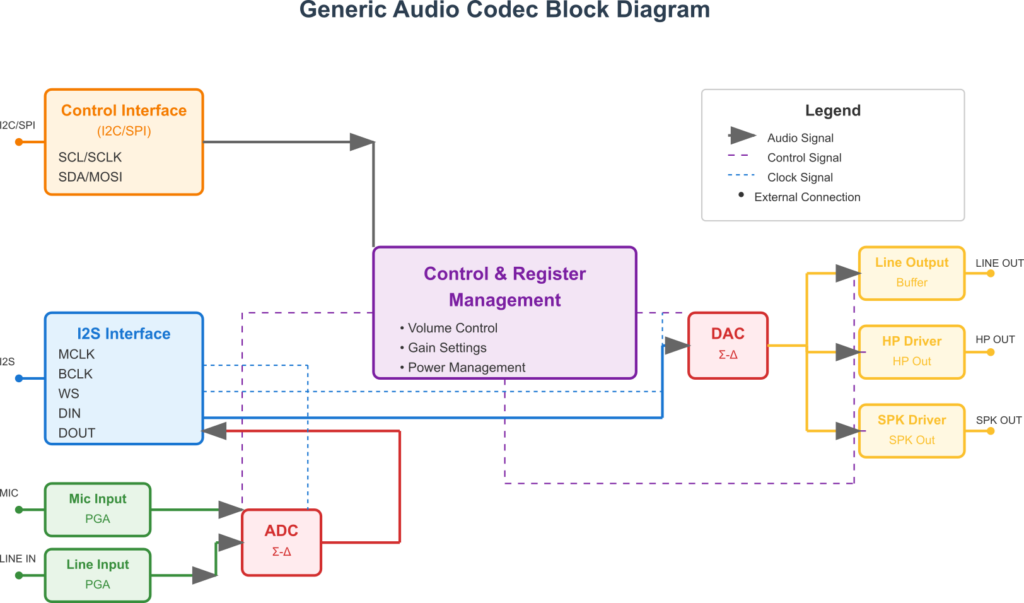
An audio COder-DECoder (codec) is an integrated circuit that typically combines Analog-to-Digital Converters (ADCs), Digital-to-Analog Converters (DACs), amplifiers, mixers, and various audio processing blocks into a single chip. They serve as a bridge between the analog audio world (microphones, speakers, line-level signals) and the digital domain of microcontrollers like the ESP32.
This chapter will guide you through the process of integrating an external audio codec with an ESP32. We will focus on using the I2S interface for transferring audio data and the I2C interface for configuring and controlling the codec. Mastering codec integration unlocks the potential for developing sophisticated audio applications, such as high-quality music players, voice recorders, intercom systems, and voice-controlled devices with significantly improved audio performance.
Theory
What is an Audio Codec?
An audio codec is a specialized mixed-signal integrated circuit designed to handle a wide range of audio tasks. The term “codec” signifies its dual role:
- Coder (Encoder): Converts analog audio signals into digital audio data (PCM samples) using an ADC. This is used for recording or capturing audio.
- Decoder: Converts digital audio data (PCM samples) back into analog audio signals using a DAC. This is used for playback.
Beyond basic ADC and DAC functions, modern audio codecs often integrate a plethora of features:
| Feature Category | Specific Functions / Components | Benefit / Purpose |
|---|---|---|
| Analog-to-Digital Conversion (ADC) | ADC core, Input Multiplexer (MUX), Preamplifiers, Programmable Gain Amplifiers (PGA) | Converts analog audio (mic, line-in) to digital PCM data for processing/recording. Gain control optimizes input levels. |
| Digital-to-Analog Conversion (DAC) | DAC core, Output Mixers, Volume Control | Converts digital PCM audio data to analog signals for playback. |
| Output Drivers | Headphone Amplifiers, Line Output Drivers, Speaker Amplifiers (e.g., Class-D) | Directly drive headphones, line-level outputs, or small speakers, reducing external component needs. |
| Input Conditioning | Microphone Bias Voltage, Input PGAs, Anti-aliasing Filters | Powers microphones, adjusts input signal strength, prevents aliasing during ADC. |
| Audio Processing | Digital Volume Control, Mixers, Equalizers (EQ), Tone Controls, Automatic Gain Control (AGC), Dynamic Range Compression (DRC), Sidetone Paths | Enhances audio quality, manages levels, allows signal routing and effects, often offloading these tasks from the MCU. |
| Clock Management | Internal PLLs (Phase-Locked Loops), Clock Dividers, MCLK Input/Output options | Generates or synchronizes to various clock frequencies required for different sample rates and internal operations. Can reduce need for precise external MCLK. |
| Power Management | Selective power-down of internal blocks (ADC, DAC, amplifiers, etc.), low-power modes | Optimizes power consumption, crucial for battery-operated devices. |
| Control Interface | I2C or SPI slave interface, Register Map | Allows the host MCU (e.g., ESP32) to configure and control all codec functions by writing to/reading from internal registers. |
- Preamplifiers: For microphone (Mic In) and line-level (Line In) analog inputs.
- Programmable Gain Amplifiers (PGAs): To adjust input and output signal levels digitally.
- Headphone Drivers: To directly drive headphones.
- Speaker Drivers: Sometimes included to directly drive small speakers (often Class-D amplifiers).
- Microphone Bias Voltage: To power electret condenser microphones.
- Audio Mixers: To combine multiple audio sources or route signals internally.
- Volume Control: Digital and sometimes analog volume adjustment.
- Equalization (EQ) and Tone Control: To shape the frequency response.
- Automatic Gain Control (AGC) / Dynamic Range Compression (DRC): To manage varying input levels.
- Power Management: Sophisticated control over which internal blocks are powered to save energy.
- Clock Generation/Management: Often include PLLs to generate necessary internal clocks from a master clock (MCLK).
Why Use a Codec?
While the ESP32 (original variant) has built-in DACs and ADCs, and we’ve seen how to use digital microphones, external audio codecs offer significant advantages for more demanding audio applications:
- Superior Audio Quality: Codecs are optimized for audio and typically provide much higher Signal-to-Noise Ratios (SNR), lower Total Harmonic Distortion (THD), and better dynamic range than general-purpose MCUs’ internal converters. They often support higher bit depths (e.g., 24-bit, 32-bit) and sample rates.
- Integrated Analog Front-End: They consolidate preamplifiers, biasing, and impedance matching, reducing the need for many external analog components and simplifying PCB design.
- Output Driving Capability: Integrated headphone and speaker drivers can directly power transducers without requiring additional external amplifier ICs for many use cases.
- Advanced Audio Features: Features like hardware mixing, equalization, and AGC can offload processing from the MCU.
- Reduced System Noise: Separating sensitive analog audio circuitry onto a dedicated codec IC can help isolate it from the digital noise generated by the MCU and other peripherals.
- Power Efficiency: Codecs often have fine-grained power control for their internal blocks, allowing for optimized power consumption in battery-operated devices.
Communication with Audio Codecs
Interfacing with an audio codec typically involves two distinct communication paths:
| Interface Type | Protocol | Purpose | ESP32 Role | Codec Role | Key Signals (ESP32 to Codec) |
|---|---|---|---|---|---|
| Audio Data Path | I2S (Inter-IC Sound) | Transferring digital audio samples (PCM data) between ESP32 and codec. | Master (typically) | Slave (typically) | BCLK (Bit Clock), WS (Word Select/LRCLK), DOUT (Data Out to Codec for playback), DIN (Data In from Codec for recording), MCLK (Master Clock, if required by codec). |
| Control Path | I2C (Inter-Integrated Circuit) | Configuring codec parameters (volume, sample rate, input/output selection, power modes, etc.) by accessing internal registers. | Master | Slave | SCL (Serial Clock), SDA (Serial Data). Requires pull-up resistors. |
| SPI (Serial Peripheral Interface) | Master | Slave | SCLK (Serial Clock), MOSI (Master Out Slave In), MISO (Master In Slave Out), CS (Chip Select). |
- Audio Data Path (I2S):
- The actual digital audio samples (PCM data) are transferred between the ESP32 and the codec using the I2S protocol.
- The ESP32 usually acts as the I2S Master, providing the Bit Clock (BCLK) and Word Select (WS / LRCLK) signals to the codec (which acts as I2S Slave).
- For playback, the ESP32 sends data on its I2S DOUT (Data Out) pin, connected to the codec’s I2S DIN (Data In) pin.
- For recording, the codec sends data on its I2S DOUT pin, connected to the ESP32’s I2S DIN pin.
- Some codecs also require a Master Clock (MCLK), which can often be supplied by the ESP32’s I2S peripheral. MCLK is typically a multiple of the sample rate (e.g., 128Fs, 256Fs, 512*Fs).
- Control Path (I2C or SPI):
- The codec’s internal functions, modes, and parameters (e.g., volume, sample rate, input/output selection, power states) are configured by writing to and reading from its internal registers.
- This control communication is most commonly done using the I2C (Inter-Integrated Circuit) protocol. Some codecs might use SPI (Serial Peripheral Interface).
- The ESP32 acts as the I2C Master, and the codec acts as the I2C Slave. Each codec has a specific 7-bit I2C slave address defined in its datasheet.
Codec Configuration via Registers
Audio codecs contain a set of internal registers that control their operation. Each register has an address and holds data bits that configure specific settings. The process of initializing and controlling a codec involves:
flowchart TD
    A[Start: Initialize Codec] --> B{Read Codec Datasheet};
    B --> C["ESP32: Initialize I2C Master Interface"];
    C --> D["ESP32: Add Codec as I2C Slave Device (using Codec's I2C Address)"];
    D --> E{"Optional: Software Reset Codec<br>(Write to Reset Register)"};
    E --> F{"Configure Codec Clocks<br>(MCLK, PLLs, Sample Rate via I2C Registers)"};
    F --> G{"Configure I2S Interface Format on Codec<br>(Philips/LJ/RJ, Bit Depth, Master/Slave via I2C)"};
    G --> H{"Configure Analog Paths:<br>- Power up ADC/DAC sections<br>- Select Input (Mic/Line)<br>- Set PGA Gains<br>- Unmute Inputs/Outputs<br>- Set Output Volumes (HP, Line, Spk)"};
    H --> I{"Verify Critical Settings<br>(Optional: Read back key registers via I2C)"};
    I --> J[Codec Configured & Ready for I2S Data];

    %% Styling
    classDef start fill:#EDE9FE,stroke:#5B21B6,stroke-width:2px,color:#5B21B6;
    classDef process fill:#DBEAFE,stroke:#2563EB,stroke-width:1px,color:#1E40AF;
    classDef decision fill:#FEF3C7,stroke:#D97706,stroke-width:1px,color:#92400E;
    classDef critical fill:#FEE2E2,stroke:#DC2626,stroke-width:1px,color:#991B1B;
    classDef endo fill:#D1FAE5,stroke:#059669,stroke-width:2px,color:#065F46;

    class A,J endo;
    class B critical;
    class C,D,E,F,G,H,I process;
- Reading the Datasheet: The codec’s datasheet is paramount. It contains:
- The I2C slave address(es).
- The register map: a list of all registers, their addresses, bit definitions, and default values.
- Recommended initialization sequences.
- Power-up and power-down procedures.
- Clocking requirements.
- I2S format details (Philips, Left/Right Justified, MSB/LSB first, bit delays).
- Typical Configuration Steps (via I2C):
- Reset: Many codecs have a software reset command or register bit.
- Clock Configuration: Setting the expected MCLK frequency (if used), configuring internal PLLs, and selecting the audio sample rate (e.g., 8kHz, 16kHz, 44.1kHz, 48kHz) and data bit depth (e.g., 16-bit, 24-bit).
- I2S Interface Format: Configuring the codec to match the I2S format the ESP32 will use (e.g., Philips standard, I2S_DATA_BIT_WIDTH_16BIT, stereo/mono).
- Analog Path Setup:
- Enabling and configuring ADCs and DACs.
- Selecting input sources (e.g., microphone input, line input).
- Unmuting inputs and outputs.
- Setting input PGA gains.
- Setting output volume levels (for headphones, line out, speakers).
- Power Management: Powering up required analog and digital blocks (e.g., DACs, ADCs, headphone amplifiers) and powering down unused ones.
Tip: Codec initialization sequences can be complex and order-dependent. Always refer to the “Recommended Initialization Sequence” section in the codec’s datasheet.
ESP-IDF I2C Master Driver (ESP-IDF v5.x)
To control the codec, we’ll use the ESP32’s I2C peripheral in master mode. ESP-IDF v5.x introduced a new I2C master driver (driver/i2c_master.h) which is recommended over the legacy driver.
Key Concepts and Functions:
- Bus Initialization:
i2c_master_bus_config_t: Structure to configure I2C bus parameters like SCL/SDA GPIO numbers, clock speed (clk_source,glitch_filter_ns), and interrupt flags.i2c_new_master_bus(): Initializes an I2C master bus and returns a bus handle (i2c_master_bus_handle_t).
- Device Handle Allocation:
- Once the bus is initialized, you add a specific I2C slave device (the codec) to the bus.
i2c_device_config_t: Structure to configure device-specific parameters, primarily the 7-bit slavedevice_addressand the I2C clock speed for this device (scl_speed_hz).i2c_master_bus_add_device(): Adds a device to the bus and returns a device handle (i2c_master_dev_handle_t). This handle is used for all subsequent transactions with that device.
- I2C Transactions (Writing to Codec Registers):
- Codec registers are typically written by sending the register address followed by the data byte(s).
i2c_master_transmit(): Sends data to the I2C slave device.// Example: Write 'data_byte' to 'register_address' of the codec uint8_t write_buf[2] = {register_address, data_byte}; esp_err_t ret = i2c_master_transmit(codec_dev_handle, write_buf, sizeof(write_buf), I2C_MASTER_TIMEOUT_MS);(Note:I2C_MASTER_TIMEOUT_MSshould be defined, e.g.,pdMS_TO_TICKS(1000))
- I2C Transactions (Reading from Codec Registers):
- Reading often involves first writing the register address you want to read from, then performing a read operation.
i2c_master_transmit_receive(): Performs a write transaction followed by a read transaction without an intervening STOP condition (useful for reading registers).// Example: Read from 'register_address' of the codec uint8_t reg_addr_byte = register_address; uint8_t read_data_byte; esp_err_t ret = i2c_master_transmit_receive(codec_dev_handle, ®_addr_byte, 1, &read_data_byte, 1, I2C_MASTER_TIMEOUT_MS);
- Bus and Device De-initialization:
i2c_master_bus_rm_device(): Removes a device from the bus.i2c_del_master_bus(): Deletes the master bus.
ESP-IDF I2S Driver for Audio Data
We will use the standard I2S mode (driver/i2s_std.h) as covered in Chapter 138. Key points for codec integration:
- Role: ESP32 is typically
I2S_ROLE_MASTER. - Clock Configuration (
clk_cfgini2s_std_config_t):sample_rate: Must match the sample rate configured in the codec.clk_src: Clock source for I2S peripheral (e.g.,I2S_CLK_SRC_DEFAULTorI2S_CLK_SRC_APLL).mclk_multiple: If the codec requires an MCLK, this determines the MCLK frequency relative to the sample rate (e.g.,I2S_MCLK_MULTIPLE_256). The ESP32 will output MCLK on the configured MCLK pin. If the codec generates its own MCLK from BCLK or has an internal crystal/oscillator, ESP32 might not need to provide MCLK.
- Slot Configuration (
slot_cfgini2s_std_config_t):data_bit_width: The actual number of bits per audio sample (e.g.,I2S_DATA_BIT_WIDTH_16BIT,I2S_DATA_BIT_WIDTH_24BIT).slot_bit_width: The total number of BCLK cycles per channel slot (e.g.,I2S_SLOT_BIT_WIDTH_16BIT,I2S_SLOT_BIT_WIDTH_32BIT). For 24-bit data, it’s common to use 32-bit slots.slot_mode:I2S_SLOT_MODE_MONOorI2S_SLOT_MODE_STEREO.slot_mask: For standard Philips I2S stereo, this is typicallyI2S_STD_SLOT_BOTH.- The
I2S_STD_PHILIPS_SLOT_DEFAULT_CONFIG(bits_per_sample, chan_fmt)macro is very useful.
- GPIO Configuration (
gpio_cfgini2s_std_config_t): Assigns GPIOs for BCLK, WS, DOUT (for playback), DIN (for recording), and MCLK (if used).
Practical Examples
These examples will outline the general process. A specific codec like the ES8388 is often used with ESP32 development boards (e.g., ESP32-LyraT, ESP32-A1S). If you have such a board, these examples can be adapted. Otherwise, you’ll need to consult your codec’s datasheet for register addresses and values.
Common Setup for Examples:
- ESP32 Development Board.
- Audio Codec Module/Breakout: (e.g., based on ES8388, WM8960, UDA1334A for DAC only, PCM5102A for DAC only).
- Connections:
- I2C: ESP32 SDA to Codec SDA, ESP32 SCL to Codec SCL. (Ensure pull-up resistors are present on these lines, often included on modules).
- I2S:
- ESP32 BCLK to Codec BCLK/SCK.
- ESP32 WS/LRCLK to Codec WS/LRCLK.
- ESP32 DOUT to Codec DIN/SDIN (for playback).
- ESP32 DIN to Codec DOUT/SDOUT (for recording).
- ESP32 MCLK to Codec MCLK/SYSCLK (if codec requires external MCLK).
- Power: Connect VDD and GND for the codec.
- Audio I/O: Headphones/speaker to codec output, microphone/line source to codec input.
Tip: For all examples, include common headers:
#include "freertos/FreeRTOS.h"
#include "freertos/task.h"
#include "esp_log.h"
#include "driver/i2s_std.h"
#include "driver/i2c_master.h"
#include "driver/gpio.h"
#include <math.h> // For sine wave generation
Define a timeout for I2C transactions:
#define I2C_MASTER_TIMEOUT_MS (100) // Or pdMS_TO_TICKS(100)
Example 1: Codec I2C Initialization and Control Functions
This example focuses on setting up I2C communication and creating helper functions to write to codec registers.
Goal: Initialize I2C master and define functions to write configuration data to a generic codec.
Hardware Specifics (Illustrative – adapt to your codec):
- I2C Pins:
GPIO_NUM_21(SDA),GPIO_NUM_22(SCL). - Codec I2C Address:
0x1A(This is a common address, e.g., for some configurations of ES8388 or WM8960. Check your codec’s datasheet!)
static const char *TAG_CODEC = "CODEC_CTRL";
#define CODEC_I2C_PORT (I2C_NUM_0)
#define CODEC_I2C_SDA_IO (GPIO_NUM_21)
#define CODEC_I2C_SCL_IO (GPIO_NUM_22)
#define CODEC_I2C_CLK_SPEED_HZ (100000) // 100 kHz
#define CODEC_I2C_ADDR (0x1A) // Replace with your codec's 7-bit address
static i2c_master_bus_handle_t i2c_bus_handle;
static i2c_master_dev_handle_t codec_dev_handle;
// Function to initialize I2C master and add codec device
esp_err_t codec_i2c_init(void) {
ESP_LOGI(TAG_CODEC, "Initializing I2C master for codec control...");
i2c_master_bus_config_t i2c_mst_config = {
.clk_source = I2C_CLK_SRC_DEFAULT,
.i2c_port = CODEC_I2C_PORT,
.scl_io_num = CODEC_I2C_SCL_IO,
.sda_io_num = CODEC_I2C_SDA_IO,
.glitch_ignore_cnt = 7, // Default
.flags.enable_internal_pullup = true, // Enable if external pullups are weak or absent
};
esp_err_t ret = i2c_new_master_bus(&i2c_mst_config, &i2c_bus_handle);
if (ret != ESP_OK) {
ESP_LOGE(TAG_CODEC, "Failed to create I2C master bus: %s", esp_err_to_name(ret));
return ret;
}
i2c_device_config_t dev_cfg = {
.dev_addr_length = I2C_ADDR_BIT_LEN_7,
.device_address = CODEC_I2C_ADDR,
.scl_speed_hz = CODEC_I2C_CLK_SPEED_HZ,
};
ret = i2c_master_bus_add_device(i2c_bus_handle, &dev_cfg, &codec_dev_handle);
if (ret != ESP_OK) {
ESP_LOGE(TAG_CODEC, "Failed to add codec device to I2C bus: %s", esp_err_to_name(ret));
i2c_del_master_bus(i2c_bus_handle); // Clean up bus if device add fails
return ret;
}
ESP_LOGI(TAG_CODEC, "Codec device added to I2C bus successfully.");
return ESP_OK;
}
// Function to write a byte to a codec register
esp_err_t codec_write_reg(uint8_t reg_addr, uint8_t data) {
if (!codec_dev_handle) {
ESP_LOGE(TAG_CODEC, "Codec device handle not initialized.");
return ESP_ERR_INVALID_STATE;
}
uint8_t write_buf[2] = {reg_addr, data};
esp_err_t ret = i2c_master_transmit(codec_dev_handle, write_buf, sizeof(write_buf), pdMS_TO_TICKS(I2C_MASTER_TIMEOUT_MS));
if (ret != ESP_OK) {
ESP_LOGE(TAG_CODEC, "I2C transmit failed to reg 0x%02X: %s", reg_addr, esp_err_to_name(ret));
} else {
// ESP_LOGI(TAG_CODEC, "Wrote 0x%02X to reg 0x%02X", data, reg_addr);
}
return ret;
}
// Function to read a byte from a codec register
esp_err_t codec_read_reg(uint8_t reg_addr, uint8_t *data) {
if (!codec_dev_handle) {
ESP_LOGE(TAG_CODEC, "Codec device handle not initialized.");
return ESP_ERR_INVALID_STATE;
}
esp_err_t ret = i2c_master_transmit_receive(codec_dev_handle, ®_addr, 1, data, 1, pdMS_TO_TICKS(I2C_MASTER_TIMEOUT_MS));
if (ret != ESP_OK) {
ESP_LOGE(TAG_CODEC, "I2C transmit_receive failed for reg 0x%02X: %s", reg_addr, esp_err_to_name(ret));
} else {
// ESP_LOGI(TAG_CODEC, "Read 0x%02X from reg 0x%02X", *data, reg_addr);
}
return ret;
}
// Example: A minimal codec initialization sequence (highly dependent on the codec)
// CONSULT YOUR CODEC DATASHEET for actual registers and values!
void initialize_audio_codec(void) {
ESP_LOGI(TAG_CODEC, "Initializing audio codec...");
// This is a placeholder sequence.
// Common steps:
// 1. Reset codec (if applicable)
// codec_write_reg(CODEC_RESET_REG_ADDR, 0x00); // Example reset
// vTaskDelay(pdMS_TO_TICKS(10)); // Wait for reset
// 2. Configure clocks (PLLs, dividers, MCLK input)
// codec_write_reg(CODEC_CLK_CTRL_REG1, 0x80); // Example: Enable MCLK input, set PLL
// 3. Configure I2S interface (master/slave, data format, bit width, sample rate link)
// For ES8388, this might involve setting I2S format to Philips, 16-bit, slave mode for codec
// codec_write_reg(ES8388_ADCCONTROL4, 0x0C); // Example for ES8388: I2S, 16bit
// codec_write_reg(ES8388_DACCONTROL1, 0x18); // Example for ES8388: I2S, 16bit
// 4. Configure ADC/DAC paths (power up, unmute, select inputs)
// codec_write_reg(CODEC_ADC_CTRL_REG, 0x00); // Unmute ADC, select MIC input
// codec_write_reg(CODEC_DAC_CTRL_REG, 0x00); // Unmute DAC
// 5. Set volumes/gains
// codec_write_reg(CODEC_ADC_VOL_REG, 0x00); // ADC volume
// codec_write_reg(CODEC_DAC_VOL_REG, 0x00); // DAC volume (0dB)
// codec_write_reg(ES8388_DACCONTROL3, 0x00); // For ES8388: DAC unmute
// 6. Power up relevant blocks
// codec_write_reg(CODEC_POWER_MGMT_REG1, 0x0A); // Power up ADC, DAC
// codec_write_reg(CODEC_POWER_MGMT_REG2, 0xF0); // Power up outputs
// For a real codec like ES8388, the sequence is much longer.
// Example for ES8388 (partial, conceptual - refer to actual ES8388 driver for full sequence)
// codec_write_reg(0x00, 0x00); // Reset
// codec_write_reg(0x28, 0x00); // LOUT1 Volume
// codec_write_reg(0x29, 0x00); // ROUT1 Volume
// ... many more registers ...
ESP_LOGI(TAG_CODEC, "Audio codec initialization sequence complete (placeholder).");
ESP_LOGW(TAG_CODEC, "Ensure you replace placeholder sequence with actual values from your codec's datasheet!");
}
Build Instructions:
- Save code into your
main.cor a separatecodec_control.cfile. - Call
codec_i2c_init()andinitialize_audio_codec()fromapp_main(). - Build the project.Run/Flash/Observe:
- Flash the ESP32.
- Check the serial monitor for logs. You should see messages about I2C initialization and (if you added them) successful register writes.
- Use a logic analyzer on the I2C lines (SDA, SCL) to observe the transactions if you encounter issues.
Example 2: Audio Playback (Sine Wave via Codec DAC)
Goal: Generate a sine wave and play it through the codec’s DAC to headphones or a speaker.
Hardware Specifics (Illustrative):
- I2S Pins:
GPIO_NUM_25(BCLK),GPIO_NUM_26(WS),GPIO_NUM_27(DOUT). MCLK onGPIO_NUM_0if needed. - Sample Rate: 44100 Hz, 16-bit stereo.
static const char *TAG_PLAYBACK = "I2S_PLAYBACK";
#define I2S_PLAYBACK_PORT           (I2S_NUM_0)
#define I2S_PIN_BCK_PLAYBACK        (GPIO_NUM_25)
#define I2S_PIN_WS_PLAYBACK         (GPIO_NUM_26)
#define I2S_PIN_DOUT_PLAYBACK       (GPIO_NUM_27)
#define I2S_PIN_DIN_PLAYBACK        (I2S_GPIO_UNUSED) // Not used for playback
#define I2S_PIN_MCK_PLAYBACK        (GPIO_NUM_0)      // Use I2S_GPIO_UNUSED if MCLK not needed by codec or codec has own PLL

#define PLAYBACK_SAMPLE_RATE        (44100)
#define PLAYBACK_BITS_PER_SAMPLE    (I2S_DATA_BIT_WIDTH_16BIT)
#define PLAYBACK_CHANNEL_FORMAT     (I2S_CHANNEL_FMT_RIGHT_LEFT) // Stereo

#define SINE_WAVE_FREQUENCY         (440) // A4 note
#define AMPLITUDE                   (INT16_MAX / 4) // Reduce amplitude to avoid clipping
#define PLAYBACK_BUFFER_SIZE_BYTES  (2048)

static i2s_chan_handle_t tx_chan_playback;

void i2s_playback_init(void) {
    ESP_LOGI(TAG_PLAYBACK, "Initializing I2S for playback...");
    i2s_chan_config_t tx_chan_cfg = I2S_CHANNEL_DEFAULT_CONFIG(I2S_PLAYBACK_PORT, I2S_ROLE_MASTER);
    tx_chan_cfg.dma_desc_num = 4;
    tx_chan_cfg.dma_frame_num = 256; // samples
    tx_chan_cfg.auto_clear = true; // Auto clear TX DMA buffer on stop

    ESP_ERROR_CHECK(i2s_new_channel(&tx_chan_cfg, &tx_chan_playback, NULL));

    i2s_std_config_t tx_std_cfg = {
        .clk_cfg = I2S_STD_CLK_DEFAULT_CONFIG(PLAYBACK_SAMPLE_RATE),
        .slot_cfg = I2S_STD_PHILIPS_SLOT_DEFAULT_CONFIG(PLAYBACK_BITS_PER_SAMPLE, PLAYBACK_CHANNEL_FORMAT),
        .gpio_cfg = {
            .mclk = I2S_PIN_MCK_PLAYBACK,
            .bclk = I2S_PIN_BCK_PLAYBACK,
            .ws = I2S_PIN_WS_PLAYBACK,
            .dout = I2S_PIN_DOUT_PLAYBACK,
            .din = I2S_PIN_DIN_PLAYBACK, // Not used
            .invert_flags = { .mclk_inv = false, .bclk_inv = false, .ws_inv = false },
        },
    };
    // If codec needs MCLK, configure it. Example: MCLK = 256 * SampleRate
    // tx_std_cfg.clk_cfg.mclk_multiple = I2S_MCLK_MULTIPLE_256;
    // If codec does not need MCLK from ESP32 (e.g. has internal PLL from BCLK)
    // tx_std_cfg.gpio_cfg.mclk = I2S_GPIO_UNUSED;
    // tx_std_cfg.clk_cfg.mclk_multiple = I2S_MCLK_MULTIPLE_DEFAULT; // Or specific if MCLK is generated but not outputted


    ESP_ERROR_CHECK(i2s_channel_init_std_mode(tx_chan_playback, &tx_std_cfg));
    ESP_ERROR_CHECK(i2s_channel_enable(tx_chan_playback));
    ESP_LOGI(TAG_PLAYBACK, "I2S playback channel initialized and enabled.");
}

void playback_sine_wave_task(void *arg) {
    uint8_t *tx_buffer = (uint8_t *)malloc(PLAYBACK_BUFFER_SIZE_BYTES);
    if (!tx_buffer) {
        ESP_LOGE(TAG_PLAYBACK, "Failed to allocate TX buffer");
        vTaskDelete(NULL);
        return;
    }

    ESP_LOGI(TAG_PLAYBACK, "Starting sine wave playback...");
    size_t bytes_written = 0;
    double time_step = 1.0 / PLAYBACK_SAMPLE_RATE;
    double current_time = 0;
    int16_t *samples16 = (int16_t *)tx_buffer;

    while (1) {
        int num_frames = PLAYBACK_BUFFER_SIZE_BYTES / ( (PLAYBACK_BITS_PER_SAMPLE / 8) * 2); // 2 channels for stereo

        for (int i = 0; i < num_frames; i++) {
            int16_t sample_val = (int16_t)(AMPLITUDE * sin(2 * M_PI * SINE_WAVE_FREQUENCY * current_time));
            samples16[i * 2 + 0] = sample_val; // Left channel
            samples16[i * 2 + 1] = sample_val; // Right channel (mono sound on stereo)
            current_time += time_step;
        }

        esp_err_t ret = i2s_channel_write(tx_chan_playback, tx_buffer, PLAYBACK_BUFFER_SIZE_BYTES, &bytes_written, portMAX_DELAY);
        if (ret != ESP_OK) {
            ESP_LOGE(TAG_PLAYBACK, "I2S write error: %s", esp_err_to_name(ret));
        } else if (bytes_written < PLAYBACK_BUFFER_SIZE_BYTES) {
            ESP_LOGW(TAG_PLAYBACK, "I2S write underrun: wrote %d of %d bytes", bytes_written, PLAYBACK_BUFFER_SIZE_BYTES);
        }
    }
    // free(tx_buffer); // Unreachable
    // vTaskDelete(NULL);
}

// In app_main:
// codec_i2c_init();
// initialize_audio_codec(); // Your actual codec init sequence for DAC path, volume, etc.
// i2s_playback_init();
// xTaskCreate(playback_sine_wave_task, "sine_playback", 4096, NULL, 5, NULL);
Build/Run/Observe:
- Ensure
initialize_audio_codec()in Example 1 is correctly modified to:- Set the codec’s I2S interface to match
PLAYBACK_SAMPLE_RATE,PLAYBACK_BITS_PER_SAMPLE, and format. - Power up the DAC and output paths (e.g., headphone amplifier).
- Unmute outputs and set a reasonable volume level.
- Set the codec’s I2S interface to match
- Connect headphones or a small speaker to the codec’s output.
- Flash and run. You should hear the sine wave.
Example 3: Audio Recording via Codec ADC
Goal: Record audio from a microphone connected to the codec’s input and log the PCM data.
Hardware Specifics (Illustrative):
- I2S Pins:
GPIO_NUM_32(DIN for recording). BCLK, WS, MCLK can be shared if I2S port is same and configured for full-duplex, or use separate pins/port. For simplicity, let’s assume same port, full-duplex capable, or separate RX setup. - Sample Rate: 16000 Hz, 16-bit mono.
static const char *TAG_RECORD = "I2S_RECORD";
#define I2S_RECORD_PORT             (I2S_NUM_0) // Can be same as playback if full-duplex, or I2S_NUM_1
#define I2S_PIN_BCK_RECORD          (I2S_PIN_BCK_PLAYBACK) // Share if same port & master
#define I2S_PIN_WS_RECORD           (I2S_PIN_WS_PLAYBACK)  // Share if same port & master
#define I2S_PIN_DOUT_RECORD         (I2S_GPIO_UNUSED)    // Not used for record
#define I2S_PIN_DIN_RECORD          (GPIO_NUM_32)
#define I2S_PIN_MCK_RECORD          (I2S_PIN_MCK_PLAYBACK) // Share if same port & master

#define RECORD_SAMPLE_RATE          (16000)
#define RECORD_BITS_PER_SAMPLE      (I2S_DATA_BIT_WIDTH_16BIT)
#define RECORD_CHANNEL_FORMAT       (I2S_CHANNEL_FMT_ONLY_LEFT) // Mono recording

#define RECORD_BUFFER_SIZE_BYTES    (1024)

static i2s_chan_handle_t rx_chan_record;

void i2s_record_init(void) {
    ESP_LOGI(TAG_RECORD, "Initializing I2S for recording...");
    i2s_chan_config_t rx_chan_cfg = I2S_CHANNEL_DEFAULT_CONFIG(I2S_RECORD_PORT, I2S_ROLE_MASTER);
    rx_chan_cfg.dma_desc_num = 4;
    rx_chan_cfg.dma_frame_num = 256;

    ESP_ERROR_CHECK(i2s_new_channel(&rx_chan_cfg, NULL, &rx_chan_record)); // RX handle

    i2s_std_config_t rx_std_cfg = {
        .clk_cfg = I2S_STD_CLK_DEFAULT_CONFIG(RECORD_SAMPLE_RATE),
        .slot_cfg = I2S_STD_PHILIPS_SLOT_DEFAULT_CONFIG(RECORD_BITS_PER_SAMPLE, RECORD_CHANNEL_FORMAT),
        .gpio_cfg = {
            .mclk = I2S_PIN_MCK_RECORD,
            .bclk = I2S_PIN_BCK_RECORD,
            .ws = I2S_PIN_WS_RECORD,
            .dout = I2S_PIN_DOUT_RECORD,
            .din = I2S_PIN_DIN_RECORD,
            .invert_flags = { .mclk_inv = false, .bclk_inv = false, .ws_inv = false },
        },
    };
    // Similar MCLK considerations as playback
    // rx_std_cfg.clk_cfg.mclk_multiple = I2S_MCLK_MULTIPLE_256;
    // rx_std_cfg.gpio_cfg.mclk = I2S_GPIO_UNUSED;


    ESP_ERROR_CHECK(i2s_channel_init_std_mode(rx_chan_record, &rx_std_cfg));
    ESP_ERROR_CHECK(i2s_channel_enable(rx_chan_record));
    ESP_LOGI(TAG_RECORD, "I2S record channel initialized and enabled.");
}

void record_audio_task(void *arg) {
    uint8_t *rx_buffer = (uint8_t *)malloc(RECORD_BUFFER_SIZE_BYTES);
    if (!rx_buffer) {
        ESP_LOGE(TAG_RECORD, "Failed to allocate RX buffer");
        vTaskDelete(NULL);
        return;
    }
    ESP_LOGI(TAG_RECORD, "Starting audio recording...");
    size_t bytes_read = 0;

    while (1) {
        esp_err_t ret = i2s_channel_read(rx_chan_record, rx_buffer, RECORD_BUFFER_SIZE_BYTES, &bytes_read, pdMS_TO_TICKS(1000));
        if (ret == ESP_OK && bytes_read > 0) {
            ESP_LOGI(TAG_RECORD, "Read %d bytes of PCM data.", bytes_read);
            // Process/log the PCM data (e.g., first few samples)
            int16_t *samples16 = (int16_t *)rx_buffer;
            int num_samples_to_print = bytes_read / sizeof(int16_t);
            if (num_samples_to_print > 8) num_samples_to_print = 8;

            printf("First %d recorded samples: ", num_samples_to_print);
            for (int i = 0; i < num_samples_to_print; i++) {
                printf("%d ", samples16[i]);
            }
            printf("\n");
        } else if (ret == ESP_ERR_TIMEOUT) {
            // ESP_LOGW(TAG_RECORD, "I2S read timeout"); // Can be frequent if no sound
        } else {
            ESP_LOGE(TAG_RECORD, "I2S read error: %s", esp_err_to_name(ret));
        }
        vTaskDelay(pdMS_TO_TICKS(20)); // Small delay
    }
    // free(rx_buffer); // Unreachable
    // vTaskDelete(NULL);
}

// In app_main:
// codec_i2c_init();
// initialize_audio_codec(); // Your actual codec init for ADC path, input select, gain, etc.
// i2s_record_init();
// xTaskCreate(record_audio_task, "audio_record", 4096, NULL, 5, NULL);
Build/Run/Observe:
- Ensure
initialize_audio_codec()is correctly modified to:- Set the codec’s I2S interface to match
RECORD_SAMPLE_RATE,RECORD_BITS_PER_SAMPLE, and format. - Power up the ADC and input paths (e.g., microphone preamplifier).
- Select the correct input source (e.g., MIC_IN).
- Unmute inputs and set an appropriate input gain (PGA).
- Set the codec’s I2S interface to match
- Connect a microphone or audio source to the codec’s input.
- Flash and run. Speak into the microphone and observe the logged PCM data changing.
Warning: Full-duplex (simultaneous playback and recording) on a single I2S port requires careful clock and slot configuration. The ESP32 I2S peripheral can support this, but it’s an advanced setup. Using two separate I2S ports (if available, like on ESP32 original/S3) is often simpler for full-duplex.
Variant Notes
- Number of I2S Controllers:
- ESP32, ESP32-S3: 2 I2S controllers (I2S0, I2S1). Allows for easier full-duplex operation or interfacing with two separate I2S devices.
- ESP32-S2, ESP32-C3, ESP32-C6, ESP32-H2: 1 I2S controller (I2S0). Full-duplex on a single controller is possible but more complex to configure.
- Number of I2C Controllers:
- ESP32, ESP32-S3: 2 I2C controllers (I2C0, I2C1).
- ESP32-S2, ESP32-C3, ESP32-C6, ESP32-H2: Typically 1 I2C controller (I2C0), though some may have specific low-power I2C capabilities. Check datasheets.
- GPIO Matrix: All variants feature a flexible GPIO matrix, allowing I2S and I2C signals to be routed to most GPIOs. However, always check the variant’s datasheet for any pin-specific restrictions (e.g., strapping pins, ADC-only pins).
- MCLK Generation: Most ESP32 variants can generate an MCLK signal from their I2S peripheral. The maximum MCLK frequency and available clock sources (APLL, etc.) can vary. Consult the TRM for details. If a codec has its own PLL and can derive clocks from BCLK, or uses an external crystal, the ESP32 might not need to supply MCLK.
- Specific Board Support: Some official Espressif development boards (e.g., ESP32-LyraT, ESP32-S3-Korvo) come with specific audio codecs (like ES8388, ES8311, ES7210) and well-defined drivers or components within ESP-ADF (Audio Development Framework). ESP-ADF can significantly simplify codec integration by providing higher-level APIs for supported codecs. This chapter focuses on direct peripheral use, but ESP-ADF is a valuable resource for more complex projects.
Common Mistakes & Troubleshooting Tips
| Mistake / Issue | Symptom(s) | Troubleshooting / Solution |
|---|---|---|
| I2C Communication Failure | Codec doesn’t respond; register writes/reads fail (ESP_ERR_TIMEOUT, ESP_FAIL); audio not configured. |
Verify codec I2C slave address. Check SCL/SDA wiring & GPIOs. Ensure pull-up resistors (try ESP32 internal pullups). Use logic analyzer for I2C signals. Try lower I2C speed (e.g., 100kHz). |
| I2S Data Format/Timing Mismatch | No audio, distorted audio, noise, incorrect speed/pitch. | Align ESP32 I2S settings (i2s_std_config_t) with codec’s I2S config (via I2C registers). Match sample rate, bit depth, format (Philips, LJ/RJ), MCLK. Codec usually I2S slave. Logic analyzer is key. |
| Codec Initialization Incorrect/Incomplete | Codec seems unresponsive; no audio; specific features not working. | Strictly follow codec datasheet’s “Recommended Initialization Sequence.” Order matters. Add delays if specified. Read back registers to verify writes. |
| MCLK Issues | No audio if codec requires MCLK and it’s missing, wrong frequency, or on wrong pin. Or, issues if ESP32 provides MCLK when codec doesn’t need it externally. | Check codec MCLK needs. If ESP32 provides, set gpio_cfg.mclk and clk_cfg.mclk_multiple. If not, use I2S_GPIO_UNUSED. |
| Audio Paths Muted / Incorrectly Routed | No audio output/input despite I2S/I2C working. | Check codec registers for mute bits (ADC, DAC, line/HP out). Verify input source selection (Mic/Line), output routing, and power states of analog blocks. |
| Volume Levels Too Low/High | Audio too quiet, inaudible, or heavily clipped/distorted. | Check codec’s digital/analog gain/volume registers for ADC inputs and DAC outputs (PGAs, headphone/speaker volume). Start with moderate known values. |
| Power Supply Problems for Codec | Codec unresponsive, noisy audio, intermittent operation. | Ensure codec has stable, correct VDD (analog & digital if separate). Check GND. Add decoupling capacitors near codec power pins. |
| I2S Pin Assignment Errors | No I2S clocks or data visible on logic analyzer, or signals on wrong pins. | Double-check gpio_cfg in i2s_std_config_t against physical wiring. Ensure no pin conflicts. |
Exercises
- Codec Volume Control Implementation:
- Take Example 2 (Audio Playback).
- Identify the DAC volume control register(s) in your audio codec’s datasheet.
- Create a C function
esp_err_t codec_set_dac_volume(int8_t volume_db)that takes a desired volume in dB (or a raw register value) and writes the appropriate value(s) to the codec’s volume register(s) via I2C. You might need to map dB to register values as per the datasheet. - In the
playback_sine_wave_taskor fromapp_main, call this function to set different volume levels (e.g., low, medium, high) and observe the change in output loudness.
- Codec Input Source Selection:
- Take Example 3 (Audio Recording).
- Assume your codec has at least two analog inputs (e.g., MIC1, LINE_IN). Identify the register(s) that control input selection for the ADC.
- Create a C function
esp_err_t codec_select_adc_input(codec_input_source_t source)wherecodec_input_source_tis an enum you define (e.g.,MIC_INPUT,LINE_INPUT). This function should write the correct values to the codec registers to switch the ADC input. - Test by switching between inputs (if you have sources connected to both) and observing the recorded data.
- Codec Register Dump Utility:
- Create a C function
void codec_dump_registers(uint8_t start_addr, uint8_t end_addr)that iterates fromstart_addrtoend_addr. - Inside the loop, use the
codec_read_reg()function (from Example 1) to read each register. - Print the register address and its read value in hexadecimal to the serial monitor.
- Use this utility after your
initialize_audio_codec()function to dump a range of important configuration registers and verify they match your intended settings. This is a very useful debugging tool.
- Create a C function
Summary
- Audio codecs are versatile ICs providing ADC, DAC, amplifiers, and other audio processing functions, significantly enhancing an embedded system’s audio capabilities.
- Communication with codecs typically involves I2S for the digital audio data stream (ESP32 as master) and I2C (or SPI) for control and configuration (ESP32 as master).
- The ESP-IDF
driver/i2s_std.hAPI is used for I2S communication, anddriver/i2c_master.h(for ESP-IDF v5.x) is used for I2C control. - Thorough understanding and use of the codec’s datasheet, especially its register map and initialization sequences, are critical for successful integration.
- Key configuration aspects include clocking (MCLK, sample rates), I2S format, analog path setup (ADC/DAC selection, gain, volume), and power management.
- Troubleshooting often involves verifying I2C and I2S signal integrity with a logic analyzer and meticulously checking codec register settings against the datasheet.
- ESP32 variants differ in the number of I2S/I2C peripherals, which can influence design choices for complex audio systems (e.g., full-duplex).
Further Reading
- ESP-IDF Programming Guide – I2S:
- https://docs.espressif.com/projects/esp-idf/en/stable/esp32/api-reference/peripherals/i2s.html (Select your ESP32 variant and ESP-IDF version from the documentation).
- ESP-IDF Programming Guide – I2C Master:
- Datasheets for Common Audio Codecs:
- ES8388 (Espressif Systems): Often found on ESP32 audio development boards. Search for “ES8388 datasheet”.
- WM8960 (Wolfson Microelectronics/Cirrus Logic): A popular stereo codec.
- PCM5102A (Texas Instruments): Stereo DAC with line out.
- UDA1334A (NXP): Low-cost stereo DAC.
- Espressif Audio Development Framework (ESP-ADF):
- https://docs.espressif.com/projects/esp-adf/en/latest/
- ESP-ADF provides a higher-level framework with drivers and examples for many common audio codecs and audio applications on ESP32. It can significantly accelerate development for complex audio projects.
