
Chapter 129: I2C Bus Configuration and Communication
Chapter Objectives
After completing this chapter, you will be able to:
- Understand the fundamentals of the I2C (Inter-Integrated Circuit) communication protocol.
- Configure the ESP32’s I2C peripheral as a master.
- Send data to an I2C slave device.
- Receive data from an I2C slave device.
- Understand how to use I2C command links for complex transactions.
- Be aware of differences in I2C capabilities across various ESP32 variants.
- Troubleshoot common I2C communication issues.
- Implement basic I2C device interaction and bus scanning.
Introduction
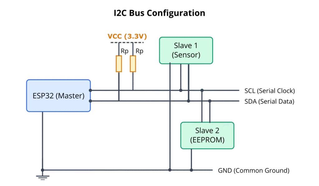
The Inter-Integrated Circuit protocol, commonly known as I2C (pronounced “eye-squared-see” or “eye-two-see”), is a widely used serial communication protocol for connecting low-speed peripheral ICs to processors and microcontrollers. It was originally developed by Philips Semiconductors (now NXP Semiconductors) in the early 1980s. I2C is popular because it uses only two bidirectional open-drain lines, Serial Data (SDA) and Serial Clock (SCL), along with a common ground, to communicate with multiple devices. This simplicity makes it ideal for short-distance, intra-board communication in embedded systems, connecting devices like sensors (temperature, humidity, accelerometers), real-time clocks (RTCs), EEPROMs, I/O expanders, and display controllers.
In this chapter, we will explore the I2C protocol in detail and learn how to utilize the ESP-IDF’s I2C driver to configure and manage I2C communication on ESP32 series microcontrollers.
Theory
I2C Basics
The I2C bus is a multi-master, multi-slave, single-ended, serial computer bus. However, in most common applications, there is a single master (like our ESP32) controlling one or more slave devices.
- SDA (Serial Data Line): Used for transmitting and receiving data between the master and slave.
- SCL (Serial Clock Line): Carries the clock signal, generated by the master, which synchronizes data transfer.
Both SDA and SCL lines are open-drain (or open-collector). This means that devices on the bus can only pull the line LOW. To make the line go HIGH, external pull-up resistors are required, connecting each line to the positive supply voltage (VCC). The value of these resistors typically ranges from 1 kΩ to 10 kΩ, depending on the bus capacitance and speed.
I2C Protocol
Communication on the I2C bus follows a defined protocol:

- START Condition (S): The master initiates communication by generating a START condition. This occurs when SDA goes from HIGH to LOW while SCL is HIGH.
- Slave Address: After the START condition, the master sends a 7-bit slave address of the device it wants to communicate with. Some devices use 10-bit addressing, but 7-bit is more common.
- Read/Write Bit (R/W): The 8th bit following the address indicates the direction of data transfer:
0: Master will write data to the slave (WRITE operation).1: Master will read data from the slave (READ operation).
- Acknowledge (ACK) / Not Acknowledge (NACK): After each byte of data is transmitted (address or data), the receiving device (either slave or master, depending on the operation) must generate an Acknowledge (ACK) bit. It does this by pulling the SDA line LOW during the 9th clock pulse. If the SDA line remains HIGH, it’s a Not Acknowledge (NACK), which can indicate an error, that the slave is busy, or that the master has finished reading data.
- Data Transfer: Data is transferred in 8-bit bytes, Most Significant Bit (MSB) first. The master generates clock pulses on SCL; data on SDA must be stable during the HIGH period of SCL. Data can only change when SCL is LOW.
- STOP Condition (P): The master terminates communication by generating a STOP condition. This occurs when SDA goes from LOW to HIGH while SCL is HIGH.
graph TD
    subgraph "I2C Write Transaction"
    direction LR
    A[START Condition] --> B{"Slave Address + Write (0)"};
    B -- ACK from Slave --> C[Data Byte 1 from Master];
    C -- ACK from Slave --> D[...];
    D -- ACK from Slave --> E[Data Byte N from Master];
    E -- ACK from Slave --> F[STOP Condition];

    classDef default fill:#f9f9f9,stroke:#333,stroke-width:1px,color:#333,font-family:'Open Sans';
    classDef primary fill:#EDE9FE,stroke:#5B21B6,stroke-width:2px,color:#5B21B6;
    classDef process fill:#DBEAFE,stroke:#2563EB,stroke-width:1px,color:#1E40AF;
    classDef success fill:#D1FAE5,stroke:#059669,stroke-width:2px,color:#065F46;
    classDef decision fill:#FEF3C7,stroke:#D97706,stroke-width:1px,color:#92400E;

    class A,F primary;
    class B decision;
    class C,D,E process;
    end
graph TD
    subgraph "I2C Read Transaction"
    direction LR
    A[START Condition] --> B{"Slave Address + Read (1)"};
    B -- ACK from Slave --> C[Data Byte 1 from Slave];
    C -- ACK from Master --> D[...];
    D -- ACK from Master --> E[Data Byte N from Slave];
    E -- NACK from Master --> F[STOP Condition];

    classDef default fill:#f9f9f9,stroke:#333,stroke-width:1px,color:#333,font-family:'Open Sans';
    classDef primary fill:#EDE9FE,stroke:#5B21B6,stroke-width:2px,color:#5B21B6;
    classDef process fill:#DBEAFE,stroke:#2563EB,stroke-width:1px,color:#1E40AF;
    classDef success fill:#D1FAE5,stroke:#059669,stroke-width:2px,color:#065F46;
    classDef decision fill:#FEF3C7,stroke:#D97706,stroke-width:1px,color:#92400E;
    classDef check fill:#FEE2E2,stroke:#DC2626,stroke-width:1px,color:#991B1B;


    class A,F primary;
    class B decision;
    class C,D,E process;
    end
Repeated START Condition (Sr)
Instead of issuing a STOP condition to end a transaction and then a START for a new one (e.g., when writing a register address and then reading its content), a master can issue a Repeated START condition. This is functionally similar to a START condition but can occur without a preceding STOP. It’s useful for atomic operations, ensuring the bus isn’t released to another master (in multi-master systems) between related transactions.
I2C Speed Modes
I2C supports several speed modes:
| Mode | Maximum Speed | Typical ESP32 Support | Notes |
|---|---|---|---|
| Standard Mode (Sm) | 100 kbit/s | Yes | Base mode, widely supported. |
| Fast Mode (Fm) | 400 kbit/s | Yes | Common for many modern sensors and peripherals. |
| Fast Mode Plus (Fm+) | 1 Mbit/s | Varies / Possible | Requires careful PCB design, appropriate pull-ups. ESP-IDF can be configured for this, but hardware limitations apply. |
| High-Speed Mode (Hs-mode) | 3.4 Mbit/s | Limited / Unlikely | Requires special master coding (active pull-up on SCL during Hs-mode) and slave support. Not typically a standard feature of ESP32 I2C peripheral. |
| Ultra Fast-mode (UFm) | 5 Mbit/s | No | Unidirectional, push-pull. Not compatible with standard I2C open-drain bus configuration. |
The ESP32’s I2C controllers typically support Standard Mode and Fast Mode well. Support for higher speeds might vary and depends on GPIO characteristics and external pull-up resistor values.
Clock Stretching
Sometimes, a slave device may not be ready to send or receive the next bit of data. In such cases, the slave can hold the SCL line LOW after the master releases it. This is called “clock stretching.” The master must wait until the slave releases SCL (allowing it to go HIGH) before proceeding with the next clock pulse. This mechanism allows slower slave devices to cope with faster masters.
ESP-IDF I2C Driver
The ESP-IDF provides a comprehensive I2C driver (driver/i2c.h) that allows configuring and operating the ESP32’s I2C controllers as masters or slaves. In this chapter, we will focus on master mode operations.
Key steps for I2C master communication using ESP-IDF:
- Configure I2C parameters: Define GPIO pins for SDA and SCL, clock speed, and mode (master).
- Install I2C driver: Initialize the I2C peripheral driver for a specific I2C port.
- Perform transactions: Create a command link, add I2C operations (START, write, read, STOP) to it, and then execute the command link. Alternatively, use simplified helper functions for basic read/write operations.
- Uninstall I2C driver: When I2C communication is no longer needed, uninstall the driver to free resources.
graph TD
    subgraph "ESP-IDF I2C Master Workflow"
    A["1- Configure I2C Parameters<br>(i2c_config_t: pins, speed, mode)"] --> B["2- Install I2C Driver<br>(i2c_param_config, i2c_driver_install)"];
    B --> C{Perform Transactions?};
    C -- Yes --> D["3- Create Command Link / Use Helper Functions<br>(e.g., i2c_cmd_link_create, i2c_master_transmit)"];
    D --> E["4- Execute Transaction<br>(i2c_master_cmd_begin / Helper function call)"];
    E --> F{More Transactions?};
    F -- Yes --> D;
    F -- No --> G["5- Uninstall I2C Driver (Optional)<br>(i2c_driver_delete)"];
    C -- No --> G;
    G --> H[End];

    classDef default fill:#f9f9f9,stroke:#333,stroke-width:1px,color:#333,font-family:'Open Sans';
    classDef primary fill:#EDE9FE,stroke:#5B21B6,stroke-width:2px,color:#5B21B6;
    classDef process fill:#DBEAFE,stroke:#2563EB,stroke-width:1px,color:#1E40AF;
    classDef success fill:#D1FAE5,stroke:#059669,stroke-width:2px,color:#065F46;
    classDef decision fill:#FEF3C7,stroke:#D97706,stroke-width:1px,color:#92400E;
    classDef check fill:#FEE2E2,stroke:#DC2626,stroke-width:1px,color:#991B1B;

    class A,B,D,E,G process;
    class C,F decision;
    class H primary;
    end
What is an I2C Command Link?
In ESP-IDF, an I2C command link is a sequence of I2C operations (like START, write byte, read byte, STOP) that are queued up and then executed by the I2C controller as a single, atomic transaction. This is particularly useful for complex interactions where multiple steps must occur without interruption (e.g., writing a register address to a sensor, then performing a repeated start, then reading data from that register).
The typical workflow for using command links is:
i2c_cmd_link_create(): Create an empty command link.i2c_master_start(): Add a START condition to the link.i2c_master_write_byte()ori2c_master_write(): Add write operations to the link. This includes sending the slave address with the R/W bit.i2c_master_read_byte()ori2c_master_read(): Add read operations to the link.i2c_master_stop(): Add a STOP condition to the link.i2c_master_cmd_begin(): Execute all queued commands in the link. This function blocks until the transaction is complete or times out.i2c_cmd_link_delete(): Free the resources used by the command link.
graph TD
    subgraph "I2C Command Link Workflow"
    A["i2c_cmd_link_create()"] --> B["Queue START<br>(i2c_master_start)"];
    B --> C["Queue Slave Address + R/W<br>(i2c_master_write_byte)"];
    C --> D["Queue Write Operations (if any)<br>(i2c_master_write_byte / i2c_master_write)"];
    D --> E["Queue Read Operations (if any)<br>(i2c_master_read_byte / i2c_master_read)"];
    E --> F["Queue STOP<br>(i2c_master_stop)"];
    F --> G{Execute Commands};
    G -- Yes --> H["i2c_master_cmd_begin()<br>Blocks until done or timeout"];
    H --> I{Transaction Successful?};
    I -- Yes --> J[Process Data / Confirm Success];
    I -- No --> K["Handle Error (Timeout, NACK, etc.)"];
    J --> L["i2c_cmd_link_delete()"];
    K --> L;
    L --> M[End of Transaction];

    classDef default fill:#f9f9f9,stroke:#333,stroke-width:1px,color:#333,font-family:'Open Sans';
    classDef primary fill:#EDE9FE,stroke:#5B21B6,stroke-width:2px,color:#5B21B6;
    classDef process fill:#DBEAFE,stroke:#2563EB,stroke-width:1px,color:#1E40AF;
    classDef success fill:#D1FAE5,stroke:#059669,stroke-width:2px,color:#065F46;
    classDef decision fill:#FEF3C7,stroke:#D97706,stroke-width:1px,color:#92400E;
    classDef check fill:#FEE2E2,stroke:#DC2626,stroke-width:1px,color:#991B1B;

    class A,B,C,D,E,F,H,L process;
    class G,I decision;
    class J success;
    class K check;
    class M primary;
    end
Practical Examples
The following examples demonstrate how to configure the ESP32 as an I2C master and communicate with a slave device.
Prerequisites:
- ESP-IDF v5.x installed and configured with VS Code.
- An ESP32 development board.
- For actual data transfer, an I2C slave device (e.g., sensor, EEPROM) connected to the ESP32. If you don’t have one, you can still study the code structure and API usage. The examples will assume a hypothetical slave device.
- Appropriate pull-up resistors (e.g., 4.7 kΩ) on SDA and SCL lines, connected to 3.3V.
Pin Assignments:
You can use any suitable GPIO pins for I2C, but ensure they are not used for other critical functions like JTAG or strapping. Common choices are GPIO21 (SDA) and GPIO22 (SCL) on many ESP32 modules, but always check your board’s schematic.
Example 1: I2C Master Initialization and Writing Data
This example shows how to initialize an I2C port as a master and write a few bytes to a slave device.
#include <stdio.h>
#include "freertos/FreeRTOS.h"
#include "freertos/task.h"
#include "driver/i2c.h"
#include "esp_log.h"

static const char *TAG = "i2c_master_example";

#define I2C_MASTER_SCL_IO           22      /*!< GPIO number used for I2C master clock */
#define I2C_MASTER_SDA_IO           21      /*!< GPIO number used for I2C master data  */
#define I2C_MASTER_NUM              I2C_NUM_0 /*!< I2C port number for master dev */
#define I2C_MASTER_FREQ_HZ          100000  /*!< I2C master clock frequency */
#define I2C_MASTER_TX_BUF_DISABLE   0       /*!< I2C master doesn't need buffer */
#define I2C_MASTER_RX_BUF_DISABLE   0       /*!< I2C master doesn't need buffer */

#define EXAMPLE_SLAVE_ADDR          0x58    /*!< Slave address of the I2C device */
#define WRITE_BIT                   I2C_MASTER_WRITE /*!< I2C master write */
#define READ_BIT                    I2C_MASTER_READ  /*!< I2C master read */
#define ACK_CHECK_EN                0x1     /*!< I2C master will check ack from slave*/
#define ACK_CHECK_DIS               0x0     /*!< I2C master will not check ack from slave */
#define ACK_VAL                     0x0     /*!< I2C ack value */
#define NACK_VAL                    0x1     /*!< I2C nack value */

/**
 * @brief Initialize I2C master
 */
static esp_err_t i2c_master_init(void)
{
    int i2c_master_port = I2C_MASTER_NUM;
    i2c_config_t conf = {
        .mode = I2C_MODE_MASTER,
        .sda_io_num = I2C_MASTER_SDA_IO,
        .scl_io_num = I2C_MASTER_SCL_IO,
        .sda_pullup_en = GPIO_PULLUP_ENABLE, // Important: Enable internal pull-ups
        .scl_pullup_en = GPIO_PULLUP_ENABLE, // Important: Enable internal pull-ups
        .master.clk_speed = I2C_MASTER_FREQ_HZ,
        // .clk_flags = 0,          /*!< Optional, you can use I2C_SCLK_SRC_FLAG_* flags to choose i2c source clock here */
    };
    esp_err_t err = i2c_param_config(i2c_master_port, &conf);
    if (err != ESP_OK) {
        ESP_LOGE(TAG, "I2C param config failed: %s", esp_err_to_name(err));
        return err;
    }
    err = i2c_driver_install(i2c_master_port, conf.mode, I2C_MASTER_RX_BUF_DISABLE, I2C_MASTER_TX_BUF_DISABLE, 0);
    if (err != ESP_OK) {
        ESP_LOGE(TAG, "I2C driver install failed: %s", esp_err_to_name(err));
        return err;
    }
    ESP_LOGI(TAG, "I2C master initialized successfully");
    return ESP_OK;
}

/**
 * @brief Test code to write data to an I2C slave
 *
 * 1. Send start condition
 * 2. Send slave address + W bit
 * 3. Send data
 * 4. Send stop condition
 */
static esp_err_t i2c_master_write_slave_example(uint8_t slave_addr, uint8_t *data_wr, size_t size)
{
    i2c_cmd_handle_t cmd = i2c_cmd_link_create();
    i2c_master_start(cmd);
    i2c_master_write_byte(cmd, (slave_addr << 1) | WRITE_BIT, ACK_CHECK_EN);
    i2c_master_write(cmd, data_wr, size, ACK_CHECK_EN);
    i2c_master_stop(cmd);
    esp_err_t ret = i2c_master_cmd_begin(I2C_MASTER_NUM, cmd, pdMS_TO_TICKS(1000)); // 1000ms timeout
    i2c_cmd_link_delete(cmd);

    if (ret == ESP_OK) {
        ESP_LOGI(TAG, "Write to slave 0x%02X successful", slave_addr);
    } else if (ret == ESP_ERR_TIMEOUT) {
        ESP_LOGW(TAG, "I2C Timeout during write to slave 0x%02X", slave_addr);
    } else {
        ESP_LOGE(TAG, "I2C Write to slave 0x%02X failed: %s", slave_addr, esp_err_to_name(ret));
    }
    return ret;
}

void app_main(void)
{
    ESP_ERROR_CHECK(i2c_master_init());
    ESP_LOGI(TAG, "I2C initialized successfully");

    uint8_t data_to_send[] = {0xAB, 0xCD, 0xEF};
    // This will attempt to write to a device with address EXAMPLE_SLAVE_ADDR
    // Ensure a device is connected or this will likely result in an error (NACK or timeout)
    esp_err_t write_status = i2c_master_write_slave_example(EXAMPLE_SLAVE_ADDR, data_to_send, sizeof(data_to_send));

    if (write_status == ESP_OK) {
        ESP_LOGI(TAG, "Data written successfully!");
    } else {
        ESP_LOGE(TAG, "Failed to write data.");
    }

    // Example of using the simpler i2c_master_transmit function (ESP-IDF v5.1+)
    // This is often more convenient for simple write operations.
    // Note: For ESP-IDF versions prior to v5.1, you might use i2c_master_write_to_device()
    // which has a slightly different signature.

    #if ESP_IDF_VERSION >= ESP_IDF_VERSION_VAL(5, 1, 0)
    ESP_LOGI(TAG, "Attempting write using i2c_master_transmit (ESP-IDF v5.1+)");
    uint8_t data_to_send_simple[] = {0x12, 0x34};
    esp_err_t ret_simple_tx = i2c_master_transmit(I2C_MASTER_NUM,
                                                  EXAMPLE_SLAVE_ADDR,
                                                  data_to_send_simple,
                                                  sizeof(data_to_send_simple),
                                                  pdMS_TO_TICKS(1000));
    if (ret_simple_tx == ESP_OK) {
        ESP_LOGI(TAG, "i2c_master_transmit successful");
    } else {
        ESP_LOGE(TAG, "i2c_master_transmit failed: %s", esp_err_to_name(ret_simple_tx));
    }
    #else
    ESP_LOGI(TAG, "i2c_master_transmit example skipped (requires ESP-IDF v5.1+)");
    #endif


    // Optional: Clean up
    // ESP_ERROR_CHECK(i2c_driver_delete(I2C_MASTER_NUM));
    // ESP_LOGI(TAG, "I2C driver deleted");
}
Code Explanation:
- Includes: Standard headers for FreeRTOS, I2C driver, and logging.
- Defines:
I2C_MASTER_SCL_IO,I2C_MASTER_SDA_IO: GPIO pins for SCL and SDA. Adjust these to your board’s connections.I2C_MASTER_NUM: The I2C controller port to use (e.g.,I2C_NUM_0orI2C_NUM_1).I2C_MASTER_FREQ_HZ: Desired I2C clock frequency (100kHz for Standard Mode).EXAMPLE_SLAVE_ADDR: The 7-bit address of the target slave device. This must match your actual device.WRITE_BIT,READ_BIT,ACK_CHECK_EN, etc.: Constants for I2C operations.
i2c_master_init()function:- Creates an
i2c_config_tstructure.
- Creates an
| Member | Type | Description for Master Mode | Example Value |
|---|---|---|---|
| mode | i2c_mode_t | Set to I2C_MODE_MASTER to configure as I2C master. | I2C_MODE_MASTER |
| sda_io_num | int | GPIO number for the SDA (data) line. | 21, GPIO_NUM_21 |
| scl_io_num | int | GPIO number for the SCL (clock) line. | 22, GPIO_NUM_22 |
| sda_pullup_en | gpio_pullup_t | Enable internal pull-up for SDA line. GPIO_PULLUP_ENABLE or GPIO_PULLUP_DISABLE. External pull-ups are generally preferred. | GPIO_PULLUP_ENABLE |
| scl_pullup_en | gpio_pullup_t | Enable internal pull-up for SCL line. GPIO_PULLUP_ENABLE or GPIO_PULLUP_DISABLE. External pull-ups are generally preferred. | GPIO_PULLUP_ENABLE |
| master.clk_speed | uint32_t | I2C clock frequency in Hz for master mode. | 100000 (for 100kHz) |
| clk_flags | uint32_t | Optional flags for I2C clock source. Usually set to 0 for default. Can use I2C_SCLK_SRC_FLAG_*. | 0 |
i2c_master_init- Sets
modetoI2C_MODE_MASTER. - Assigns
sda_io_numandscl_io_num. - Crucially,
sda_pullup_enandscl_pullup_enare set toGPIO_PULLUP_ENABLE. While external pull-ups are strongly recommended and often necessary for reliable operation (especially at higher speeds or with longer wires), enabling internal pull-ups can sometimes work for simple setups or as a fallback. Always prefer appropriately sized external pull-up resistors. - Sets
master.clk_speed. - Calls
i2c_param_config()to apply the configuration. - Calls
i2c_driver_install()to install the driver for the specified port. RX/TX buffers are disabled for master mode as data is handled directly via command links or helper functions.
- Sets
i2c_master_write_slave_example()function:i2c_cmd_link_create(): Creates a new command link.i2c_master_start(cmd): Queues a START condition.i2c_master_write_byte(cmd, (slave_addr << 1) | WRITE_BIT, ACK_CHECK_EN): Queues the slave address. The 7-bit address is shifted left by one bit, and the LSB is set toWRITE_BIT(0).ACK_CHECK_ENenables checking for an ACK from the slave.i2c_master_write(cmd, data_wr, size, ACK_CHECK_EN): Queues the data bytes to be written.i2c_master_stop(cmd): Queues a STOP condition.i2c_master_cmd_begin(I2C_MASTER_NUM, cmd, pdMS_TO_TICKS(1000)): Executes all queued commands onI2C_MASTER_NUM. It waits for up to 1000 milliseconds for the transaction to complete.i2c_cmd_link_delete(cmd): Frees the command link.- Error handling logs the outcome.
app_main()function:- Calls
i2c_master_init(). - Defines some sample data
data_to_send. - Calls
i2c_master_write_slave_example()to send the data. - Includes an example of
i2c_master_transmit()(available in ESP-IDF v5.1+), which simplifies write operations. - Optionally,
i2c_driver_delete()can be called to uninstall the driver if I2C is no longer needed.
- Calls
Build Instructions:
- Save the code as
main.cin themaindirectory of your ESP-IDF project. - Ensure your
CMakeLists.txtin themaindirectory includesidf_component_register(SRCS "main.c" INCLUDE_DIRS "."). - Open a VS Code terminal with the ESP-IDF environment activated.
- Run
idf.py buildto compile the project.
Run/Flash/Observe Steps:
- Connect your ESP32 board to your computer.
- Connect your I2C slave device to the specified SDA, SCL pins, VCC (3.3V), and GND. Ensure pull-up resistors are in place.
- Run
idf.py -p (PORT) flash monitor(replace(PORT)with your ESP32’s serial port, e.g.,/dev/ttyUSB0orCOM3). - Observe the ESP_LOG output.
- If a slave device is connected and responds with ACKs, you should see “Write to slave … successful” and “Data written successfully!”.
- If no device is connected, or if the address is wrong, or if pull-ups are missing, you’ll likely see an error like “I2C Write to slave … failed: esp_err_t: 0x107 (ESP_ERR_TIMEOUT)” or another I2C error code related to NACK.
- A logic analyzer connected to SDA and SCL lines would be invaluable for observing the actual I2C signals.
Tip: If you don’t have an I2C slave device, you can still build and run this code. The
i2c_master_cmd_begincall will likely time out or return an error because no slave will acknowledge the address. This helps you verify the master-side setup.
Example 2: I2C Master Reading Data
This example demonstrates how to read data from an I2C slave device.
#include <stdio.h>
#include "freertos/FreeRTOS.h"
#include "freertos/task.h"
#include "driver/i2c.h"
#include "esp_log.h"
#include "esp_idf_version.h" // For ESP_IDF_VERSION

static const char *TAG = "i2c_master_read_example";

#define I2C_MASTER_SCL_IO           22      /*!< GPIO number used for I2C master clock */
#define I2C_MASTER_SDA_IO           21      /*!< GPIO number used for I2C master data  */
#define I2C_MASTER_NUM              I2C_NUM_0 /*!< I2C port number for master dev */
#define I2C_MASTER_FREQ_HZ          100000  /*!< I2C master clock frequency */
#define I2C_MASTER_TX_BUF_DISABLE   0       /*!< I2C master doesn't need buffer */
#define I2C_MASTER_RX_BUF_DISABLE   0       /*!< I2C master doesn't need buffer */

#define EXAMPLE_SLAVE_ADDR          0x58    /*!< Slave address of the I2C device */
#define WRITE_BIT                   I2C_MASTER_WRITE /*!< I2C master write */
#define READ_BIT                    I2C_MASTER_READ  /*!< I2C master read */
#define ACK_CHECK_EN                0x1     /*!< I2C master will check ack from slave*/
#define ACK_VAL                     0x0     /*!< I2C ack value */
#define NACK_VAL                    0x1     /*!< I2C nack value */

// Re-use i2c_master_init from Example 1 or define it here
static esp_err_t i2c_master_init(void)
{
    int i2c_master_port = I2C_MASTER_NUM;
    i2c_config_t conf = {
        .mode = I2C_MODE_MASTER,
        .sda_io_num = I2C_MASTER_SDA_IO,
        .scl_io_num = I2C_MASTER_SCL_IO,
        .sda_pullup_en = GPIO_PULLUP_ENABLE,
        .scl_pullup_en = GPIO_PULLUP_ENABLE,
        .master.clk_speed = I2C_MASTER_FREQ_HZ,
    };
    esp_err_t err = i2c_param_config(i2c_master_port, &conf);
    if (err != ESP_OK) {
        ESP_LOGE(TAG, "I2C param config failed: %s", esp_err_to_name(err));
        return err;
    }
    err = i2c_driver_install(i2c_master_port, conf.mode, I2C_MASTER_RX_BUF_DISABLE, I2C_MASTER_TX_BUF_DISABLE, 0);
    if (err != ESP_OK) {
        ESP_LOGE(TAG, "I2C driver install failed: %s", esp_err_to_name(err));
        return err;
    }
    ESP_LOGI(TAG, "I2C master initialized successfully for reading");
    return ESP_OK;
}


/**
 * @brief Test code to read data from an I2C slave
 *
 * 1. Send start condition
 * 2. Send slave address + R bit
 * 3. Read data from slave (master sends ACK for all but last byte)
 * 4. Master sends NACK for the last byte
 * 5. Send stop condition
 */
static esp_err_t i2c_master_read_slave_example(uint8_t slave_addr, uint8_t *data_rd, size_t size)
{
    if (size == 0) {
        return ESP_OK;
    }
    i2c_cmd_handle_t cmd = i2c_cmd_link_create();
    i2c_master_start(cmd);
    i2c_master_write_byte(cmd, (slave_addr << 1) | READ_BIT, ACK_CHECK_EN);
    if (size > 1) {
        i2c_master_read(cmd, data_rd, size - 1, ACK_VAL); // Read all but the last byte, sending ACK
    }
    i2c_master_read_byte(cmd, data_rd + size - 1, NACK_VAL); // Read the last byte, sending NACK
    i2c_master_stop(cmd);
    esp_err_t ret = i2c_master_cmd_begin(I2C_MASTER_NUM, cmd, pdMS_TO_TICKS(1000));
    i2c_cmd_link_delete(cmd);

    if (ret == ESP_OK) {
        ESP_LOGI(TAG, "Read from slave 0x%02X successful", slave_addr);
        for (int i = 0; i < size; i++) {
            ESP_LOGI(TAG, "Data byte %d: 0x%02X", i, data_rd[i]);
        }
    } else if (ret == ESP_ERR_TIMEOUT) {
        ESP_LOGW(TAG, "I2C Timeout during read from slave 0x%02X", slave_addr);
    } else {
        ESP_LOGE(TAG, "I2C Read from slave 0x%02X failed: %s", slave_addr, esp_err_to_name(ret));
    }
    return ret;
}

void app_main(void)
{
    uint8_t data_buffer[8]; // Buffer to store read data

    ESP_ERROR_CHECK(i2c_master_init());
    ESP_LOGI(TAG, "I2C initialized successfully for read example");

    // This will attempt to read from a device with address EXAMPLE_SLAVE_ADDR
    // The slave device must be prepared to send data upon receiving its address with R/W=1
    esp_err_t read_status = i2c_master_read_slave_example(EXAMPLE_SLAVE_ADDR, data_buffer, sizeof(data_buffer));

    if (read_status == ESP_OK) {
        ESP_LOGI(TAG, "Data read successfully!");
        // Process data_buffer here
    } else {
        ESP_LOGE(TAG, "Failed to read data.");
    }

    // Example of using the simpler i2c_master_receive function (ESP-IDF v5.1+)
    // This is often more convenient for simple read operations.
    // Note: For ESP-IDF versions prior to v5.1, you might use i2c_master_read_from_device()
    // which has a slightly different signature.
    #if ESP_IDF_VERSION >= ESP_IDF_VERSION_VAL(5, 1, 0)
    ESP_LOGI(TAG, "Attempting read using i2c_master_receive (ESP-IDF v5.1+)");
    uint8_t data_buffer_simple[4];
    esp_err_t ret_simple_rx = i2c_master_receive(I2C_MASTER_NUM,
                                                 EXAMPLE_SLAVE_ADDR,
                                                 data_buffer_simple,
                                                 sizeof(data_buffer_simple),
                                                 pdMS_TO_TICKS(1000));
    if (ret_simple_rx == ESP_OK) {
        ESP_LOGI(TAG, "i2c_master_receive successful. Data:");
        for (int i = 0; i < sizeof(data_buffer_simple); i++) {
            ESP_LOGI(TAG, "Byte %d: 0x%02X", i, data_buffer_simple[i]);
        }
    } else {
        ESP_LOGE(TAG, "i2c_master_receive failed: %s", esp_err_to_name(ret_simple_rx));
    }
    #else
    ESP_LOGI(TAG, "i2c_master_receive example skipped (requires ESP-IDF v5.1+)");
    #endif

    // Optional: Clean up
    // ESP_ERROR_CHECK(i2c_driver_delete(I2C_MASTER_NUM));
    // ESP_LOGI(TAG, "I2C driver deleted");
}
Code Explanation:
- The
i2c_master_init()function is the same as in the write example. i2c_master_read_slave_example()function:- Similar structure using command links.
i2c_master_write_byte(cmd, (slave_addr << 1) | READ_BIT, ACK_CHECK_EN): Queues the slave address with the LSB set toREAD_BIT(1).i2c_master_read(cmd, data_rd, size - 1, ACK_VAL): If reading multiple bytes (size > 1), this queues read operations for all but the last byte. For each of these bytes, the master sends anACK_VAL(0) to signal the slave to send another byte.i2c_master_read_byte(cmd, data_rd + size - 1, NACK_VAL): Queues a read operation for the final byte. The master sends aNACK_VAL(1) after receiving this byte to signal the slave that the read transmission is complete.- The rest of the function (start, stop, execute, delete link) is similar to the write example.
app_main()function:- Initializes I2C.
- Declares a
data_bufferto store the incoming data. - Calls
i2c_master_read_slave_example()to read data. - Includes an example of
i2c_master_receive()(available in ESP-IDF v5.1+), which simplifies read operations.
Build and Run/Flash/Observe Steps:
Follow the same build, flash, and observe steps as in Example 1.
- If a slave device is connected, configured at
EXAMPLE_SLAVE_ADDR, and sends data, you will see the “Read from slave … successful” message followed by the received data bytes. - Otherwise, expect timeout or NACK errors.
Warning: Many I2C devices (like sensors) require you to first write to a specific register address within the slave to tell it which data you want to read. This often involves a write transaction (to send the register address) followed by a repeated START and then a read transaction. The
i2c_master_write_read_device()function or a more complex command link sequence would be used for such cases. The exercise section will touch upon this.
Variant Notes
The ESP32 family offers varying numbers of I2C controllers and flexibility in pin assignments.
- ESP32:
- Two I2C controllers (
I2C_NUM_0,I2C_NUM_1). - Can be mapped to almost any GPIO pin.
- Two I2C controllers (
- ESP32-S2:
- Two I2C controllers (
I2C_NUM_0,I2C_NUM_1). - Can be mapped to almost any GPIO pin.
- Two I2C controllers (
- ESP32-S3:
- Two I2C controllers (
I2C_NUM_0,I2C_NUM_1). - Can be mapped to almost any GPIO pin.
- Two I2C controllers (
- ESP32-C3:
- One I2C controller (
I2C_NUM_0). - Can be mapped to almost any GPIO pin.
- One I2C controller (
- ESP32-C6:
- One I2C controller (
I2C_NUM_0). - Can be mapped to almost any GPIO pin. Note: Some early documentation might suggest two, but official TRM and ESP-IDF headers confirm one I2C controller for general use.
- One I2C controller (
- ESP32-H2:
- Two I2C controllers (
I2C_NUM_0,I2C_NUM_1). - Can be mapped to almost any GPIO pin.
- Two I2C controllers (
| ESP32 Variant | Number of I2C Controllers | Pin Assignment Flexibility | Typical Max Speed (Practical) |
|---|---|---|---|
| ESP32 | 2 (I2C_NUM_0, I2C_NUM_1) | High (most GPIOs) | 100kHz (Standard), 400kHz (Fast). Higher possible with care. |
| ESP32-S2 | 2 (I2C_NUM_0, I2C_NUM_1) | High (most GPIOs) | 100kHz, 400kHz. Higher possible with care. |
| ESP32-S3 | 2 (I2C_NUM_0, I2C_NUM_1) | High (most GPIOs) | 100kHz, 400kHz. Higher possible with care. |
| ESP32-C3 | 1 (I2C_NUM_0) | High (most GPIOs) | 100kHz, 400kHz. Higher possible with care. |
| ESP32-C6 | 1 (I2C_NUM_0) | High (most GPIOs) | 100kHz, 400kHz. Higher possible with care. |
| ESP32-H2 | 2 (I2C_NUM_0, I2C_NUM_1) | High (most GPIOs) | 100kHz, 400kHz. Higher possible with care. |
Key Considerations:
- Number of Controllers: If your application needs to interface with I2C devices on separate buses or requires more than one master interface, choose a variant with multiple controllers.
- Pin Multiplexing: While I2C pins are flexible, always consult your specific ESP32 module’s datasheet and your development board’s schematic to avoid conflicts with other peripherals (e.g., JTAG, SPI flash pins, strapping pins).
- Internal Pull-ups: While ESP32 GPIOs offer internal pull-ups, their strength might not be optimal for all I2C bus conditions (especially higher speeds or longer traces). External pull-up resistors (e.g., 2.2kΩ to 10kΩ, typically 4.7kΩ for 100/400kHz) are highly recommended for reliable I2C communication. Connect them from SDA to VCC and SCL to VCC.
- Maximum Frequency: The maximum achievable I2C frequency can be influenced by GPIO drive strength, bus capacitance (determined by wire length, number of devices, PCB layout), and pull-up resistor values. The ESP-IDF driver allows configuring standard (100kHz) and fast (400kHz) modes. Higher speeds might be possible but require careful design.
When porting code between variants, ensure you are using the correct I2C_NUM_x and that the chosen GPIO pins are available and suitable on the target hardware. The core I2C driver API remains consistent across these variants.
Common Mistakes & Troubleshooting Tips
| Mistake / Issue | Symptom(s) | Troubleshooting / Solution |
|---|---|---|
| Missing/Incorrect Pull-Up Resistors | No communication, SDA/SCL lines stay LOW or HIGH unexpectedly, ESP_ERR_TIMEOUT, NACKs. | Ensure external pull-up resistors (e.g., 4.7kΩ for 3.3V, 100/400kHz) are present on SDA and SCL, connected to VCC. Verify sda_pullup_en / scl_pullup_en if relying on internal (though external are preferred). |
| Incorrect Slave Address | No ACK from slave, i2c_master_cmd_begin returns error (often ESP_FAIL or ESP_ERR_TIMEOUT if no device at all). | Verify the 7-bit slave address from datasheet. If datasheet gives 8-bit (e.g., 0xA0 write, 0xA1 read), use the 7-bit form (e.g., 0x50). Use an I2C scanner to find connected devices. |
| SDA and SCL Lines Swapped | No communication, erratic behavior. Logic analyzer shows no valid I2C frames. | Carefully check wiring: Master SDA to Slave SDA, Master SCL to Slave SCL. |
| Incorrect I2C Port or GPIO Config | Driver installation fails, or no signals on expected pins. ESP_ERR_INVALID_ARG. | Verify I2C_MASTER_NUM matches the intended controller. Ensure sda_io_num and scl_io_num are correct and not used by other peripherals (JTAG, strapping pins). |
| Timing Issues / Clock Speed Too High | Intermittent errors, NACKs, corrupted data, especially with longer wires or multiple devices. | Start with I2C_MASTER_FREQ_HZ = 100000. Ensure slave supports the speed. Check pull-up values; stronger pull-ups (e.g., 2.2kΩ) might be needed for higher speeds/capacitance. |
| Driver Not Initialized | Crashes or errors when calling I2C functions (ESP_ERR_INVALID_STATE). | Ensure i2c_param_config() and i2c_driver_install() are called and succeed before I2C operations. Check their return codes. |
| ACK/NACK Mismanagement | Master expects ACK but gets NACK (or vice-versa), leading to transaction failure. Data reads might stop prematurely or read garbage. | Check return of i2c_master_cmd_begin(). For reads, master ACKs bytes until the last one, then NACKs. For writes, slave ACKs address and data. Use logic analyzer to verify. |
| Power Issues | Device not responding, unstable operation. | Ensure slave device is properly powered (correct voltage, sufficient current). Check common ground connection. |
| Bus Contention / Stuck Lines | SDA or SCL line stuck LOW or HIGH. No communication possible. | Check if any device is holding the line. Power cycle devices. Ensure no short circuits. In rare cases, a slave might need a reset. Clock stretching by slave should not be indefinite. |
| Timeout Too Short | ESP_ERR_TIMEOUT from i2c_master_cmd_begin() even if slave is slow but responsive. | Increase ticks_to_wait in i2c_master_cmd_begin(), especially if slave device is known to be slow or performs clock stretching. |
Debugging Tip: A logic analyzer is an invaluable tool for debugging I2C communication. It allows you to see the actual signals on the SDA and SCL lines, decode the protocol, and identify issues like missing ACKs, incorrect addresses, or timing problems.
Exercises
- Modify Write Example for Register Access:Many I2C devices require writing to a specific register address before writing or reading data. Modify Example 1 (i2c_master_write_slave_example) to first write a 1-byte “register address” and then write 2 bytes of “data” to that register in a single I2C transaction (using one START and one STOP).Hint: You’ll add another i2c_master_write() or i2c_master_write_byte() for the register address before writing the actual data bytes.
- Implement write-then-read for a Sensor Register:Combine write and read operations for a common sensor scenario: write a register address to a slave, then perform a repeated START, then read data from that register. Create a function esp_err_t i2c_master_write_then_read_slave(uint8_t slave_addr, uint8_t* reg_addr_data, size_t reg_addr_size, uint8_t* read_data, size_t read_size).Hint: Use i2c_master_start(), i2c_master_write_byte() (for slave addr + W), i2c_master_write() (for reg_addr_data), then i2c_master_start() again (repeated start), i2c_master_write_byte() (for slave addr + R), then i2c_master_read(), and finally i2c_master_stop().Alternatively, investigate the i2c_master_transmit_receive() function (ESP-IDF v5.1+) or i2c_master_write_read_device() (older versions) for a simpler way to achieve this.
- I2C Bus Scanner:Write a function void i2c_scan_bus(i2c_port_t i2c_num) that attempts to communicate with all possible 7-bit I2C addresses (from 0x01 to 0x7F). For each address, try to send just the address and check for an ACK. If an ACK is received, print the address of the found device. This is useful for discovering connected I2C devices.Hint: Loop through addresses. For each, create a command link with START, i2c_master_write_byte(cmd, (addr << 1) | WRITE_BIT, ACK_CHECK_EN), STOP. If i2c_master_cmd_begin() returns ESP_OK, a device responded.
- Interface with a Real I2C Sensor (Conceptual):If you have a common I2C sensor like a BMP180 (pressure/temperature), MPU6050 (accelerometer/gyroscope), or AHT20 (temperature/humidity):
- Find its datasheet and I2C address.
- Identify the registers for reading sensor data (e.g., temperature).
- Use the
write-then-readpattern from Exercise 2 (or the simplified helper functions) to read data from the sensor. - Parse the received bytes according to the sensor’s datasheet to get meaningful values.
- (This is a more involved task, focus on the I2C communication part first).
- Error Handling and Retry Logic:Modify one of the previous examples to include basic retry logic. If i2c_master_cmd_begin() fails (e.g., due to a timeout or NACK), wait for a short period (e.g., 100ms) and retry the I2C transaction a few times before giving up. Log each attempt and the final status.
Summary
- I2C is a two-wire (SDA, SCL) serial protocol for communication between a master and multiple slave devices.
- Open-drain lines require external pull-up resistors for proper operation.
- Communication involves START, slave address (7-bit or 10-bit) + R/W bit, ACK/NACK, data bytes, and STOP conditions.
- ESP-IDF provides a comprehensive I2C driver for master and slave modes.
- Master operations involve configuring the I2C port, installing the driver, and using command links (
i2c_cmd_link_create, etc.) or helper functions (i2c_master_transmit,i2c_master_receive) to execute transactions. - Proper GPIO pin selection, slave addressing, and pull-up resistor usage are critical for reliable I2C communication.
- Different ESP32 variants offer one or two I2C controllers, but the API usage is consistent.
- A logic analyzer is highly beneficial for troubleshooting I2C issues.
Further Reading
- ESP-IDF I2C Driver Documentation:
- ESP-IDF I2C API Reference (Replace
esp32with your target chip, e.g.,esp32s3,esp32c3, if needed, though the general API is similar).
- ESP-IDF I2C API Reference (Replace
- I2C Protocol Specification:
- NXP (formerly Philips) I2C Bus Specification (UM10204): A search for “UM10204 I2C-bus specification” will find the official document.
- Application Notes and Tutorials:
- SparkFun: I2C Tutorial
- Adafruit: I2C Addresses
- TI: Understanding the I2C Bus
