
Chapter 192: HART Protocol Communication
Chapter Objectives
By the end of this chapter, you will be able to:
- Understand the fundamentals of the HART (Highway Addressable Remote Transducer) protocol.
- Describe the hybrid (analog + digital) communication mechanism of HART.
- Explain the roles of HART Masters and Slaves, and the different communication modes (point-to-point, multidrop).
- Recognize the structure of HART messages and the Bell 202 FSK modulation technique.
- Understand how an ESP32 can interface with a HART network using an external HART modem IC.
- Configure UART on the ESP32 to communicate with a HART modem IC.
- Outline the process of sending HART commands and receiving responses.
- Identify common issues and troubleshooting strategies for basic HART communication setups.
- Appreciate the differences when implementing HART solutions across various ESP32 variants.
Introduction
In the realm of industrial process automation, reliable and robust communication with field instruments (sensors and actuators) is paramount. For decades, the 4-20mA analog current loop has been the backbone for transmitting process variables. However, as instrumentation became “smarter,” the need arose to extract more than just a single analog value. This led to the development of the HART (Highway Addressable Remote Transducer) protocol.
HART is a globally recognized open standard that superimposes digital communication signals on top of the standard 4-20mA analog signal. This hybrid approach allows legacy systems to continue using the analog value while enabling access to a wealth of additional information from the device, such as device status, diagnostics, multiple process variables, and configuration parameters.
While an ESP32 cannot directly generate or interpret the HART FSK (Frequency Shift Keying) signals on a 4-20mA loop, it can serve as an intelligent host controller for a dedicated HART modem IC. This chapter will explore the HART protocol’s theory and demonstrate how an ESP32, using ESP-IDF, can be programmed to interact with HART-enabled devices through such a modem, paving the way for applications like custom HART gateways, data loggers, and diagnostic tools.
Theory
What is HART?
HART, standing for Highway Addressable Remote Transducer Protocol, is a bi-directional communication protocol predominantly used in process industries. It allows digital information to be superimposed on the conventional 4-20mA analog signal loop without interfering with the analog signal itself. This means a host system can receive the primary process variable as a 4-20mA signal while simultaneously communicating digitally with the field device for additional data or configuration.
Key Characteristics:
- Hybrid Communication: Combines analog (4-20mA) and digital communication.
- Master-Slave Protocol: A master (e.g., control system, handheld communicator, or ESP32 with modem) initiates communication, and slave devices (field instruments) respond.
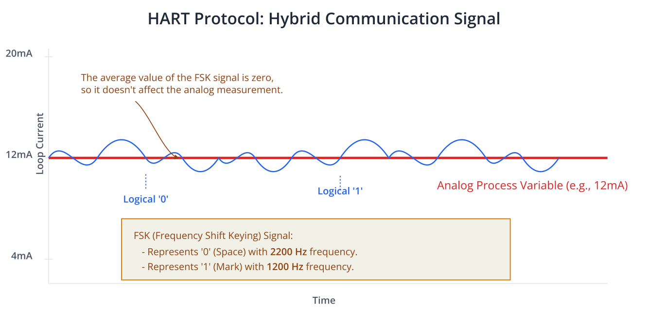
- FSK Modulation: Uses Bell 202 standard Frequency Shift Keying to encode digital signals.
- A frequency of 1200 Hz represents a logical ‘1’ (mark).
- A frequency of 2200 Hz represents a logical ‘0’ (space).
- These FSK signals have an average value of zero, so they do not affect the 4-20mA analog signal.
- Open Standard: Managed by the FieldComm Group, ensuring interoperability.
- Widely Adopted: A vast installed base of HART-enabled devices exists globally.
HART System Components
A basic HART system involves:
- HART Master:
- Initiates communication requests (commands) to slave devices.
- Can be a Distributed Control System (DCS), Programmable Logic Controller (PLC), a PC with a HART modem, a handheld HART communicator, or an ESP32 system equipped with a HART modem.
- There can be primary and secondary masters.
- HART Slave Device:
- A field instrument like a transmitter (pressure, temperature, flow, level), valve positioner, or actuator.
- Responds to commands from a master.
- Provides the 4-20mA analog signal representing its primary measured variable (in point-to-point mode).
- HART Modem:
- A crucial component that modulates digital data from a microcontroller (like ESP32) into the HART FSK signal to be sent over the 4-20mA loop.
- Demodulates incoming FSK signals from the loop back into digital data for the microcontroller.
- The ESP32 communicates with the modem, typically via UART or SPI.
- Power Supply and Loop Resistor:
- A DC power supply (typically 24V) powers the 4-20mA loop.
- A loop resistor (typically 250 Ohms) is required to convert the current signal into a voltage that can be read by an analog input channel or across which the FSK signal is developed.
- Wiring:
- Standard instrumentation twisted-pair wiring.
HART Communication Modes
HART supports two main communication modes:
- Point-to-Point Mode:
- This is the most common mode.A single HART master communicates with a single HART slave device over a 4-20mA loop.The 4-20mA analog signal represents the primary process variable (e.g., temperature, pressure).Digital communication is used to transmit additional variables, diagnostic data, and configuration parameters.The slave device address is typically 0 in this mode.
graph TD
    subgraph Control Room
        Master[<b>HART Master</b><br>e.g., ESP32 with Modem, PLC]
    end

    subgraph Field
        Slave(<b>HART Slave Device</b><br>e.g., Pressure Transmitter)
    end

    Master -- "4-20mA Analog Signal<br>+<br>Digital FSK Data" --> Slave

    classDef default fill:#DBEAFE,stroke:#2563EB,stroke-width:1px,color:#1E40AF
    classDef startNode fill:#EDE9FE,stroke:#5B21B6,stroke-width:2px,color:#5B21B6
    classDef endNode fill:#D1FAE5,stroke:#059669,stroke-width:2px,color:#065F46

    class Master startNode
    class Slave endNode
- Multidrop Mode (Bus Mode):
- A single HART master communicates with multiple (up to 15 or 63, depending on HART revision and addressing) slave devices connected in parallel on the same pair of wires.In this mode, the analog current signal of each device is fixed at 4mA (to power the device). The current loop cannot be used to transmit the primary process variable as an analog signal.All process variables and other data are transmitted digitally.Each slave device must have a unique polling address (1-15 or 1-63).This mode is less common but useful for daisy-chaining multiple devices where only digital data is needed.
graph TD
    subgraph Control Room
        Master[<b>HART Master</b><br>e.g., ESP32 with Modem, PC]
    end

    subgraph "Field Bus (Single Wire Pair)"
        Slave1(Slave #1<br>Address: 1)
        Slave2(Slave #2<br>Address: 2)
        Slave3(Slave #3<br>Address: 3)
        SlaveN(Slave #n<br>Address: n)
    end

    Master -- "<b>Digital FSK Data Only</b><br>(Analog signal fixed at 4mA)" --> Slave1
    Master --> Slave2
    Master --> Slave3
    Master --> SlaveN

    linkStyle 0,1,2,3 stroke-width:2px,stroke:#6D28D9

    classDef default fill:#DBEAFE,stroke:#2563EB,stroke-width:1px,color:#1E40AF
    classDef startNode fill:#EDE9FE,stroke:#5B21B6,stroke-width:2px,color:#5B21B6
    classDef endNode fill:#D1FAE5,stroke:#059669,stroke-width:2px,color:#065F46

    class Master startNode
    class Slave1,Slave2,Slave3,SlaveN endNode
HART Protocol Layers
HART communication can be understood using a simplified OSI model:
- Physical Layer (L1):
- Defines the transmission medium (4-20mA current loop).
- Specifies the Bell 202 FSK modulation technique (1200 Hz for ‘1’, 2200 Hz for ‘0’).
- Data rate is 1200 bits per second.
- Ensures the digital signal does not interfere with the analog signal.
- Data Link Layer (L2):
- Manages reliable data transfer between master and slave.Defines the HART message frame format.Handles device addressing and media access control (master initiates).Includes error checking (checksum).
- Preamble: A sequence of 5 to 20
0xFFbytes to synchronize the receiver.Start Delimiter (STX): A unique byte indicating the start of the message frame.- Master to Slave:
0x02(long address),0x06(short address)Slave to Master:0x06(no error),0x86(communication error in slave),0x16(busy)
- Short Address (Polling Address): 1 byte (0-15 or 0-63). Master includes its address (typically 0 or 1) and slave’s polling address.Long Address (Unique Identifier): 5 bytes. Manufacturer ID (2 bytes), Device Type (1 byte), Device ID (2 bytes). Used for Command 0.
- In slave responses, the first 1 or 2 bytes are Status Bytes indicating command execution status.The rest is the actual data payload.
- Master to Slave:
- Application Layer (L7):
- Defines the HART command set.
- Provides a standardized way for devices to interpret and respond to commands.
- HART Commands:
- Universal Commands: Implemented by all HART devices (e.g., Command 0: Read Unique Identifier, Command 1: Read Primary Variable, Command 2: Read Loop Current and Percent of Range, Command 3: Read Dynamic Variables and Loop Current).
- Common Practice Commands: Provide functions common to many, but not all, field devices (e.g., configuration, calibration).
- Device-Specific Commands: Allow manufacturers to implement unique features for their devices. These are documented in the device’s manual and IODD/DD file.
- Device Description (DD) / Device Description Language (DDL):
- A formal language used to describe the parameters and capabilities of a HART device.
- DD files allow host applications (like configuration tools or asset management systems) to communicate with any HART device without needing custom drivers for each one. The host interprets the DD to understand the device’s menu structure, data types, and methods.
| Field | Size (Bytes) | Description |
|---|---|---|
| Preamble | 5 – 20 | A sequence of 0xFF bytes used by the receiver to synchronize with the FSK signal. Required for master-to-slave messages. |
| Start Delimiter (STX) | 1 | A unique byte that marks the beginning of the frame and indicates message type (master/slave, address format). E.g., 0x02 for master request with long address. |
| Address | 1 or 5 | Specifies the destination device. Can be a 1-byte short polling address (0-63) or a 5-byte unique identifier (long address). |
| Command | 1 | The command code indicating the action to be performed (e.g., 0x00 to read unique ID, 0x01 to read primary variable). |
| Byte Count | 1 | Indicates the number of bytes in the following Data + Status fields. |
| Data / Status | 0 – 255 | Payload of the message. In slave responses, the first 1 or 2 bytes are status codes indicating command success or failure. The rest is the requested data. |
| Checksum (LRC) | 1 | Longitudinal Redundancy Check. An XOR of all bytes from the Start Delimiter to the end of the Data field, used for error detection. |
HART Modem ICs
The ESP32, being a digital microcontroller, cannot directly produce or decode the FSK signals required for HART communication on a 4-20mA loop. It needs an external HART Modem IC.
These ICs typically provide:
- FSK modulation and demodulation capabilities (Bell 202).
- Interface circuitry to connect to the 4-20mA loop.
- A digital interface (commonly UART, sometimes SPI) for the host microcontroller (ESP32).
- Filtering to separate the FSK signal from the analog loop current.
Examples of HART Modem ICs (availability may vary, always check for current parts):
- A5191HRT (ON Semiconductor)
- DS8500 (Maxim Integrated – older part)
- Various modules incorporating modem ICs.
The ESP32 sends digital data (representing a HART frame) to the modem via UART. The modem then converts this into FSK signals and transmits it on the loop. Conversely, when FSK signals are received from the loop, the modem demodulates them into digital data and sends it to the ESP32.
Practical Examples
This section provides conceptual examples of how an ESP32 can interface with a HART modem IC using UART to send commands and receive responses. The actual implementation details for constructing and parsing HART frames, and controlling the modem, can be complex and depend heavily on the specific modem IC used.
Assumptions:
- You have an ESP32 development board.
- You have a HART modem IC (e.g., on an evaluation board or custom PCB).
- The HART modem IC interfaces with the ESP32 via UART.
- You have a HART-compatible slave device for testing, or a HART simulator.
- A proper 4-20mA loop is set up with power supply and loop resistor.
Hardware Setup
- ESP32 to HART Modem IC:
- Connect ESP32 UART TX to Modem UART RX.
- Connect ESP32 UART RX to Modem UART TX.
- Connect GND.
- The modem may require other control signals (e.g., RTS/CTS for flow control, reset, carrier detect). Consult the modem’s datasheet.
- HART Modem IC to 4-20mA Loop:
- Connect the modem’s analog interface pins to the 4-20mA current loop according to its datasheet. This usually involves connecting in series with the loop or across the loop resistor.
- HART Slave Device:
- Connect the HART slave device into the 4-20mA loop.
Software Setup
- Create a new ESP-IDF Project:
idf.py create-project hart_master_example cd hart_master_example - Configure Project: Use
idf.py menuconfigif necessary (e.g., for UART pin changes).
Code Snippet 1: UART Configuration for HART Modem
This initializes UART communication between the ESP32 and the HART modem IC. The baud rate for this interface is typically 1200 bps, as the HART protocol itself operates at this speed, and many modems expect the digital side to match. However, some modems might support higher UART speeds to the host controller. Always check your modem’s datasheet.
#include <stdio.h>
#include <string.h>
#include "freertos/FreeRTOS.h"
#include "freertos/task.h"
#include "driver/uart.h"
#include "driver/gpio.h"
#include "esp_log.h"

static const char *TAG = "HART_MASTER";

// UART Configuration for communication with HART Modem IC
#define MODEM_UART_NUM            UART_NUM_2 // Example: Using UART2
#define MODEM_UART_TXD_PIN        (GPIO_NUM_17)
#define MODEM_UART_RXD_PIN        (GPIO_NUM_16)
#define MODEM_UART_RTS_PIN        (UART_PIN_NO_CHANGE) // Or a GPIO if modem uses RTS
#define MODEM_UART_CTS_PIN        (UART_PIN_NO_CHANGE) // Or a GPIO if modem uses CTS

// HART standard baud rate is 1200 bps. Some modems might allow higher speeds
// for the DTE (ESP32) to DCE (modem) link. CONSULT MODEM DATASHEET.
#define MODEM_UART_BAUD_RATE      1200
#define MODEM_UART_BUF_SIZE       2048 // HART frames can be up to ~280 bytes

// Function to calculate HART Checksum (Longitudinal XOR)
uint8_t calculate_hart_checksum(const uint8_t *buffer, size_t length) {
    uint8_t checksum = 0;
    for (size_t i = 0; i < length; i++) {
        checksum ^= buffer[i];
    }
    return checksum;
}

void init_modem_uart() {
    uart_config_t uart_config = {
        .baud_rate = MODEM_UART_BAUD_RATE,
        .data_bits = UART_DATA_8_BITS,
        .parity    = UART_PARITY_ODD, // HART standard uses ODD parity
        .stop_bits = UART_STOP_BITS_1,
        .flow_ctrl = UART_HW_FLOWCTRL_DISABLE, // Or enable if modem uses RTS/CTS
        .source_clk = UART_SCLK_DEFAULT,
    };
    ESP_LOGI(TAG, "Configuring UART%d for HART Modem communication...", MODEM_UART_NUM);
    ESP_ERROR_CHECK(uart_driver_install(MODEM_UART_NUM, MODEM_UART_BUF_SIZE, MODEM_UART_BUF_SIZE, 0, NULL, 0));
    ESP_ERROR_CHECK(uart_param_config(MODEM_UART_NUM, &uart_config));
    ESP_ERROR_CHECK(uart_set_pin(MODEM_UART_NUM, MODEM_UART_TXD_PIN, MODEM_UART_RXD_PIN, MODEM_UART_RTS_PIN, MODEM_UART_CTS_PIN));

    // Some modems might require specific pin states for RTS (Request To Send) to enable transmission
    // For example, if using GPIO for RTS:
    // gpio_set_direction(MODEM_UART_RTS_PIN, GPIO_MODE_OUTPUT);
    // gpio_set_level(MODEM_UART_RTS_PIN, 0); // Assert RTS (logic low often means ready to send) - CHECK MODEM DATASHEET

    ESP_LOGI(TAG, "UART%d for HART Modem initialized.", MODEM_UART_NUM);
}

void app_main(void) {
    init_modem_uart();
    ESP_LOGI(TAG, "HART Master Example Initialized.");
    // Further application logic (e.g., sending HART commands) will go here
}
Explanation:
MODEM_UART_BAUD_RATE: Set to 1200 bps, the standard HART data rate. Crucially, HART specifies ODD parity and 1 stop bit. This is reflected inuart_config.- RTS/CTS: Many HART modems use RTS/CTS for flow control or to control the modem’s transmitter. If your modem requires RTS to be asserted to transmit, you’ll need to manage this GPIO pin. The example shows
UART_PIN_NO_CHANGEbut comments on potential GPIO use. calculate_hart_checksum(): A utility function to compute the LRC checksum.
Code Snippet 2: Sending HART Command 0 (Read Unique Identifier)
This example shows how to construct and send HART Command 0. This command is used to read the unique identifier of a device (Manufacturer ID, Device Type, Device ID). We assume a short polling address for the slave.
// ... (includes, defines, TAG, calculate_hart_checksum, init_modem_uart from Snippet 1) ...

// Function to send data to modem and optionally wait for carrier detect
// Note: Carrier Detect (CD) logic is modem-specific.
void send_to_modem(const uint8_t* data, size_t length) {
    // Modem-specific: May need to assert RTS before sending
    // gpio_set_level(MODEM_UART_RTS_PIN, 1); // Or whatever logic your modem needs for TX enable

    int bytes_written = uart_write_bytes(MODEM_UART_NUM, data, length);

    // Wait for data to be fully transmitted from UART buffer
    uart_wait_tx_done(MODEM_UART_NUM, pdMS_TO_TICKS(100));

    // Modem-specific: May need to de-assert RTS after sending
    // gpio_set_level(MODEM_UART_RTS_PIN, 0);

    if (bytes_written == length) {
        ESP_LOGI(TAG, "Sent %d bytes to modem:", bytes_written);
        ESP_LOG_BUFFER_HEXDUMP(TAG, data, length, ESP_LOG_INFO);
    } else {
        ESP_LOGE(TAG, "Error sending to modem, sent %d of %d bytes", bytes_written, length);
    }
}

// Function to receive data from modem
int receive_from_modem(uint8_t* buffer, size_t buffer_size, int timeout_ms) {
    // Modem-specific: Check Carrier Detect (CD) if available.
    // Some modems provide a CD signal on a GPIO. Wait for it to assert.
    // while(gpio_get_level(MODEM_CD_PIN) == 0 && timeout_ms > 0) {
    //    vTaskDelay(pdMS_TO_TICKS(1));
    //    timeout_ms--;
    // }
    // if (timeout_ms == 0) {
    //    ESP_LOGW(TAG, "Timeout waiting for carrier detect.");
    //    return 0;
    // }

    int bytes_read = uart_read_bytes(MODEM_UART_NUM, buffer, buffer_size, pdMS_TO_TICKS(timeout_ms));
    if (bytes_read > 0) {
        ESP_LOGI(TAG, "Received %d bytes from modem:", bytes_read);
        ESP_LOG_BUFFER_HEXDUMP(TAG, buffer, bytes_read, ESP_LOG_INFO);
    } else if (bytes_read == 0) {
        ESP_LOGI(TAG, "Timeout waiting for modem response or no data.");
    } else {
        ESP_LOGE(TAG, "UART read error from modem.");
    }
    return bytes_read;
}


void send_hart_command_0_task(void *pvParameters) {
    uint8_t hart_frame[256]; // Buffer for constructing the frame
    uint8_t response_buffer[256]; // Buffer for receiving response
    int frame_len = 0;

    uint8_t slave_polling_address = 0; // For point-to-point, typically 0. For multidrop, 1-63.
    uint8_t master_address = 1; // Primary master often 1, secondary 0.

    // 1. Preamble (e.g., 10 bytes of 0xFF)
    // Some modems add preamble automatically. Others require host to send it. CONSULT MODEM DATASHEET.
    // Assuming modem handles preamble, or it's short enough to be part of initial silence.
    // For this example, we will construct it.
    for (int i = 0; i < 10; i++) {
        hart_frame[frame_len++] = 0xFF;
    }

    // 2. Start Delimiter (STX) - Master to Slave, short address
    // Bit 7: 0 for short address, 1 for long address
    // Bit 6: 0 for slave/burst, 1 for master
    // Bit 5: 0 for primary master, 1 for secondary master
    // Bits 0-4: Polling address of slave (if short address)
    // For Command 0, we use long address format for the device, but the STX implies master.
    // A common STX for master sending to short address '0' (polling_addr)
    // STX = 0b10000010 = 0x82 if master_address = 0 (secondary)
    // STX = 0b10100010 = 0xA2 if master_address = 1 (primary)
    // For Command 0, the addressing is special (unique ID).
    // Let's use the STX for a master sending to a device with a specific unique ID.
    // The actual "address" field will contain the unique ID.
    // The STX for a master request with long address to slave is 0x02.
    hart_frame[frame_len++] = 0x02; // STX for Master to Slave (long address in frame for device)

    // 3. Address (Unique Identifier for Command 0 - 5 bytes)
    // This is a broadcast-like mechanism for Command 0 if the unique ID is unknown (all zeros or all FFs).
    // Or, if known, the specific unique ID of the target device.
    // For this example, let's assume we are polling for any device (broadcast for Cmd 0).
    // Manufacturer ID (2 bytes), Device Type (1 byte), Device ID (2 bytes)
    // Example: Polling for any device (often done by setting device part of address to FF FF FF)
    hart_frame[frame_len++] = 0xFF; // Manufacturer ID High (example - could be specific if known)
    hart_frame[frame_len++] = 0xFF; // Manufacturer ID Low
    hart_frame[frame_len++] = 0xFF; // Device Type
    hart_frame[frame_len++] = 0xFF; // Device ID High
    hart_frame[frame_len++] = 0xFF; // Device ID Low

    // 4. Command
    hart_frame[frame_len++] = 0x00; // Command 0: Read Unique Identifier

    // 5. Byte Count (Number of data bytes following this field)
    hart_frame[frame_len++] = 0x00; // Command 0 has no data bytes from master

    // 6. Data (empty for Command 0 from master)

    // 7. Checksum (XOR from STX to end of Data)
    // Checksum is calculated from STX (hart_frame[10] in this example if 10 preamble bytes)
    // up to the last byte of data (which is byte count itself if no data).
    // So, from hart_frame[10] to hart_frame[frame_len-1] (before checksum itself)
    hart_frame[frame_len++] = calculate_hart_checksum(&hart_frame[10], (frame_len - 1) - 10 + 1);

    ESP_LOGI(TAG, "Constructed HART Command 0 Frame (length %d):", frame_len);
    ESP_LOG_BUFFER_HEXDUMP(TAG, hart_frame, frame_len, ESP_LOG_INFO);

    vTaskDelay(pdMS_TO_TICKS(100)); // Small delay before sending

    send_to_modem(hart_frame, frame_len);

    // Wait for and receive response
    // Response for Cmd 0 is typically long: STX, Addr (Master+Slave Polling), Cmd, ByteCount, Status(2), Data(19), Checksum
    // Total ~25 bytes + preamble
    int len_received = receive_from_modem(response_buffer, sizeof(response_buffer), 2000); // Timeout 2s

    if (len_received > 0) {
        // Basic validation: Check checksum of received frame
        // Assuming response_buffer[0] is STX (after modem strips preamble)
        // and response_buffer[len_received-1] is the checksum.
        if (len_received < 5) { // Min possible frame: STX, Addr, Cmd, BC, Chksum
             ESP_LOGE(TAG, "Response too short.");
        } else {
            uint8_t received_checksum = response_buffer[len_received - 1];
            uint8_t calculated_response_checksum = calculate_hart_checksum(response_buffer, len_received - 1);
            if (received_checksum == calculated_response_checksum) {
                ESP_LOGI(TAG, "Response checksum OK.");
                // Further parsing of response_buffer based on HART Command 0 response format:
                // response_buffer[0] = STX (e.g. 0x06)
                // response_buffer[1] = Address (Master Addr | Slave Polling Addr)
                // response_buffer[2] = Command (should be 0x00)
                // response_buffer[3] = Byte Count (e.g., 21 for Cmd 0: 2 status + 19 data bytes)
                // response_buffer[4,5] = Status bytes
                // response_buffer[6-8] = Expanded Device Type
                // response_buffer[9] = HART Protocol Revision
                // response_buffer[10] = Device Revision
                // response_buffer[11] = Software Revision
                // response_buffer[12] = Hardware Revision
                // response_buffer[13] = Signal Code / Flags
                // response_buffer[14-16] = Device ID (different from unique ID address)
                // response_buffer[17-24] = Preamble count, etc. (content varies)
                // The actual Unique ID (Manuf ID, Dev Type, Dev ID) is in bytes 6 through (Byte Count - 2 status + 5)
                // More precisely:
                // Byte 6: Preamble length for response
                // Byte 7: Universal Command Revision
                // Byte 8: Device Revision
                // Byte 9: Software Revision
                // Byte 10: Hardware Revision & Physical Signalling Code
                // Byte 11: Flags
                // Byte 12-14: Device ID (Unique device identifier part)
                // Byte 15: Manufacturer ID High
                // Byte 16: Manufacturer ID Low
                // Byte 17: Private Label Distributor Code High
                // Byte 18: Private Label Distributor Code Low
                // Byte 19: Device Profile
                // (Actual data payload starts after status bytes)
                ESP_LOGI(TAG, "Command: 0x%02X, Byte Count: %d, Status: 0x%02X 0x%02X",
                         response_buffer[2], response_buffer[3], response_buffer[4], response_buffer[5]);
                // Extract and print more fields if response_buffer[4] (response code) is 0 (OK)
            } else {
                ESP_LOGE(TAG, "Response checksum mismatch! Expected 0x%02X, Got 0x%02X",
                         calculated_response_checksum, received_checksum);
            }
        }
    }
    vTaskDelete(NULL);
}

void app_main(void) {
    init_modem_uart();
    ESP_LOGI(TAG, "HART Master Example Initialized.");

    // Give modem/loop some time to stabilize
    vTaskDelay(pdMS_TO_TICKS(1000));

    xTaskCreate(send_hart_command_0_task, "hart_cmd0_task", 4096, NULL, 5, NULL);
}
Explanation:
- Frame Construction: The code manually builds a HART Command 0 frame.
- Preamble: Added manually. Some modems might handle this.
- STX (Start Delimiter):
0x02is used for master-to-slave with long address format. - Address: For Command 0, the 5-byte unique device identifier is used. Here,
FF FF FF FF FFis often used as a wildcard to discover any device. - Command:
0x00. - Byte Count:
0x00(no data from master for Command 0). - Checksum: Calculated using
calculate_hart_checksum.
- Modem Interaction:
send_to_modem(): Sends the frame. RTS/CTS and Carrier Detect (CD) handling are modem-specific and crucial for reliable communication. This example simplifies it. Real modems often require RTS assertion to enable their transmitter and provide a CD signal when receiving FSK.receive_from_modem(): Waits for a response.
- Response Parsing: Basic checksum validation is shown. Full parsing requires detailed knowledge of the HART Command 0 response structure. The status bytes in the response are critical.
uart_wait_tx_done(): Ensures the UART transmit buffer is empty before potentially de-asserting RTS or expecting a quick response.
Warning: This is a simplified example. Real HART communication involves careful timing, modem control (RTS/CTS, DCD/CD), and robust error handling. A full HART stack is complex. Many commercial applications use pre-built HART stack libraries.
Build Instructions
- Save code (e.g.,
main/hart_master_example_main.c). - Open ESP-IDF Terminal.
- Build:
idf.py build
Run/Flash/Observe Steps
- Connect ESP32 to PC.
- Flash:
idf.py -p (Your_ESP32_Serial_Port) flash - Monitor:
idf.py -p (Your_ESP32_Serial_Port) monitor - Observe:
- UART initialization messages.
- Log of the constructed HART frame being sent.
- If a HART slave device responds and the modem + parsing logic is correct, you’ll see the received response frame and checksum status.
- Errors in communication will likely result in timeouts or checksum failures.
Variant Notes
The fundamental approach of using UART to interface with an external HART modem IC is consistent across ESP32 variants.
- ESP32: 3 UART controllers. Ample GPIOs for UART and modem control signals.
- ESP32-S2: 2 UART controllers. Fewer GPIOs; ensure no conflicts if using USB OTG.
- ESP32-S3: 3 UART controllers. Similar to ESP32. AI acceleration features are generally not directly relevant to HART modem control.
- ESP32-C3: 2 UART controllers. RISC-V core. Fewer GPIOs; careful pin selection needed.
- ESP32-C6: 2 UART controllers. RISC-V, Wi-Fi 6, BLE 5.3. UART and GPIO capabilities are suitable.
- ESP32-H2: 2 UART controllers. Thread/Zigbee/BLE focused. UART capabilities are standard.
Key Considerations for All Variants:
- UART Availability & Configuration: All variants have at least two UARTs, allowing one for debugging (UART0) and another for the HART modem. HART requires ODD parity and 1 stop bit for its 1200 bps communication.
- GPIO for Modem Control: If the HART modem requires control signals like RTS (Request To Send), CTS (Clear To Send), or provides CD (Carrier Detect), ensure you have available GPIOs and configure them correctly.
- Processing Power: Constructing HART frames, calculating checksums, and managing UART communication with a modem are well within the capabilities of all listed ESP32 variants. The modem offloads the FSK modulation/demodulation.
- Timing: While the ESP32’s processing speed is more than adequate, precise control of RTS/CTS signals relative to data transmission might be needed for some modems. Software delays or UART TX done interrupts might be used.
- External Circuitry: The 4-20mA loop, power supply, loop resistor, and the HART modem itself are all external to the ESP32. The ESP32 only handles the digital logic side of communicating with the modem.
Common Mistakes & Troubleshooting Tips
| Mistake / Issue | Symptom(s) | Troubleshooting / Solution |
|---|---|---|
| Incorrect UART Parity | Data received from the modem is garbled. Slave device does not respond to commands, or responds with communication errors. |
Set UART parity to ODD. HART requires 8 data bits, Odd Parity, and 1 stop bit (8O1). In ESP-IDF, set .parity = UART_PARITY_ODD in your uart_config_t.
|
| Bad Checksum (LRC) | The slave device ignores the command completely. A logic analyzer shows the request being sent, but no response is ever transmitted back. | Verify your LRC calculation. It must be a byte-wise XOR of all bytes from the Start Delimiter up to and including the last byte of the Data field. Double-check start and end points of the calculation. |
| Improper Modem Control | Commands are never sent, or responses are missed. uart_write_bytes succeeds, but logic analyzer shows no FSK signal on the loop. |
Consult the modem datasheet for control pins: – RTS (Request To Send): Often must be asserted (e.g., set high or low) to enable the modem’s transmitter. – CD (Carrier Detect): Monitor this pin. Only attempt to read from the UART after the modem signals it has detected a response carrier. |
| 4-20mA Loop Fault | HART slave device is unpowered or communication is intermittent. Analog value is stuck at 0mA or a fixed value. |
Use a multimeter to debug the loop: – Ensure the loop supply is ~24V. – Verify a loop current between 4 and 20mA is flowing. – Confirm a ~250Ω loop resistor is present and the modem is connected across it. |
| Ignoring Status Bytes | A response is received and the checksum is valid, but the data payload is empty or doesn’t make sense. | Always check the status bytes first. After the Byte Count in a slave response, the first two bytes are status. If the first byte (Response Code) is non-zero, it indicates an error (e.g., ‘command not implemented’, ‘invalid parameter’). |
| Incorrect Preamble Handling | Communication fails with certain slave devices, especially older ones. Slave does not respond. |
Ensure sufficient preamble. The HART standard requires 5-20 bytes of 0xFF before the Start Delimiter. Some modems add this automatically; others require the ESP32 to send it. When in doubt, send at least 10 preamble bytes.
|
Exercises
- HART Modem Research:
- Select a currently available HART modem IC (e.g., from ON Semiconductor, Analog Devices, or others).
- Find its datasheet.
- Describe its host interface (UART/SPI, control signals needed).
- Outline the sequence of operations (e.g., asserting RTS, sending data, waiting for CD, reading data) required to send a HART message and receive a response using this specific modem.
- HART Checksum Implementation and Test:
- Write a C function
uint8_t calculate_hart_lrc(const uint8_t* frame_data, uint8_t start_delimiter_offset, uint8_t data_end_offset);that calculates the LRC.frame_datais the full buffer,start_delimiter_offsetis the index of the STX byte, anddata_end_offsetis the index of the last byte of the data field (before checksum). - Test your function with a known valid HART message example (you can find these in HART specifications or application notes).
- Write a C function
- Conceptual Design: Reading a Specific Parameter:
- Assume you want to read a temperature value from a HART temperature transmitter using HART Command 3 (“Read Dynamic Variables and Loop Current”).
- Consult the HART specification (or a summary) for the structure of Command 3 and its typical response.
- Outline the steps your ESP32 application would take:
- Construct the Command 3 request frame (STX, Address, Cmd 3, Byte Count 0, Checksum).
- Send it via the modem.
- Receive the response.
- Validate the response (checksum, status bytes).
- If valid, identify which bytes in the data payload of the response correspond to the temperature (Primary Variable). Note that data types (float, integer) and units are defined by the device/DDL.
Summary
- HART is a hybrid protocol combining 4-20mA analog signaling with superimposed digital FSK communication.
- It enables access to rich data (diagnostics, parameters, multiple variables) from smart field devices.
- Communication is master-slave, supporting point-to-point and multidrop modes.
- Digital signals use Bell 202 FSK (1200 Hz for ‘1’, 2200 Hz for ‘0’) at 1200 bps with Odd Parity.
- The ESP32 requires an external HART modem IC to interface with the 4-20mA loop and handle FSK modulation/demodulation.
- ESP-IDF’s UART driver is used to communicate with the modem IC.
- HART messages have a defined frame structure including preamble, start delimiter, address, command, byte count, data, and a checksum (LRC).
- Device Description (DD/DDL) files allow host systems to understand device-specific data and commands.
- All common ESP32 variants can control a HART modem, but careful attention to UART configuration (8O1), modem control signals, and HART frame integrity is crucial.
Further Reading
- FieldComm Group: https://www.fieldcommgroup.org/ (Official body for HART specifications, resources, and device registration).
- HART Communication Protocol Specifications: (Available from FieldComm Group, often requires membership or purchase for full details, but summaries and overviews are widely available).
- Datasheets for HART Modem ICs: Search for specific parts like A5191HRT (ONsemi) or other modern equivalents from major semiconductor manufacturers.
- ESP-IDF API Reference – UART: https://docs.espressif.com/projects/esp-idf/en/v5.4/esp32/api-reference/peripherals/uart.html
- “HART Application Guide” – Emerson Process Management (or similar documents from other major instrumentation vendors often provide good practical insights).
