
Chapter 20: GPIO Fundamentals and Pin Configuration
Chapter Objectives
- Understand the role and importance of General-Purpose Input/Output (GPIO) pins.
- Learn how to configure GPIO pins as digital inputs or outputs.
- Understand the purpose and usage of internal pull-up and pull-down resistors.
- Learn how to enable and disable pull resistors for input pins.
- Understand the concept of pin drive strength and how to configure it.
- Learn about the open-drain output mode and its applications.
- Use the ESP-IDF GPIO driver API (
driver/gpio.h) to configure and control GPIO pins. - Read the digital state of an input pin and write a digital state to an output pin.
- Understand the basics of the ESP32’s IO MUX and GPIO Matrix for pin routing flexibility.
- Recognize differences in GPIO capabilities across ESP32 variants.
Introduction
In the preceding chapters, we’ve explored the internal workings of the ESP32 and its RTOS, focusing on tasks, communication, and timing. Now, we turn our attention outwards, examining how the ESP32 interacts with the physical world. The primary interface for this interaction is through its General-Purpose Input/Output (GPIO) pins.
Almost every embedded project involves connecting external components – LEDs to indicate status, buttons or switches for user input, sensors to measure environmental data, or actuators to control motors. GPIO pins are the digital pathways that allow the ESP32’s software to send control signals out to these components (output) and receive status signals in from them (input).
Mastering GPIO configuration and control is therefore a fundamental skill for any ESP32 developer. This chapter lays the groundwork, explaining the basic concepts of digital input/output, pin configuration options like pull-up/pull-down resistors and drive strength, and demonstrating how to use the ESP-IDF GPIO driver API to manipulate these essential pins.
Theory
What is GPIO?
GPIO stands for General-Purpose Input/Output. These are physical pins on the ESP32 chip whose behavior can be controlled by software at runtime. Unlike dedicated peripheral pins (like those strictly for UART or SPI), GPIO pins are flexible and can be configured for various roles.
At their core, GPIOs deal with digital signals, representing information as one of two distinct voltage levels:
- High (Logic ‘1’): Typically represents the main operating voltage (e.g., 3.3V on most ESP32 boards).
- Low (Logic ‘0’): Typically represents ground (0V).
By setting a pin’s voltage level (output) or reading its current voltage level (input), the ESP32 can communicate with external digital circuitry.
Pin Configuration Modes
Each GPIO pin needs to be configured before use. The most fundamental configuration is its direction:
- Input Mode: The pin is configured to sense the voltage level applied to it by an external component. The ESP32 reads whether the pin is High or Low. This is used for buttons, switches, or receiving signals from other digital devices.
- Output Mode: The pin is configured to drive its voltage level High or Low, controlled by the ESP32’s software. This is used to control LEDs, activate relays (usually via a transistor), or send signals to other digital devices.
| Mode | gpio_mode_t Value |
Description | Common Use |
|---|---|---|---|
| Input | GPIO_MODE_INPUT |
Configures the pin to sense the voltage level applied to it externally. The ESP32 reads the pin’s state (High or Low). | Buttons, switches, receiving signals from sensors or other digital devices. |
| Output (Push-Pull) | GPIO_MODE_OUTPUT |
Configures the pin to actively drive its voltage level High (to VCC) or Low (to GND) under software control. | Controlling LEDs, activating relays (via transistors), sending signals to other digital devices. |
| Output Open-Drain | GPIO_MODE_OUTPUT_OD |
Configures the pin to actively drive Low. When set to output ‘1’ (High), the pin goes into a high-impedance state, requiring an external pull-up resistor to achieve a High level. | Wired-AND logic, I2C bus lines (SDA/SCL), level shifting (with care). |
| Input & Output (Push-Pull) | GPIO_MODE_INPUT_OUTPUT |
Configures the pin to be capable of both input and push-pull output. Direction can be effectively switched. | Bidirectional communication lines where the device might need to both send and receive on the same pin (though often managed by higher-level protocols or by rapidly changing direction). |
| Input & Output Open-Drain | GPIO_MODE_INPUT_OUTPUT_OD |
Configures the pin for both input and open-drain output. Common for bidirectional open-drain buses like I2C. | I2C bus lines, other shared bus scenarios requiring open-drain signaling. |
| Disable | GPIO_MODE_DISABLE |
Disables the GPIO functionality for the pin. This is often the default state. The pin’s state might be controlled by other peripherals via IO MUX or it might be high-impedance. | Default state, or when a pin is not used as GPIO or is dedicated to an analog function. |
Pull-up and Pull-down Resistors
When a GPIO pin is configured as an input and is not actively being driven High or Low by an external component (e.g., an unconnected pin or an open switch/button), its state is undefined or “floating”. Electrical noise can cause the pin to randomly read as High or Low, leading to unpredictable behavior.
To prevent this, we use pull-up or pull-down resistors. These are resistors connected internally (within the ESP32 chip, configurable via software) or externally between the GPIO pin and the power supply (pull-up) or ground (pull-down).
- Pull-up Resistor: Connects the pin to the High voltage (e.g., 3.3V) through a relatively high resistance (typically 10kΩ – 50kΩ). If nothing external is driving the pin Low, the pull-up resistor gently “pulls” the pin’s voltage High, ensuring a defined default state (Logic ‘1’).
- Pull-down Resistor: Connects the pin to Ground (0V) through a resistor. If nothing external is driving the pin High, the pull-down resistor pulls the pin’s voltage Low, ensuring a default state of Logic ‘0’.
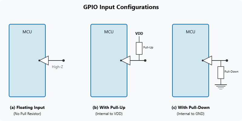
Why use them? Consider a button connected between a GPIO input pin and Ground.
- Without any pull resistor, when the button is not pressed, the pin is floating.
- With an internal pull-up resistor enabled, when the button is not pressed, the pin reads High (Logic ‘1’). When the button is pressed, it connects the pin directly to Ground, overriding the pull-up and making the pin read Low (Logic ‘0’). This provides a clear distinction between the pressed and not-pressed states.
ESP-IDF allows enabling/disabling these internal pull resistors programmatically for input pins.
Tip: It’s almost always necessary to enable either a pull-up or pull-down resistor on a GPIO configured as an input, unless you are certain the external circuitry will always actively drive the pin High or Low. Pull-ups are very common for buttons connected to ground.
Open-Drain Output Mode
Standard output mode (often called “push-pull”) actively drives the pin High or Low. Open-Drain mode is a special output configuration where the pin can actively drive the signal Low, but it cannot actively drive it High. Instead, when set to output ‘1’, the pin effectively disconnects its output driver and goes into a high-impedance state (like an input).
To achieve a High signal in open-drain mode, an external pull-up resistor is required.
| Feature | Push-Pull Output (Standard) | Open-Drain Output |
|---|---|---|
| Driving High (Logic ‘1’) | Actively drives the pin to VCC (e.g., 3.3V). Sources current. | Does not actively drive High. Pin goes to high-impedance state. Requires an external pull-up resistor to achieve a High level. |
| Driving Low (Logic ‘0’) | Actively drives the pin to GND (0V). Sinks current. | Actively drives the pin to GND (0V). Sinks current. |
| External Pull-up for High Level | Not required for normal operation (though can be used for specific interface needs). | Required to achieve a logic High state on the line. |
| Multiple Outputs on Same Line | Generally problematic if multiple push-pull outputs are connected directly and try to drive different levels (can cause shorts or contention). | Allows multiple open-drain outputs to be connected to the same line (wired-AND configuration). If any output drives Low, the line goes Low. Line is High only if all outputs are in high-impedance state. |
| Power Consumption | May consume more power when driving High due to active transistor. | May consume less power from the chip itself when “outputting” High (as it’s high-impedance), but power is consumed by the external pull-up resistor. |
| Common Use Cases | Driving LEDs, general digital signaling to single devices, SPI/UART signals (typically). | I2C bus (SDA/SCL lines), shared interrupt lines, level shifting (with careful design), creating wired-AND logic. |
| ESP-IDF Mode Value | GPIO_MODE_OUTPUT |
GPIO_MODE_OUTPUT_OD |
Use Cases:
- Wired-AND Logic: Multiple open-drain outputs can be connected to the same wire with a single pull-up resistor. The wire will be High only if all outputs are in their high-impedance state (outputting ‘1’). If any output drives Low, the entire wire goes Low.
- Level Shifting: Can sometimes be used in interfacing circuits operating at different voltage levels (with careful design).
- I2C Bus: The I2C communication protocol relies on open-drain outputs for both SDA (data) and SCL (clock) lines, allowing multiple devices to share the bus.
Drive Strength
When a GPIO is configured as an output, it needs to source current (when driving High) or sink current (when driving Low) to the connected load (e.g., an LED and its series resistor). The Drive Strength setting determines the maximum current the pin can reliably source or sink without its voltage level dropping (for High) or rising (for Low) significantly.
ESP-IDF allows configuring the drive strength for output pins (e.g., 5mA, 10mA, 20mA, 40mA – exact values depend on the ESP32 variant).
- Low Drive Strength: Consumes less power during switching, generates less electromagnetic interference (EMI). Suitable for driving high-impedance inputs or low-current loads.
- High Drive Strength: Can source/sink more current, suitable for driving LEDs directly (with appropriate series resistors!), or ensuring faster signal transitions on longer traces or capacitive loads. Consumes more power and generates more noise.
Warning: Never exceed the maximum current rating specified in the ESP32 datasheet for a GPIO pin, regardless of the drive strength setting. Always use current-limiting resistors for LEDs. Setting drive strength too high for a load that doesn’t require it wastes power.
IO MUX and GPIO Matrix
Modern microcontrollers like the ESP32 have many internal peripherals (UART, SPI, I2C, Timers, ADC, etc.) that need to connect to the physical pins of the chip. Instead of having fixed pins for every single peripheral function (which would require an enormous number of pins), the ESP32 uses a flexible routing system:
- IO MUX (Input/Output Multiplexer): Each physical pin has a primary peripheral function assigned to it by default (e.g., a specific pin might default to being TXD0 for UART0). The IO MUX allows selecting this primary function.
- GPIO Matrix: Provides a more powerful, crossbar-like switch. It allows routing almost any internal peripheral signal (input or output) to almost any GPIO pin, overriding the default IO MUX function if necessary. It also routes simple GPIO input/output signals when a pin is configured for basic GPIO use.
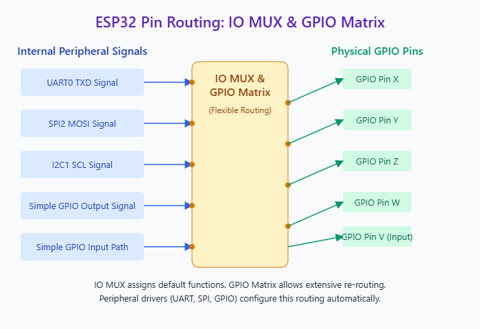
This flexibility means you often don’t need to worry about which specific pin is “the” SPI CLK pin; you can usually configure any suitable GPIO pin for that role using the GPIO Matrix (configured automatically by the peripheral drivers like SPI or I2C). When using a pin for simple digital input/output, you are configuring the GPIO Matrix to connect the pin to the internal GPIO read/write registers.
RTC IO
As mentioned in Chapter 19, certain GPIO pins are connected to the RTC power domain. These RTC GPIOs can be controlled by the RTC controller even during deep sleep and can be used as wakeup sources. They have separate configuration functions (rtc_gpio_...) when used for deep sleep wakeup or ULP control. However, when the chip is active, these pins can also be used as regular digital GPIOs configured via the standard gpio_... functions described below. You only need the rtc_gpio_ functions when dealing with deep sleep or ULP functionality.
ESP-IDF GPIO Driver API (driver/gpio.h)
The primary API for configuring and controlling GPIO pins in ESP-IDF is found in the driver/gpio.h header file.
| Function Name | Purpose | Key Parameters | Returns |
|---|---|---|---|
gpio_config(const gpio_config_t *pGPIOConfig) |
Configures one or more GPIO pins based on the settings in the provided gpio_config_t structure. |
pGPIOConfig: Pointer to gpio_config_t structure. |
esp_err_t (ESP_OK on success) |
gpio_set_level(gpio_num_t gpio_num, uint32_t level) |
Sets the output logic level of a specified GPIO pin. | gpio_num: The GPIO number.level: 0 for Low, 1 (or non-zero) for High. |
esp_err_t |
gpio_get_level(gpio_num_t gpio_num) |
Reads the current logic level of a specified GPIO input pin. | gpio_num: The GPIO number. |
int (0 for Low, 1 for High) |
gpio_set_direction(gpio_num_t gpio_num, gpio_mode_t mode) |
Sets the direction (mode) for a single GPIO pin. | gpio_num: The GPIO number.mode: GPIO_MODE_INPUT, GPIO_MODE_OUTPUT, etc. |
esp_err_t |
gpio_set_pull_mode(gpio_num_t gpio_num, gpio_pull_mode_t pull) |
Sets the pull-up/pull-down mode for a single GPIO pin. | gpio_num: The GPIO number.pull: GPIO_PULLUP_ONLY, GPIO_PULLDOWN_ONLY, GPIO_PULLUP_PULLDOWN, GPIO_FLOATING. |
esp_err_t |
gpio_pullup_en(gpio_num_t gpio_num) / dis(gpio_num_t gpio_num) |
Enables/disables the internal pull-up resistor for a single GPIO. | gpio_num: The GPIO number. |
esp_err_t |
gpio_pulldown_en(gpio_num_t gpio_num) / dis(gpio_num_t gpio_num) |
Enables/disables the internal pull-down resistor for a single GPIO. | gpio_num: The GPIO number. |
esp_err_t |
gpio_set_drive_capability(gpio_num_t gpio_num, gpio_drive_cap_t strength) |
Sets the output drive strength for a single GPIO pin. | gpio_num: The GPIO number.strength: GPIO_DRIVE_CAP_0 to GPIO_DRIVE_CAP_3 (or _MAX/_DEFAULT). |
esp_err_t |
gpio_reset_pin(gpio_num_t gpio_num) |
Resets a GPIO to its default state (input, floating, low drive strength, interrupts disabled). | gpio_num: The GPIO number. |
esp_err_t |
1. Configuration Structure: gpio_config_t
Most GPIO configuration is done using the gpio_config_t structure, which is then passed to the gpio_config() function.
typedef struct {
    uint64_t pin_bit_mask;      /*!< GPIO pin: set the bit mask of the pins to be configured, e.g. (1ULL<<GPIO_NUM_1) | (1ULL<<GPIO_NUM_2) */
    gpio_mode_t mode;           /*!< GPIO mode: set input / output / open-drain / output+open-drain */
    gpio_pullup_t pull_up_en;   /*!< GPIO pull-up */
    gpio_pulldown_t pull_down_en; /*!< GPIO pull-down */
    gpio_int_type_t intr_type;  /*!< GPIO interrupt type */
} gpio_config_t;
pin_bit_mask: A 64-bit mask indicating which GPIO pin(s) this configuration applies to. Use(1ULL << GPIO_NUM_X)for a single pin or combine multiple pins with the bitwise OR operator (|). Example:(1ULL << GPIO_NUM_4) | (1ULL << GPIO_NUM_5).mode: Sets the pin direction and type:GPIO_MODE_DISABLE: Disable GPIO (default).GPIO_MODE_INPUT: Input mode.GPIO_MODE_OUTPUT: Output mode (push-pull).GPIO_MODE_OUTPUT_OD: Output mode (open-drain).GPIO_MODE_INPUT_OUTPUT_OD: Input + Output Open-Drain (bidirectional).GPIO_MODE_INPUT_OUTPUT: Input + Output Push-Pull (bidirectional).
pull_up_en: Enable (GPIO_PULLUP_ENABLE) or disable (GPIO_PULLUP_DISABLE) the internal pull-up resistor. Only effective in input or open-drain modes.pull_down_en: Enable (GPIO_PULLDOWN_ENABLE) or disable (GPIO_PULLDOWN_DISABLE) the internal pull-down resistor. Only effective in input or open-drain modes.intr_type: Configures the interrupt trigger type (e.g.,GPIO_INTR_POSEDGE,GPIO_INTR_NEGEDGE,GPIO_INTR_ANYEDGE,GPIO_INTR_LOW_LEVEL,GPIO_INTR_HIGH_LEVEL,GPIO_INTR_DISABLE). Covered in detail in Chapter 17. Set toGPIO_INTR_DISABLEif not using interrupts.
| Member Name | Data Type | Description & Example Values |
|---|---|---|
pin_bit_mask |
uint64_t |
A bitmask specifying the GPIO pin(s) to configure. Each bit corresponds to a GPIO number. Example: (1ULL << GPIO_NUM_4) for GPIO4, or (1ULL << GPIO_NUM_4) | (1ULL << GPIO_NUM_5) for GPIO4 and GPIO5. |
mode |
gpio_mode_t (enum) |
Sets the GPIO direction and type. Values: GPIO_MODE_DISABLE, GPIO_MODE_INPUT, GPIO_MODE_OUTPUT, GPIO_MODE_OUTPUT_OD, GPIO_MODE_INPUT_OUTPUT, GPIO_MODE_INPUT_OUTPUT_OD. |
pull_up_en |
gpio_pullup_t (enum) |
Enables or disables the internal pull-up resistor. Values: GPIO_PULLUP_ENABLE, GPIO_PULLUP_DISABLE.Effective for input or open-drain output modes. |
pull_down_en |
gpio_pulldown_t (enum) |
Enables or disables the internal pull-down resistor. Values: GPIO_PULLDOWN_ENABLE, GPIO_PULLDOWN_DISABLE.Effective for input or open-drain output modes. |
intr_type |
gpio_int_type_t (enum) |
Configures the interrupt trigger type for the pin(s). Values: GPIO_INTR_DISABLE (default), GPIO_INTR_POSEDGE, GPIO_INTR_NEGEDGE, GPIO_INTR_ANYEDGE, GPIO_INTR_LOW_LEVEL, GPIO_INTR_HIGH_LEVEL.(Interrupts covered in Chapter 17). |
2. Applying Configuration: gpio_config()
esp_err_t gpio_config(const gpio_config_t *pGPIOConfig);
- Applies the settings defined in the
gpio_config_tstructure pointed to bypGPIOConfigto the pins specified in thepin_bit_mask. - Returns
ESP_OKon success, or an error code on failure.
3. Setting Output Level: gpio_set_level()
esp_err_t gpio_set_level(gpio_num_t gpio_num, uint32_t level);
- Sets the output level of the specified
gpio_num. level:0for Low,1(or any non-zero value) for High.- The pin must be configured as an output mode (
GPIO_MODE_OUTPUTorGPIO_MODE_OUTPUT_OD). - Returns
ESP_OKon success.
4. Getting Input Level: gpio_get_level()
int gpio_get_level(gpio_num_t gpio_num);
- Reads the current logic level of the specified
gpio_num. - The pin must be configured in an input-capable mode (
GPIO_MODE_INPUT,GPIO_MODE_INPUT_OUTPUT,GPIO_MODE_INPUT_OUTPUT_OD). - Returns
0if the pin is Low,1if the pin is High.
5. Setting Direction: gpio_set_direction()
esp_err_t gpio_set_direction(gpio_num_t gpio_num, gpio_mode_t mode);
- Sets the direction (
mode) for a singlegpio_num. Simpler alternative togpio_configfor changing only the direction. - Returns
ESP_OKon success.
6. Setting Pull Mode: gpio_set_pull_mode(), gpio_pullup_en(), gpio_pullup_dis(), gpio_pulldown_en(), gpio_pulldown_dis()
esp_err_t gpio_set_pull_mode(gpio_num_t gpio_num, gpio_pull_mode_t pull); // pull: GPIO_PULLUP_ONLY, GPIO_PULLDOWN_ONLY, GPIO_PULLUP_PULLDOWN, GPIO_FLOATING
esp_err_t gpio_pullup_en(gpio_num_t gpio_num);
esp_err_t gpio_pullup_dis(gpio_num_t gpio_num);
esp_err_t gpio_pulldown_en(gpio_num_t gpio_num);
esp_err_t gpio_pulldown_dis(gpio_num_t gpio_num);
- Functions to configure pull-up/down resistors for a single
gpio_num. Simpler alternatives togpio_configfor changing only pull modes. - Return
ESP_OKon success.
7. Setting Drive Strength: gpio_set_drive_capability()
esp_err_t gpio_set_drive_capability(gpio_num_t gpio_num, gpio_drive_cap_t strength);
- Sets the output drive strength for a single
gpio_num. strength: An enum value likeGPIO_DRIVE_CAP_0(lowest, ~5mA),GPIO_DRIVE_CAP_1(~10mA),GPIO_DRIVE_CAP_2(~20mA),GPIO_DRIVE_CAP_3(highest, ~40mA).GPIO_DRIVE_CAP_DEFAULTusually corresponds toGPIO_DRIVE_CAP_2. (Exact currents and enum mapping can vary slightly by chip - checkgpio_drive_cap_tdefinition and datasheets).- Returns
ESP_OKon success.
Practical Examples
Project Setup:
Follow the standard project setup (copy hello_world, open in VS Code). You might need an LED, a current-limiting resistor (e.g., 220-330 Ohm), and a pushbutton switch for these examples.
Common Includes and Setup:
Add/ensure these includes are at the top of your main/your_main_file.c:
#include <stdio.h>
#include "freertos/FreeRTOS.h"
#include "freertos/task.h"
#include "driver/gpio.h"
#include "esp_log.h"

static const char *TAG = "GPIO_EXAMPLE";

// Define GPIOs used in examples
#define BLINK_GPIO GPIO_NUM_2  // Example: GPIO for LED output
#define BUTTON_GPIO GPIO_NUM_4 // Example: GPIO for Button input
Example 1: Blinking an LED (Basic Output)
Connect an LED and series resistor between BLINK_GPIO and GND.
void app_main(void) {
    ESP_LOGI(TAG, "Starting LED Blink Example...");

    // --- Configure the GPIO ---
    gpio_config_t io_conf;
    // Disable interrupt
    io_conf.intr_type = GPIO_INTR_DISABLE;
    // Set as output mode
    io_conf.mode = GPIO_MODE_OUTPUT;
    // Bit mask of the pins that you want to set, e.g.GPIO2
    io_conf.pin_bit_mask = (1ULL << BLINK_GPIO);
    // Disable pull-down mode
    io_conf.pull_down_en = GPIO_PULLDOWN_DISABLE;
    // Disable pull-up mode
    io_conf.pull_up_en = GPIO_PULLUP_DISABLE;
    // Configure GPIO with the given settings
    esp_err_t config_result = gpio_config(&io_conf);
    if (config_result != ESP_OK) {
         ESP_LOGE(TAG, "GPIO config failed: %s", esp_err_to_name(config_result));
         return;
    }

    ESP_LOGI(TAG, "GPIO %d configured as output. Starting blink.", BLINK_GPIO);

    bool led_state = false;
    while(1) {
        led_state = !led_state; // Toggle state
        ESP_LOGD(TAG, "Turning LED %s", led_state ? "ON" : "OFF");

        // Set GPIO level
        gpio_set_level(BLINK_GPIO, led_state ? 1 : 0);

        // Wait for half a second
        vTaskDelay(pdMS_TO_TICKS(500));
    }
}
Build, Flash, and Monitor:
Standard procedure.
Expected Output:
The LED connected to BLINK_GPIO should blink on and off every half second. The debug logs (if enabled) will show the state changes.
Example 2: Reading a Button (Input with Pull-up)
Connect a pushbutton switch between BUTTON_GPIO and GND.
void app_main(void) {
    ESP_LOGI(TAG, "Starting Button Read Example...");

    // --- Configure the GPIO ---
    gpio_config_t io_conf = {}; // Initialize to zero
    // Disable interrupt
    io_conf.intr_type = GPIO_INTR_DISABLE;
    // Set as input mode
    io_conf.mode = GPIO_MODE_INPUT;
    // Bit mask of the pins, use GPIO4 here
    io_conf.pin_bit_mask = (1ULL << BUTTON_GPIO);
    // Enable internal pull-up resistor
    io_conf.pull_up_en = GPIO_PULLUP_ENABLE;
    // Disable pull-down resistor
    io_conf.pull_down_en = GPIO_PULLDOWN_DISABLE;
    // Configure GPIO with the given settings
    esp_err_t config_result = gpio_config(&io_conf);
     if (config_result != ESP_OK) {
         ESP_LOGE(TAG, "GPIO config failed: %s", esp_err_to_name(config_result));
         return;
    }

    ESP_LOGI(TAG, "GPIO %d configured as input with pull-up.", BUTTON_GPIO);
    ESP_LOGI(TAG, "Press the button connected to GPIO %d (connects to GND).", BUTTON_GPIO);

    int last_level = 1; // Assume button is initially not pressed (pulled high)
    while(1) {
        // Read GPIO level
        int current_level = gpio_get_level(BUTTON_GPIO);

        // Print state only if it changes
        if (current_level != last_level) {
             ESP_LOGI(TAG, "Button state changed! GPIO %d level: %d", BUTTON_GPIO, current_level);
             if (current_level == 0) {
                 ESP_LOGI(TAG, "Button PRESSED");
             } else {
                 ESP_LOGI(TAG, "Button RELEASED");
             }
             last_level = current_level;
        }

        // Wait briefly before checking again (polling)
        vTaskDelay(pdMS_TO_TICKS(50)); // Check every 50ms
    }
}
Build, Flash, and Monitor:
Standard procedure.
Expected Output:
Initially, the log will show nothing (or maybe a single "Button RELEASED" if the initial state is logged). When you press the button, the log will show level: 0 and "Button PRESSED". When you release it, the log will show level: 1 and "Button RELEASED".
Example 3: Configuring Drive Strength (Conceptual)
This example shows how to set drive strength but doesn't visually demonstrate the effect without measuring current or signal integrity.
void app_main(void) {
    ESP_LOGI(TAG, "Starting Drive Strength Example (Conceptual)...");

    // --- Configure the GPIO as output (similar to Example 1) ---
    gpio_config_t io_conf = {};
    io_conf.intr_type = GPIO_INTR_DISABLE;
    io_conf.mode = GPIO_MODE_OUTPUT;
    io_conf.pin_bit_mask = (1ULL << BLINK_GPIO);
    io_conf.pull_down_en = GPIO_PULLDOWN_DISABLE;
    io_conf.pull_up_en = GPIO_PULLUP_DISABLE;
    gpio_config(&io_conf);

    ESP_LOGI(TAG, "GPIO %d configured as output.", BLINK_GPIO);

    // --- Set Drive Strength ---
    // Try different capabilities, e.g., weakest and strongest
    ESP_LOGI(TAG, "Setting drive strength to LOW (~5mA)...");
    esp_err_t ds_err1 = gpio_set_drive_capability(BLINK_GPIO, GPIO_DRIVE_CAP_0);
    if (ds_err1 != ESP_OK) ESP_LOGE(TAG, "Failed to set drive cap 0: %s", esp_err_to_name(ds_err1));

    // Toggle LED (or just set level high)
    gpio_set_level(BLINK_GPIO, 1);
    vTaskDelay(pdMS_TO_TICKS(2000)); // Wait 2 seconds

    ESP_LOGI(TAG, "Setting drive strength to HIGH (~40mA)...");
    esp_err_t ds_err2 = gpio_set_drive_capability(BLINK_GPIO, GPIO_DRIVE_CAP_3); // Or GPIO_DRIVE_CAP_MAX
     if (ds_err2 != ESP_OK) ESP_LOGE(TAG, "Failed to set drive cap 3: %s", esp_err_to_name(ds_err2));

    // Toggle LED (or just set level low)
    gpio_set_level(BLINK_GPIO, 0);
    vTaskDelay(pdMS_TO_TICKS(2000)); // Wait 2 seconds

    ESP_LOGI(TAG, "Setting drive strength back to DEFAULT (~20mA)...");
    esp_err_t ds_err3 = gpio_set_drive_capability(BLINK_GPIO, GPIO_DRIVE_CAP_DEFAULT);
     if (ds_err3 != ESP_OK) ESP_LOGE(TAG, "Failed to set drive cap default: %s", esp_err_to_name(ds_err3));

    gpio_set_level(BLINK_GPIO, 1);
    ESP_LOGI(TAG, "Drive Strength Example Finished.");

    while(1) { vTaskDelay(portMAX_DELAY); } // Idle
}
Build, Flash, and Monitor:
Standard procedure.
Expected Output:
The code will run and print logs indicating the drive strength changes. The LED brightness might change slightly if it's sensitive enough and the default drive strength wasn't already sufficient, but the main purpose here is to show the API usage.
Example 4: Configuring Open-Drain (Conceptual)
This example configures a pin as open-drain but requires an external pull-up resistor on that pin to see a High level.
#define OD_GPIO GPIO_NUM_18 // Example GPIO for Open-Drain

void app_main(void) {
    ESP_LOGI(TAG, "Starting Open-Drain Example (Conceptual)...");
    ESP_LOGI(TAG, "NOTE: Requires an EXTERNAL pull-up resistor on GPIO %d to VCC (e.g., 4.7kOhm).", OD_GPIO);

    // --- Configure the GPIO as Open-Drain Output ---
    gpio_config_t io_conf = {};
    io_conf.intr_type = GPIO_INTR_DISABLE;
    // Set as output open-drain mode
    io_conf.mode = GPIO_MODE_OUTPUT_OD;
    io_conf.pin_bit_mask = (1ULL << OD_GPIO);
    // Pull-up/down are disabled in OD output mode driver config,
    // rely on EXTERNAL pull-up.
    io_conf.pull_down_en = GPIO_PULLDOWN_DISABLE;
    io_conf.pull_up_en = GPIO_PULLUP_DISABLE;
    gpio_config(&io_conf);

    ESP_LOGI(TAG, "GPIO %d configured as Open-Drain output.", OD_GPIO);

    while(1) {
        ESP_LOGI(TAG, "Setting Open-Drain output LOW (Actively driving Low)...");
        gpio_set_level(OD_GPIO, 0);
        vTaskDelay(pdMS_TO_TICKS(3000)); // Wait 3 seconds

        ESP_LOGI(TAG, "Setting Open-Drain output HIGH (High Impedance - relies on external pull-up)...");
        gpio_set_level(OD_GPIO, 1);
        vTaskDelay(pdMS_TO_TICKS(3000)); // Wait 3 seconds
    }
}
Build, Flash, and Monitor:
Standard procedure. Crucially, connect an external pull-up resistor (e.g., 4.7kΩ or 10kΩ) between OD_GPIO and your 3.3V supply. You can monitor the pin's voltage with a multimeter or oscilloscope.
Expected Output:
The log messages will indicate the intended state. If you measure the voltage on OD_GPIO:
- When set to
0, the voltage should be near 0V (actively driven Low). - When set to
1, the voltage should be near 3.3V (pulled High by the external resistor). Without the external pull-up, the voltage would likely float or stay Low whengpio_set_level(OD_GPIO, 1)is called.
Variant Notes
- Number of GPIOs: This varies significantly. Original ESP32 has up to 40 pins (though some are used internally for Flash/RAM), ESP32-S2/S3 have more (~48), while ESP32-C3/C6/H2 have fewer (~22). Always check the datasheet for your specific chip/module.
- Pin Numbering: All variants use the
GPIO_NUM_Xenumeration. However, the maximum validXdiffers. The driver will return errors if you use an invalid GPIO number for your target. - RTC IO: The specific pins that double as RTC IOs (usable for deep sleep wakeup) differ between variants. Consult the datasheet's pin list.
rtc_gpio_is_valid_gpio()can check this programmatically. - Strapping Pins: Certain GPIO pins have a secondary function during chip reset (strapping pins). They determine boot modes (e.g., flashing mode, SPI flash voltage). Pulling these pins High or Low externally during boot can prevent normal operation if it conflicts with the intended boot mode. Common strapping pins include GPIO0, GPIO2, GPIO12 (MTDI), GPIO15 (MTDO) on various models, but always check the datasheet for your specific variant. Avoid using strapping pins for inputs that might be held High/Low during reset unless you understand the implications.
- Analog Functions: Some GPIO pins can also be configured for analog functions (ADC input, DAC output, Touch). Using a pin for GPIO disables its analog function and vice-versa. The available analog-capable pins vary.
- Internal Pull Resistors: The resistance value of internal pull-up/down resistors can vary slightly between variants (typically in the 30kΩ-50kΩ range).
- Drive Strength: The exact current values corresponding to
GPIO_DRIVE_CAP_Xlevels might differ slightly. Datasheets usually provide typical values.
Common Mistakes & Troubleshooting Tips
| Common Mistake / Pitfall | Potential Symptom(s) | Fix / Best Practice |
|---|---|---|
| Floating Inputs | gpio_get_level() returns random values (0 or 1) for an input pin that isn't externally driven. Unreliable button/switch readings. |
Enable internal pull-up (pull_up_en = GPIO_PULLUP_ENABLE) or pull-down (pull_down_en = GPIO_PULLDOWN_ENABLE) resistor in gpio_config_t, or use external pull resistors. Choose based on circuit logic (pull-up is common for buttons to GND). |
| Incorrect Mode Configuration | Trying to gpio_set_level() on an input pin, or gpio_get_level() on an output-only pin. Functions may return errors or have no effect. |
Ensure gpio_config_t::mode (or gpio_set_direction()) is set correctly for the intended operation (e.g., GPIO_MODE_INPUT for reading, GPIO_MODE_OUTPUT for writing). |
| Exceeding Drive Strength / No Current Limiting | LED burns out, GPIO pin damaged, ESP32 resets or behaves erratically due to voltage droop or excessive current. | Always use a series current-limiting resistor with LEDs. For higher current loads, use the GPIO to control a transistor (MOSFET, BJT). Respect datasheet current limits and configure appropriate drive strength. |
| Strapping Pin Conflicts | Device fails to boot normally, gets stuck in bootloader mode, or doesn't run application firmware. Works only if pin is manually held differently during reset. | Consult datasheet for your ESP32 variant's strapping pins. Avoid using them for inputs/outputs that might interfere with boot, or ensure the external circuit ensures correct boot state but can be overridden later by the application. |
| Incorrect Pin Number or Bitmask | gpio_config() or other functions return ESP_ERR_INVALID_ARG. Pin doesn't function. Using (1 << GPIO_NUM_X) instead of (1ULL << GPIO_NUM_X) for pins > 31. |
Verify GPIO number against datasheet/schematic. Use (1ULL << GPIO_NUM_X) for pin_bit_mask to support all GPIOs. |
| Not Checking Function Return Values | Configuration or operation silently fails, leading to unexpected behavior later. | Always check the esp_err_t return values of GPIO API functions (gpio_config, gpio_set_level, etc.) and handle errors appropriately. |
| Using RTC GPIO Functions for Regular GPIO Operations | Trying to use rtc_gpio_... functions when the chip is active and the pin is intended for general digital I/O, not deep sleep wakeup or ULP. |
Use standard gpio_... API for general digital I/O. Only use rtc_gpio_... functions for deep sleep related functionality or ULP control. |
| Misunderstanding Open-Drain Behavior | Pin doesn't go High when set to '1' in open-drain mode. | Remember that open-drain outputs require an external pull-up resistor to achieve a High level. The ESP32 only actively pulls Low or goes high-impedance. |
Exercises
- Knight Rider LEDs: Connect 4-6 LEDs (each with a series resistor) to consecutive GPIO pins. Write a program that illuminates them one by one back and forth, creating a "Knight Rider" effect.
- Multiple Buttons: Connect two buttons to two different input GPIO pins (using internal pull-ups). Write a program that reads both buttons and prints a message indicating which button (or both, or neither) is currently pressed.
- Button-Controlled LED: Combine the previous exercises. Make one button turn an LED on, and the second button turn the same LED off.
- Pull Mode Experiment: Configure a GPIO pin as input. Use
gpio_set_pull_mode()to cycle throughGPIO_FLOATING,GPIO_PULLUP_ONLY, andGPIO_PULLDOWN_ONLY. In each mode, read the pin's state usinggpio_get_level()(without anything connected externally) and print the result. Observe how the pull resistors affect the default reading. - Strapping Pin Research: Choose a specific ESP32 variant (e.g., ESP32-C3). Find its datasheet on the Espressif website. Identify the strapping pins listed in the datasheet and briefly describe the function or boot mode associated with the state of each strapping pin during reset.
Summary
- GPIO pins are the primary digital interface between the ESP32 and external components.
- Pins can be configured as Input (read voltage level) or Output (set voltage level).
- Pull-up/Pull-down resistors (internal or external) are crucial for defining default states for inputs and preventing floating.
- Open-Drain output mode allows multiple outputs to share a wire (requires external pull-up).
- Drive Strength configures the current sourcing/sinking capability of output pins.
- The IO MUX and GPIO Matrix provide flexible routing of peripheral signals to physical pins.
- Use the
driver/gpio.hAPI, primarilygpio_config_tandgpio_config(), for setup. - Use
gpio_set_level()to write to outputs andgpio_get_level()to read from inputs. - GPIO pin availability, RTC capabilities, and strapping pin behavior vary across ESP32 variants. Always check the datasheet.
Further Reading
- ESP-IDF Programming Guide - GPIO: https://docs.espressif.com/projects/esp-idf/en/v5.4/esp32/api-reference/peripherals/gpio.html (Essential reference for API details).
- ESP-IDF Programming Guide - IO MUX and GPIO Matrix: https://docs.espressif.com/projects/esp-idf/en/v5.4/esp32/api-reference/peripherals/gpio_matrix.html
- ESP32 Series Datasheets: (Crucial for pinouts, strapping pins, electrical characteristics, RTC IO lists for your specific variant). Available on the Espressif website.
- ESP32 Technical Reference Manual: (For in-depth architectural details of the GPIO controller and IO MUX).
