
Chapter 183: DNP3 Protocol Basics with ESP-IDF
Chapter Objectives
After completing this chapter, you will be able to:
- Understand the purpose and significance of the DNP3 protocol in SCADA systems.
- Describe the DNP3 layered architecture and the function of each layer.
- Differentiate between DNP3 Master and Outstation (Slave) roles.
- Recognize common DNP3 data objects, function codes, and communication modes.
- Understand the general approach to implementing DNP3 on an ESP32 device.
- Identify potential challenges and considerations when working with DNP3 on resource-constrained devices.
- Appreciate the differences in implementing DNP3 across various ESP32 variants.
Introduction
Welcome to the world of industrial communication! In many Supervisory Control and Data Acquisition (SCADA) systems, particularly in sectors like electric utilities, water/wastewater management, and oil & gas, robust and reliable communication is paramount. The Distributed Network Protocol version 3 (DNP3) is a widely adopted protocol designed specifically for these environments. It facilitates communication between master stations (control centers) and outstations (remote terminal units – RTUs or intelligent electronic devices – IEDs).
While protocols like Modbus (covered in Chapters 176-180) are simpler, DNP3 offers more advanced features, such as unsolicited reporting by outstations, time-stamped data, and better data integrity. Understanding DNP3 basics is crucial if you plan to develop ESP32-based devices that need to integrate into these critical infrastructure systems. This chapter will lay the foundational knowledge for DNP3, preparing you for more complex implementations.
Theory
What is DNP3?
DNP3 (Distributed Network Protocol) is a set of communication protocols used between components in process automation systems. Its primary use is in utilities such as electric and water companies. It was developed for communications between various types of data acquisition and control equipment. DNP3 plays a crucial role in SCADA systems by enabling monitoring and control of remote devices over various communication channels (serial, IP networks).
The protocol is built upon a three-layer subset of the OSI seven-layer model, sometimes referred to as the Enhanced Performance Architecture (EPA). It is designed to be reliable even over unreliable media and can handle data fragmentation and reassembly.
DNP3 Layered Architecture
DNP3 uses a simplified model compared to the full OSI stack, focusing on efficiency and suitability for SCADA applications.
%%{init: {"theme": "base", "themeVariables": { "fontFamily": "Open Sans"}}}%%
graph TD
    subgraph User Application
        A[Application Data]
    end

    subgraph DNP3 Stack
        AppLayer[<b>Application Layer</b><br>APDU Fragments<br><i>Handles data objects, function codes</i>]
        TransportLayer{"Pseudo-Transport Layer<br><i>(Optional)</i><br>Segments/Reassembles APDUs"}
        LinkLayer[<b>Link Layer</b><br>LPDU Frames<br><i>Handles addressing, CRC, reliability</i>]
        PhysicalLayer["<b>Physical Layer</b><br>Electrical Signals<br><i>e.g., RS-485, Ethernet (TCP/IP)</i>"]
    end

    A -- Data to Send --> AppLayer
    AppLayer -- Message to Segment --> TransportLayer
    TransportLayer -- Segmented Data --> LinkLayer
    LinkLayer -- Frame to Transmit --> PhysicalLayer

    PhysicalLayer -- Received Frame --> LinkLayer
    LinkLayer -- Reassembled Data --> TransportLayer
    TransportLayer -- Full Message --> AppLayer
    AppLayer -- Interpreted Data --> A

    classDef default fill:#DBEAFE,stroke:#2563EB,stroke-width:1px,color:#1E40AF;
    classDef startNode fill:#EDE9FE,stroke:#5B21B6,stroke-width:2px,color:#5B21B6;
    classDef decisionNode fill:#FEF3C7,stroke:#D97706,stroke-width:1px,color:#92400E;

    class A startNode;
    class AppLayer,LinkLayer,PhysicalLayer default;
    class TransportLayer decisionNode;
- Physical Layer:
- Defines the physical medium for communication.
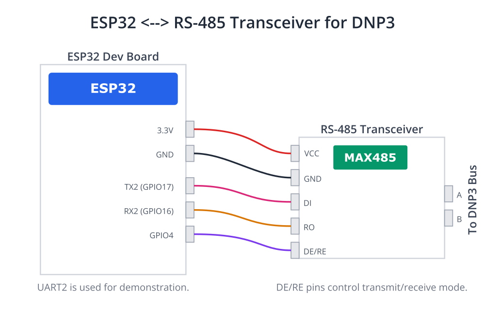
- Commonly, this is RS-485 for serial communication (see Chapter 181) or Ethernet for TCP/IP or UDP/IP communication.
- The ESP32 supports UART for RS-485 (via an external transceiver) and Wi-Fi/Ethernet for IP-based DNP3.
- Link Layer:
- Responsible for reliable data transfer between two directly connected devices.
- Handles addressing (source and destination DNP3 addresses), error detection (using CRC checksums), and frame synchronization.
- It ensures that frames are not lost, duplicated, or corrupted.
- Defines frame formats and procedures for establishing and maintaining a communication link.
- Supports both balanced (peer-to-peer) and unbalanced (master-slave) transmission procedures.
- Pseudo-Transport Layer (Optional but common):
- This is not a full transport layer in the OSI sense but provides a mechanism to segment large Application Layer messages into multiple Link Layer frames and reassemble them at the destination.
- It uses a single byte header to manage message segmentation and reassembly, ensuring that messages up to 2048 bytes can be transmitted.
- Application Layer:
- This is the core of DNP3, defining how data is structured and interpreted.
- It handles the exchange of data objects, commands, and responses.
- Application Layer messages are called Application Protocol Data Units (APDUs) or “fragments.”
- It defines:
- Function Codes: Specify the operation to be performed (e.g., Read, Write, Select, Operate, Direct Operate, Freeze, etc.).
- Object Groups and Variations: Define the type of data being exchanged (e.g., binary input, analog input, counter, binary output, analog output). Each object group can have multiple variations specifying data format, precision, and whether it includes timestamps or quality flags.
- Qualifiers and Range Fields: Used to specify which data points or how many data points are being requested or sent.
DNP3 Device Roles
DNP3 defines two primary device roles:
- Master (or Master Station):
- Typically a control center computer or a SCADA host.
- Initiates communication by polling outstations for data or sending commands.
- Collects data, issues control commands, and manages the network.
- An ESP32 could theoretically act as a DNP3 master in smaller systems, but it’s more common for it to be an outstation.
- Outstation (or Slave, Remote Terminal Unit – RTU, Intelligent Electronic Device – IED):
- A remote device that monitors and controls equipment in the field (e.g., sensors, actuators, circuit breakers).
- Responds to polls from the master, providing requested data.
- Can also send unsolicited messages (if configured) to report events or changes in data without waiting for a poll. This is a key feature of DNP3 for timely event reporting.
- ESP32 devices are well-suited to function as DNP3 outstations, collecting sensor data and controlling local processes.
%%{init: {"theme": "base", "themeVariables": { "fontFamily": "Open Sans"}}}%%
sequenceDiagram
    actor Master
    actor Outstation

    rect rgba(237, 233, 254, 0.5)
    Note over Master,Outstation: Polled Communication
        Master->>Outstation: Send READ Request (e.g., for Class 0 Data)
        activate Outstation
        Note right of Outstation: Outstation processes request,<br>retrieves static data values.
        Outstation-->>Master: Send RESPONSE with Data
        deactivate Outstation
    end

    rect rgba(219, 234, 254, 0.5)
    Note over Master,Outstation: Unsolicited Reporting
        Note over Outstation: An important event occurs!<br>(e.g., Binary input changes state)
        Outstation->>Master: Send UNSOLICITED RESPONSE with Event Data
        activate Master
        Note left of Master: Master receives and processes<br>the event data immediately.
        Master-->>Outstation: Acknowledge Unsolicited Response (if required)
        deactivate Master
    end
Data Objects and Object Variations
DNP3 organizes data into Object Groups. Each group represents a specific type of data. Within each group, there are Variations that define the format, size, and associated information (like timestamps or quality flags) for the data.
Common Object Groups include:
- Group 1: Binary Inputs (Read-only status)
- Variation 1: Status without time.
- Variation 2: Status with time.
- Group 2: Binary Input Events (Changes in binary inputs)
- Variation 1: Without time.
- Variation 2: With absolute time.
- Variation 3: With relative time (time delay).
- Group 10: Binary Outputs (Control relays)
- Variation 1: Control without time.
- Variation 2: Control with time.
- Group 12: Binary Output Status (Readback of output status)
- Group 20: Counters (Read-only)
- Group 22: Counter Events (Changes in counters)
- Group 30: Analog Inputs (Read-only measurements)
- Variation 1: 32-bit with flags.
- Variation 2: 16-bit with flags.
- Variation 5: 32-bit floating point with flags.
- Variation 6: 64-bit double precision floating point with flags.
- Group 32: Analog Input Events (Changes in analog inputs)
- Group 40: Analog Outputs (Control setpoints)
- Group 41: Analog Output Status (Readback of analog output status)
- Group 50: Time and Date Objects (For time synchronization)
- Group 60: Class Objects (For organizing data polling by class)
- Class 0: Static data (polled regularly).
- Class 1, 2, 3: Event data (polled or sent unsolicitedly based on priority).
| Object Group | Group Number(s) | Description | Primary Use |
|---|---|---|---|
| Binary Inputs | 1, 2 | Represents a single-bit digital status (On/Off, Open/Closed). Group 1 is for static status, Group 2 is for event changes. | Reading switch status, alarms, valve positions. |
| Binary Outputs | 10, 12 | Represents a controllable single-bit digital point. Group 10 is for control commands, Group 12 is for reading back the output status. | Controlling relays, motors, lights. |
| Counters | 20, 22 | Represents a running count of events or accumulated values. Group 20 is for static values, Group 22 is for event changes. | Pulse counting, energy totalization, flow accumulation. |
| Analog Inputs | 30, 32 | Represents a variable analog measurement. Group 30 is for static values, Group 32 is for event changes (e.g., deadband exceeded). | Reading temperature, pressure, voltage, current. |
| Analog Outputs | 40, 41 | Represents a controllable analog setpoint. Group 40 is for control commands, Group 41 is for reading back the output status. | Setting motor speed, valve position, brightness level. |
| Time and Date | 50 | Used for time synchronization. Contains information about the current time and date. | Synchronizing outstation clocks with the master. |
| Class Objects | 60 | Used to group data points into classes (0, 1, 2, 3) for efficient polling. Class 0 is for static data, Classes 1-3 are for prioritized events. | Organizing data for integrity and event polls. |
Each data point in an outstation is identified by its Object Group, Variation, and an Index number.
Function Codes
Function codes tell the receiving device what action to perform or what type of message is being sent.
Key Function Codes:
| Code (Hex) | Name | Direction | Description |
|---|---|---|---|
| 0x01 | READ | Master → Outstation | Requests the values of specified data objects. |
| 0x02 | WRITE | Master → Outstation | Writes values to specified data objects. |
| 0x03 | SELECT | Master → Outstation | Prepares a control object for operation (Select-Before-Operate). |
| 0x04 | OPERATE | Master → Outstation | Executes the previously selected control operation. |
| 0x05 | DIRECT_OPERATE | Master → Outstation | Performs a control operation immediately without a prior SELECT. |
| 0x20 | ENABLE_UNSOLICITED | Master → Outstation | Permits the outstation to send unsolicited responses. |
| 0x21 | DISABLE_UNSOLICITED | Master → Outstation | Forbids the outstation from sending unsolicited responses. |
| 0x81 | RESPONSE | Outstation → Master | The normal response to a master’s request. Contains data or confirmations. |
| 0x82 | UNSOLICITED_RESPONSE | Outstation → Master | A spontaneous message reporting events, not prompted by a specific request. |
Communication Modes
- Polled Mode:
- The master periodically requests data from outstations.
- Integrity Poll: A request for all static data (typically Class 0 data and sometimes Class 1, 2, 3 event data if not cleared by other polls).
- Event Poll: A request for event data (Class 1, 2, or 3).
- Unsolicited Reporting Mode:
- Outstations can send data to the master without being polled if significant events occur (e.g., a binary input changes state, an analog input exceeds a deadband).
- This reduces network traffic and provides faster updates for critical events.
- The master must enable unsolicited messaging for this to occur.
Time Synchronization
Accurate time stamping of events is critical in SCADA systems for sequence-of-events analysis. DNP3 includes mechanisms for time synchronization.
Masters can send time objects (Group 50) to outstations to set or adjust their internal clocks. Outstations can then timestamp event data with high precision.
DNP3 Secure Authentication (SA)
To address cybersecurity concerns, DNP3 Secure Authentication (DNP3 SA) was developed. It provides a mechanism to authenticate DNP3 messages, ensuring they originate from a trusted source and have not been tampered with.
DNP3 SA involves challenges, session keys, and message authentication codes (MACs). Implementing DNP3 SA adds complexity but is crucial for secure systems.
Tip: The DNP3 protocol is extensively documented by the DNP Users Group. Their website is an invaluable resource for detailed specifications.
Practical Examples
Implementing a full DNP3 stack (master or outstation) on an ESP32 from scratch is a significant undertaking due to the protocol’s complexity. ESP-IDF does not include a native DNP3 library. Therefore, you would typically rely on third-party open-source or commercial DNP3 libraries. One popular open-source option is OpenDNP3.
The general steps to integrate a third-party DNP3 library into an ESP-IDF project would involve:
- Choosing a Library: Select a DNP3 library written in C or C++ that is suitable for embedded systems (consider memory footprint, portability, and license).
- Creating an ESP-IDF Component: Package the library as an ESP-IDF component. This involves creating a
CMakeLists.txtfile for the library and placing the source code in thecomponentsdirectory of your ESP-IDF project. - Platform Abstraction: The library might require a platform abstraction layer (PAL) for things like timers, mutexes, serial I/O, or TCP/IP socket communication. You would implement this PAL using ESP-IDF APIs (FreeRTOS for threading/timers, LwIP for TCP/IP, UART driver for serial).
- Application Logic: Write your application code to:
- Initialize the DNP3 stack.
- Configure DNP3 parameters (addresses, port settings, etc.).
- Define the outstation’s data point map (mapping physical I/O or internal variables to DNP3 object/index points).
- Handle callbacks or interfaces provided by the library for data reads, command execution, and time synchronization.
Conceptual Code Snippet (Hypothetical Outstation Initialization)
Below is a conceptual C code snippet illustrating how you might initialize and run a DNP3 outstation task using a hypothetical DNP3 library. This is not directly compilable without an actual library and its specific API.
#include "freertos/FreeRTOS.h"
#include "freertos/task.h"
#include "esp_log.h"
#include "esp_system.h"

// Hypothetical DNP3 library headers
// #include "dnp3_stack.h"
// #include "dnp3_outstation_config.h"
// #include "dnp3_port_serial.h" // Or dnp3_port_tcp.h

static const char *TAG = "dnp3_app";

// --- Hypothetical DNP3 Library Callback Implementations ---
// These functions would be called by the DNP3 stack to interact with your hardware/data.

// Example: Read a binary input status
// bool app_read_binary_input(uint16_t index, bool *value, uint8_t *flags) {
//     ESP_LOGI(TAG, "DNP3 Stack requests Binary Input index %u", index);
//     // TODO: Read actual hardware input based on index
//     if (index == 0) {
//         *value = true; // Example value
//         *flags = 0x01; // Online
//         return true;
//     }
//     return false; // Index not found
// }

// Example: Operate a binary output
// bool app_operate_binary_output(uint16_t index, uint8_t op_type, bool *value, uint8_t *flags) {
//     ESP_LOGI(TAG, "DNP3 Stack requests Binary Output index %u, OpType: %u", index, op_type);
//     // TODO: Control actual hardware output based on index and op_type
//     // (e.g., LATCH_ON, LATCH_OFF, PULSE_ON, PULSE_OFF)
//     if (index == 0) {
//         // Simulate setting the output
//         ESP_LOGI(TAG, "Operating binary output %u", index);
//         *value = true; // Reflect new state
//         *flags = 0x01; // Online
//         return true;
//     }
//     return false;
// }


void dnp3_outstation_task(void *pvParameters) {
    ESP_LOGI(TAG, "DNP3 Outstation Task Started.");

    // --- Hypothetical DNP3 Stack Initialization ---
    // dnp3_outstation_config_t config;
    // dnp3_stack_init_outstation_config(&config);

    // config.link_layer.local_address = 10;   // DNP3 Outstation Address
    // config.link_layer.remote_address = 1;   // DNP3 Master Address
    // config.app_layer.enable_unsolicited = true;
    // config.app_layer.default_event_class_1_variation = /* ... */;

    // // Configure communication port (e.g., Serial)
    // dnp3_serial_port_config_t serial_config;
    // serial_config.uart_num = UART_NUM_2;
    // serial_config.baud_rate = 19200;
    // serial_config.rx_pin = GPIO_NUM_16;
    // serial_config.tx_pin = GPIO_NUM_17;
    // // For RS485, you might need an RTS pin for direction control
    // // serial_config.rts_pin = GPIO_NUM_4;

    // void* dnp3_port = dnp3_serial_port_create(&serial_config);
    // if (!dnp3_port) {
    //     ESP_LOGE(TAG, "Failed to create DNP3 serial port.");
    //     vTaskDelete(NULL);
    //     return;
    // }

    // // Create DNP3 outstation instance
    // dnp3_outstation_t* outstation = dnp3_outstation_create(&config, dnp3_port);
    // if (!outstation) {
    //     ESP_LOGE(TAG, "Failed to create DNP3 outstation instance.");
    //     // dnp3_serial_port_destroy(dnp3_port);
    //     vTaskDelete(NULL);
    //     return;
    // }

    // --- Register Application Callbacks (Hypothetical) ---
    // dnp3_outstation_set_read_binary_input_handler(outstation, app_read_binary_input);
    // dnp3_outstation_set_operate_binary_output_handler(outstation, app_operate_binary_output);
    // ... register other handlers for analog inputs, counters, etc. ...

    // --- Add Data Points to the Outstation's Database (Hypothetical) ---
    // dnp3_outstation_add_binary_input(outstation, 0, CLASS_1_EVENT, /* initial_value */ false, /* initial_flags */ 0x01);
    // dnp3_outstation_add_analog_input(outstation, 0, CLASS_1_EVENT, /* initial_value */ 0.0f, /* initial_flags */ 0x01);
    // dnp3_outstation_add_binary_output(outstation, 0, /* initial_value */ false, /* initial_flags */ 0x01);

    // --- Start the DNP3 Stack (Hypothetical) ---
    // if (!dnp3_outstation_start(outstation)) {
    //     ESP_LOGE(TAG, "Failed to start DNP3 outstation.");
    // } else {
    //     ESP_LOGI(TAG, "DNP3 Outstation started successfully.");
    // }

    // Main loop for the task. The DNP3 stack might run its own internal threads/tasks
    // or require periodic polling depending on its design.
    // This task could also be responsible for updating DNP3 point values from sensors.
    while (1) {
        // Example: Update an analog input point value periodically
        // float current_sensor_value = read_sensor_value(); // Your function
        // dnp3_outstation_update_analog_input(outstation, 0, current_sensor_value, 0x01 /* Online */);

        // The DNP3 stack might have a function to call periodically if it's not fully event-driven
        // dnp3_stack_process_events();

        vTaskDelay(pdMS_TO_TICKS(1000)); // Delay for 1 second
    }

    // --- Cleanup (Hypothetical) ---
    // dnp3_outstation_stop(outstation);
    // dnp3_outstation_destroy(outstation);
    // dnp3_serial_port_destroy(dnp3_port);
    // vTaskDelete(NULL);
}

void app_main(void) {
    // ... other initializations (NVS, Wi-Fi/Ethernet if DNP3 over IP) ...

    ESP_LOGI(TAG, "Creating DNP3 Outstation Task.");
    xTaskCreate(dnp3_outstation_task, "dnp3_outstation_task", 8192, NULL, 5, NULL); // Increased stack size
}
Build Instructions (General for Third-Party Library)
%%{init: {"theme": "base", "themeVariables": { "fontFamily": "Open Sans"}}}%%
graph TD
    A(<b>Start:</b><br>Select DNP3 Library) --> B{Create ESP-IDF Component};
    B --> C[Add Library Source Files];
    C --> D[Create Component <br>CMakeLists.txt];
    D --> E["Implement Platform <br>Abstraction Layer (PAL)"];
    subgraph PAL Implementation [Using ESP-IDF APIs]
        direction LR
        E_T(Timers<br><i>FreeRTOS</i>)
        E_S(Serial I/O<br><i>UART Driver</i>)
        E_N(Networking<br><i>LwIP Sockets</i>)
        E_M(Threading<br><i>Mutexes, Tasks</i>)
    end
    E --> E_T & E_S & E_N & E_M
    E_T & E_S & E_N & E_M --> F[Write Application Logic];
    F --> G{"Configure DNP3 Stack<br><i>(Addresses, Timings)</i>"};
    G --> H["Define Data Point Map<br><i>(Map HW to DNP3 objects)</i>"];
    H --> I["Register Application Callbacks<br><i>(Read/Write Handlers)</i>"];
    I --> J{"Build & Flash Project<br><i>(idf.py build flash)</i>"};
    J --> K(<b>End:</b><br>Test with Master Simulator);

    classDef startNode fill:#EDE9FE,stroke:#5B21B6,stroke-width:2px,color:#5B21B6;
    classDef processNode fill:#DBEAFE,stroke:#2563EB,stroke-width:1px,color:#1E40AF;
    classDef decisionNode fill:#FEF3C7,stroke:#D97706,stroke-width:1px,color:#92400E;
    classDef checkNode fill:#FEE2E2,stroke:#DC2626,stroke-width:1px,color:#991B1B;
    classDef endNode fill:#D1FAE5,stroke:#059669,stroke-width:2px,color:#065F46;

    class A startNode;
    class B,G,J decisionNode;
    class C,D,E,F,H,I processNode;
    class K endNode;
- Download/Obtain Library: Get the source code of the DNP3 library (e.g., clone OpenDNP3 or a fork suitable for embedded use).
- Create Component Directory: In your ESP-IDF project, create a directory
components/my_dnp3_library. - Add Library Source: Copy the library’s source files into this directory.
- Create
CMakeLists.txtfor the Component:# In components/my_dnp3_library/CMakeLists.txt idf_component_register(SRCS "source_file1.c" "source_file2.cpp" # List all source files INCLUDE_DIRS "include" # Path to library headers REQUIRES lwip # If using TCP/IP, for example # Add other dependencies if needed ) - Include in Project: Your main
CMakeLists.txtshould automatically pick up components from thecomponentsdirectory. - Configure Project: Use
idf.py menuconfigto set any project-specific options related to the library or your DNP3 application (e.g., UART pins, DNP3 addresses). - Build: Run
idf.py build.
Run/Flash/Observe Steps
- Flash: Use
idf.py -p (PORT) flash monitorto upload the firmware and view logs. - Setup DNP3 Master Simulator: Use a DNP3 master simulator software on a PC (e.g., Triangle Microworks Test Harness, AXON Test, or an open-source tool).
- Connect:
- Serial DNP3: Connect the ESP32’s UART (with an RS-485 transceiver if needed) to the PC’s serial port (or USB-to-Serial adapter).
- DNP3 over IP: Ensure the ESP32 is connected to the same network as the PC running the master simulator. Configure the master with the ESP32’s IP address and the DNP3 TCP/UDP port (typically 20000).
- Configure Master Simulator:
- Set the master and outstation DNP3 addresses to match your ESP32 configuration.
- Configure the communication parameters (baud rate for serial, IP/port for network).
- Define the data points you expect to read from or write to the ESP32 outstation.
- Observe:
- Use the master simulator to send polls (integrity, event) to the ESP32.
- Verify that the ESP32 responds with the correct data.
- Test control operations (e.g., writing to binary outputs).
- If unsolicited messaging is enabled, trigger events on the ESP32 (e.g., change a sensor input) and observe if unsolicited responses are sent to the master.
- Monitor ESP-IDF logs for any errors or diagnostic messages from your DNP3 application.
Warning: Integrating a complex protocol stack like DNP3 requires careful attention to resource management (RAM, CPU) on the ESP32. The stack size for tasks running DNP3 logic might need to be significantly larger than typical tasks.
Variant Notes
The choice of ESP32 variant can impact DNP3 implementation:
| ESP32 Variant | Core Architecture | Key Connectivity | Suitability for DNP3 Outstation |
|---|---|---|---|
| ESP32 (Classic) | Dual-Core LX6 | Wi-Fi, Bluetooth, Ethernet MAC | Excellent. The dual-core design is ideal for running the DNP3 stack on one core and the main application on the other, ensuring responsiveness. |
| ESP32-S2 | Single-Core LX7 | Wi-Fi, USB OTG | Good. Capable for most outstation tasks, but careful resource management is needed as the single core handles both protocol and application logic. |
| ESP32-S3 | Dual-Core LX7 | Wi-Fi, Bluetooth 5 (LE) | Excellent. More powerful than the original ESP32 with more RAM. A top choice for complex outstations with large data maps or additional features. |
| ESP32-C3 | Single-Core RISC-V | Wi-Fi, Bluetooth 5 (LE) | Viable. Good for simpler outstations. The RISC-V core is efficient, but resource constraints require a DNP3 library with a small footprint. |
| ESP32-C6 | Single-Core RISC-V | Wi-Fi 6, Bluetooth 5, 802.15.4 | Viable. Similar performance to C3 for DNP3. The 802.15.4 radio opens possibilities for bridging DNP3 to Thread/Zigbee networks. |
| ESP32-H2 | Single-Core RISC-V | Bluetooth 5, 802.15.4 | Limited. No built-in Wi-Fi or Ethernet MAC. Unsuitable for standard DNP3 over IP without an external SPI Ethernet module. Primarily for other IoT protocols. |
General Considerations for All Variants:
- RAM and Flash: A DNP3 stack can consume considerable RAM (for data point databases, communication buffers, event queues) and Flash (for the library code). Always check the library’s resource requirements.
- Processing Power: While DNP3 is not excessively CPU-intensive for typical outstation loads, complex configurations or high data rates might strain lower-end single-core variants.
- Peripherals:
- UART: All variants have multiple UARTs suitable for serial DNP3 (with an RS-485 transceiver).
- Ethernet: ESP32 original has an internal MAC (needs external PHY). For others, SPI-based Ethernet modules (e.g., W5500, ENC28J60) can be used, adding to component count and complexity.
- Wi-Fi: Most variants (except H2) have Wi-Fi, suitable for DNP3 over TCP/IP.
Common Mistakes & Troubleshooting Tips
| Mistake / Issue | Symptom(s) | Troubleshooting / Solution |
|---|---|---|
| Incorrect DNP3 Addressing | Master shows no communication with the outstation. No responses received for polls. |
Verify Link Layer addresses.
|
| Data Object Mapping Error | Master receives responses but with IIN (Internal Indication) bit set for “Object Unknown”. Or, data appears incorrect/unexpected. |
Align Master/Outstation configurations.
|
| Physical Layer (Serial) Issue | Garbled data in serial monitor. No communication at all. Works intermittently. |
Check physical connections and settings.
|
| Network Layer (IP) Issue | Outstation does not appear on the network. Master cannot connect. PING fails. |
Diagnose network connectivity.
|
| Inaccurate Event Timestamps | Events from the outstation have incorrect or drifting timestamps, making sequence-of-events analysis impossible. |
Implement time synchronization.
|
| Task Stack Overflow | ESP32 crashes or reboots unexpectedly with a Guru Meditation Error related to stack overflow. |
Increase task stack size.
DNP3 libraries can be memory-intensive. When creating the FreeRTOS task for the DNP3 stack, allocate a larger stack size. Example: xTaskCreate(..., 8192, ...);
|
Exercises
- Research DNP3 Libraries:
- Identify at least two open-source DNP3 libraries (besides OpenDNP3, if possible) that could potentially be adapted for use with ESP32.
- Compare their features, resource requirements (if documented), and licensing.
- Briefly outline the pros and cons of each for an ESP32-based outstation project.
- Design a DNP3 Outstation Point Map:
- Imagine an ESP32 is monitoring a remote water pump station. The station has:
- Pump status (On/Off – Binary Input)
- Water level (Analog Input – float, e.g., meters)
- Pump fault indicator (Binary Input)
- Command to turn pump On/Off (Binary Output Control)
- Total water pumped today (Counter)
- Create a DNP3 point map table specifying:
- Description of the point
- DNP3 Object Group & Variation
- Index
- Event Class (1, 2, 3, or 0 for static)
- Imagine an ESP32 is monitoring a remote water pump station. The station has:
- Outline Library Integration Steps:
- Choose one of the DNP3 libraries you researched (or OpenDNP3).
- Provide a more detailed, step-by-step outline of how you would integrate this library as a component into an ESP-IDF v5.x project. Consider:
- Directory structure.
- Key
CMakeLists.txtdirectives for the component. - ESP-IDF APIs you might need for platform abstraction (e.g., for serial I/O, TCP/IP sockets, threading, timers).
Summary
- DNP3 is a robust communication protocol widely used in SCADA systems, especially in the utility sector.
- It uses a layered architecture (Physical, Link, Pseudo-Transport, Application) optimized for SCADA.
- Key DNP3 roles are Master (initiates communication) and Outstation (responds, monitors/controls field devices).
- Data is organized into Object Groups and Variations, identified by an Index. Function Codes define operations.
- DNP3 supports polled communication, unsolicited reporting by outstations, and time synchronization.
- DNP3 Secure Authentication (SA) enhances security.
- Implementing DNP3 on ESP32 typically requires a third-party library due to its complexity; ESP-IDF does not provide a native DNP3 stack.
- Resource management (RAM, Flash, CPU) is critical when deploying DNP3 on ESP32 variants.
- Careful configuration of addresses, data maps, and communication parameters is essential for successful DNP3 operation.
Further Reading
- DNP Users Group: https://www.dnp.org/ (The official source for DNP3 specifications and information)
- OpenDNP3 Documentation: https://opendnp3.github.io/ (Documentation for a popular open-source DNP3 stack)
- IEC 60870-5: DNP3 is based on parts of the IEC 60870-5 standards. Specifically, IEC 60870-5-101 (serial) and IEC 60870-5-104 (network) have similarities.
- ESP-IDF Programming Guide: https://docs.espressif.com/projects/esp-idf/en/v5.4/esp32/index.html (For ESP-IDF specific APIs related to UART, TCP/IP, FreeRTOS, etc., which would be needed for porting a DNP3 library).
