
Chapter 245: Custom Bootloader Development for ESP32
Chapter Objectives
By the end of this chapter, you will be able to:
- Explain the multi-stage boot process of the ESP32.
- Describe the role and responsibilities of the second-stage bootloader.
- Create a custom, modifiable copy of the standard ESP-IDF bootloader.
- Add custom code and logic to the bootloader’s startup sequence.
- Build and flash a custom bootloader alongside your main application.
- Understand the security implications and best practices for bootloader modification.
- Debug issues related to a custom bootloader.
Introduction
Every embedded system begins its journey with a bootloader—a critical piece of software that runs immediately on power-up. Its primary job is to initialize the hardware and load the main application firmware into memory. For most projects, the default bootloader provided by ESP-IDF works perfectly, handling tasks like partition table parsing, application image verification, and loading with robust efficiency.
However, in advanced scenarios, you may need to intervene in this process. What if you need to select one of several application images based on a GPIO pin’s state? What if you need to perform a critical hardware check or display a custom logo before the main application even starts? Or perhaps you need to implement a unique, failsafe update mechanism. These situations call for a custom bootloader.
Modifying the bootloader is an advanced technique that grants you immense power and control over the device’s startup behavior. This chapter will guide you through the architecture of the ESP-IDF bootloader and provide a safe, structured methodology for creating and deploying your own customized version.
Theory
The ESP32 boot process is a two-stage sequence designed for flexibility and security.
%%{ init: { 'theme': 'base', 'themeVariables': { 'fontFamily': 'Open Sans' } } }%%
graph TD
    subgraph "Hardware & On-Chip ROM"
        A(<b>Power-On / Reset</b>) --> B{Stage 1: Mask ROM Bootloader};
    end

    subgraph "SPI Flash Memory"
        C[<b>Stage 2: ESP-IDF Bootloader</b><br>@ 0x1000<br><i>Modifiable</i>] --> D[<b>Partition Table</b><br>@ 0x8000];
        D --> E[<b>Application Partition</b><br>e.g., app0 / ota_0];
    end

    subgraph "Execution in RAM"
        F("<b>Main Application</b><br><i>app_main() is called</i>")
    end

    B -- "Loads from Flash @ 0x1000" --> C;
    C -- "Reads Partition Info" --> D;
    E -- "Loads Image to RAM" --> F;

    subgraph "Stage 1 Details"
        B_D1["1- Initializes basic hardware"]
        B_D2["2- Reads GPIO strapping pins"]
        B_D3["3- Consults eFuse for boot source"]
    end

    subgraph "Stage 2 Details"
        C_D1["1- Configures Flash, MMU"]
        C_D2["2- Verifies app signature/hash"]
        C_D3["3- Selects app (e.g., factory, OTA)"]
        C_D4["4- Jumps to app entry point"]
    end

    B --- B_D1 & B_D2 & B_D3
    C --- C_D1 & C_D2 & C_D3 & C_D4

    style B fill:#EDE9FE,stroke:#5B21B6,stroke-width:2px,color:#5B21B6
    style C fill:#DBEAFE,stroke:#2563EB,stroke-width:1px,color:#1E40AF
    style E fill:#FEF3C7,stroke:#D97706,stroke-width:1px,color:#92400E
    style F fill:#D1FAE5,stroke:#059669,stroke-width:2px,color:#065F46

    style B_D1 fill:#EDE9FE,stroke:none,color:#333
    style B_D2 fill:#EDE9FE,stroke:none,color:#333
    style B_D3 fill:#EDE9FE,stroke:none,color:#333
    style C_D1 fill:#DBEAFE,stroke:none,color:#333
    style C_D2 fill:#DBEAFE,stroke:none,color:#333
    style C_D3 fill:#DBEAFE,stroke:none,color:#333
    style C_D4 fill:#DBEAFE,stroke:none,color:#333
Stage 1: Mask ROM Bootloader
This first-stage bootloader is permanently etched into the silicon of the ESP32 chip during manufacturing and cannot be changed. Its existence is guaranteed. When the chip powers on, the CPU immediately begins executing this code. Its responsibilities are minimal but crucial:
- Perform a basic initialization of essential registers.
- Check GPIO strapping pins to determine the boot mode (e.g., normal flash boot or UART download mode).
- Based on eFuse bits, it locates, configures, and loads the second-stage bootloader from an external source, which is almost always the SPI flash memory at offset
0x1000.
Stage 2: ESP-IDF Bootloader
This is the bootloader we can customize. It resides in the SPI flash memory, and its source code is provided as a component within ESP-IDF. Its primary responsibilities are far more extensive:
- Hardware Initialization: It performs a more complete initialization of the system, including configuring the flash chip, setting up memory mapping (MMU), and regulating power for the flash (VDDSDIO).
- Partition Table Reading: It reads the partition table (located by default at
0x8000) to understand the layout of the flash memory—where to find factory apps, OTA apps, NVS data, etc. - Application Selection: It determines which application partition to boot. In a simple “factory” app setup, it just loads
app0. In an OTA setup, it inspects theota_datapartition to determine whetherota_0orota_1is the active, valid partition. - Image Verification: Before loading, it verifies the integrity of the application image. It calculates a SHA-256 hash of the app binary and compares it to the hash stored in the image header. If Secure Boot is enabled, it also performs a digital signature verification. If verification fails, it will refuse to boot the image, preventing execution of corrupt or malicious code.
- Loading and Execution: Once verified, the bootloader copies the application image from flash into executable RAM (IRAM/DRAM) and jumps to its entry point, finally handing over control to your
app_main.
Why Customize the Bootloader?
By creating a custom version of the second-stage bootloader, you can insert your own logic right before the application selection and loading phase. This allows for:
- Conditional Booting: Check a GPIO pin or a value in RTC memory to decide which application partition to load.
- Early Hardware Initialization: Configure a specific sensor, display, or actuator before the main application runs.
- Custom Failsafe Logic: Implement a custom recovery mechanism if no valid application is found.
- Enhanced Logging: Add detailed boot-time diagnostics that can be sent over a specific interface.
Warning: Modifying the bootloader is a high-stakes operation. A bug in your custom bootloader can “brick” the device, making it unable to boot any application and potentially requiring a re-flash over UART to recover. Proceed with caution and test thoroughly.
Practical Examples
The official and safest way to create a custom bootloader is to fork the bootloader component from ESP-IDF into your project’s components directory. This overrides the default bootloader with your local version.
Example: Adding a Custom Boot Message and GPIO Check
Let’s create a bootloader that prints a custom welcome message and checks the state of a GPIO pin (GPIO0, the “BOOT” button on many dev boards) before proceeding with the normal boot process.
1. Create a Project and Override the Bootloader
- Create a standard ESP-IDF project (e.g., from the
sample_projecttemplate). - Find your ESP-IDF installation path. You can find this in VS Code under
File > Preferences > Settings, searching foridf.espIdfPath. - Navigate to the
componentsdirectory within your ESP-IDF path. Inside, you will find thebootloadercomponent. - Create a
componentsdirectory inside your project’s root folder if it doesn’t already exist. - Copy the entire
bootloaderdirectory from the ESP-IDF path into your project’scomponentsdirectory.
Your project structure should now look like this:
my_custom_bootloader_project/
├── components/
│   └── bootloader/
│       ├── Kconfig
│       ├── CMakeLists.txt
│       ├── subproject/
│       └── ... (all other bootloader files)
├── main/
│   └── main.c
└── CMakeLists.txt
The ESP-IDF build system will now automatically use your local copy instead of the default one.
2. Modify the Bootloader Code
- Navigate to
my_custom_bootloader_project/components/bootloader/subproject/main/. - Open the file
bootloader_start.c. This is the main entry point for the second-stage bootloader. - Find the main function,
call_start_cpu0(). This is where the core logic begins. - Let’s add our custom code right after the initial hardware initialization. Find the line
bootloader_init();. We will add our code just after it.
%%{ init: { 'theme': 'base', 'themeVariables': { 'fontFamily': 'Open Sans' } } }%%
flowchart TD
    A(Start: call_start_cpu0) --> B["Initialize Hardware<br><i class='code'>bootloader_init()</i>"];
    B --> C["Print Custom Message<br><i class='code'>bootloader_common_puts()</i>"];
    C --> D{Check GPIO0 State};
    D -- "Pressed (LOW)" --> E[Print 'Special Mode'<br>Wait 3 seconds];
    D -- "Not Pressed (HIGH)" --> F[Print 'Normal Boot'];
    E --> G["Select App Partition<br><i class='code'>bootloader_utility_get_selected_partition()</i>"];
    F --> G;
    G --> H{Partition Valid?};
    H -- "Yes" --> I[Load & Execute App];
    H -- "No" --> J["Reset Device<br><i class='code'>bootloader_reset()</i>"];
    I --> K((End of Bootloader));

    classDef start fill:#EDE9FE,stroke:#5B21B6,stroke-width:2px,color:#5B21B6;
    classDef process fill:#DBEAFE,stroke:#2563EB,stroke-width:1px,color:#1E40AF;
    classDef decision fill:#FEF3C7,stroke:#D97706,stroke-width:1px,color:#92400E;
    classDef endo fill:#D1FAE5,stroke:#059669,stroke-width:2px,color:#065F46;
    classDef fail fill:#FEE2E2,stroke:#DC2626,stroke-width:1px,color:#991B1B;

    class A start;
    class B,C,E,F,G,I process;
    class D,H decision;
    class J fail;
    class K endo;
// bootloader_start.c

#include "bootloader_common.h"
#include "bootloader_init.h"
#include "bootloader_utility.h"
#include "soc/gpio_reg.h" // Include for direct GPIO register access
#include "soc/rtc_cntl_reg.h" // Include for RTC registers to enable GPIO pull-up

// ... other includes

void call_start_cpu0(void)
{
    // ... initial setup code

    // Initialize bootloader hardware
    bootloader_init();

    // ================== CUSTOM CODE START ==================

    // Print a custom message. bootloader_common_puts is a safe print function for bootloader.
    bootloader_common_puts("\n\n--- Custom ESP32 Bootloader v1.0 ---\n");

    // Check the state of GPIO0.
    // GPIO0 is often connected to the "BOOT" button on dev boards.
    const int boot_pin = 0;

    // The bootloader runs before the GPIO driver is initialized.
    // We must manipulate registers directly to enable the pull-up resistor.
    // Note: On ESP32, this is GPIO_PIN0_PAD_DRIVER, on others it might differ slightly.
    // This enables the internal pull-up on GPIO0
    REG_SET_BIT(RTC_CNTL_PAD_HOLD_REG, BIT(boot_pin)); // Disable hold
    REG_SET_BIT(IO_MUX_GPIO0_REG, FUN_PU);

    // Read the pin state directly from the GPIO input register
    int pin_level = (REG_READ(GPIO_IN_REG) >> boot_pin) & 1U;

    if (pin_level == 0) {
        bootloader_common_puts("BOOT button is PRESSED. Entering special mode...\n");
        // In a real application, you might loop here, or load a different partition.
        // For this example, we'll just wait 3 seconds.
        bootloader_common_busy_wait(3000 * 1000); // Wait for 3000ms
    } else {
        bootloader_common_puts("BOOT button is NOT pressed. Proceeding with normal boot.\n");
    }

    // =================== CUSTOM CODE END ===================


    // Select the application to boot
    int boot_index = bootloader_utility_get_selected_boot_partition();
    if (boot_index == INVALID_INDEX) {
        bootloader_reset(); // Reset if no valid app is found
    }

    // ... rest of the function
}
3. Build, Flash, and Monitor
- Perform a Full Clean of your project. In VS Code, run the command “ESP-IDF: Full clean”. This is essential to ensure the old default bootloader artifacts are removed before building your new custom one.
- Now, use the standard “Build, Flash, and Monitor” command. The build system will compile your custom bootloader, then your main application, and flash both.
Observe the Output:
When you run the project without pressing the BOOT button, you will see:
...
rst:0x1 (POWERON_RESET),boot:0x13 (SPI_FAST_FLASH_BOOT)
configsip: 0, SPIWP:0xee
clk_drv:0x00,q_drv:0x00,d_drv:0x00,cs0_drv:0x00,hd_drv:0x00,wp_drv:0x00
mode:DIO, clock div:2
load:0x3fff0030,len:4
load:0x3fff0034,len:8528
load:0x40078000,len:23696
entry 0x40078a30


--- Custom ESP32 Bootloader v1.0 ---
BOOT button is NOT pressed. Proceeding with normal boot.
I (28) boot: ESP-IDF v5.x ...
... (normal application startup)
Now, hold down the BOOT button (GPIO0) on your board and press the RESET (EN) button. You should see the custom delay:
...
entry 0x40078a30


--- Custom ESP32 Bootloader v1.0 ---
BOOT button is PRESSED. Entering special mode...
(The system will pause here for 3 seconds)
I (3028) boot: ESP-IDF v5.x ...
... (normal application startup)
This confirms your custom bootloader is running and executing your logic before the main application starts!
Variant Notes
While the general bootloader concept is consistent, there are differences across variants, especially concerning security features.
| ESP32 Variant | Key Bootloader-Related Feature | Notes |
|---|---|---|
| ESP32 | Secure Boot v1 | The original implementation. If enabled, custom bootloaders must be signed correctly. |
| ESP32-S2 | Secure Boot v2 | Uses a more robust HMAC-based Secure Boot. |
| ESP32-S3, C3, C6, H2 | Secure Boot v2 | All modern chips use this advanced scheme, offering stronger protection against fault injection. Requires careful key management. |
| All RISC-V variants (C-series, H-series) | Different Register Names | SoC register names for peripherals like GPIO differ from Xtensa cores. Always consult the Technical Reference Manual for direct access. |
Enabling Flash Encryption or Secure Boot dramatically raises the stakes for custom bootloader development. An improperly signed or configured bootloader will fail verification and render the device unable to boot.
%%{ init: { 'theme': 'base', 'themeVariables': { 'fontFamily': 'Open Sans' } } }%%
sequenceDiagram
    participant Dev as Developer's PC
    participant eFuse as eFuse Controller
    participant ROM as ROM Bootloader
    participant Flash as Custom Bootloader <br> (in Flash)

    Dev->>+eFuse: 1. Burn 'secure_boot_en' fuse<br>and write key digest
    Note over Dev,eFuse: This is a one-time, irreversible action!

    Dev->>Flash: 2. Sign custom bootloader<br>with private key

    loop On Every Boot
        ROM->>eFuse: 3. Check if Secure Boot is enabled
        eFuse-->>ROM: Yes, it is enabled
        ROM->>Flash: 4. Read signed custom bootloader
        ROM->>ROM: 5. Verify signature using<br>public key digest from eFuse
        alt Signature is valid
            ROM->>Flash: 6. Execute Custom Bootloader
        else Signature is invalid
            ROM->>ROM: 7. HALT. Boot fails.
        end
    end
Common Mistakes & Troubleshooting Tips
Do and don’ts:
| Capability | Custom Bootloader Environment | Main Application Environment |
|---|---|---|
| Operating System | No OS (Bare-metal) | FreeRTOS is running |
| Task Scheduling | Not available. Code executes sequentially. | Full multitasking with tasks, delays (vTaskDelay), and semaphores. |
| Printing / Logging | bootloader_common_puts() printf(), ESP_LOGI() |
printf(), ESP_LOGx() |
| GPIO Control | Direct Register Access (e.g., REG_READ) gpio_set_level() |
High-Level GPIO Driver (e.g., gpio_set_level) |
| Memory Allocation | Generally not recommended. Very limited heap. | Full heap access with malloc and heap_caps_malloc. |
| Error Handling | Must be robust. A crash is fatal. Use bootloader_reset() as a failsafe. | Can handle errors gracefully, log them, and attempt recovery without a full reset. |
- Forgetting to Full Clean:
- Mistake: Modifying the custom bootloader code and doing a simple build/flash without a prior clean.
- Symptom: Your changes don’t appear; the old bootloader is still being flashed because the build system thinks the component hasn’t changed.
- Fix: Always run
idf.py fullcleanor use the “ESP-IDF: Full clean” command in VS Code after forking the bootloader or making significant changes to its build configuration.
- Using High-Level Drivers in the Bootloader:
- Mistake: Trying to use drivers like
gpio_set_levelorprintfinside the bootloader code. - Symptom: Linker errors, as the bootloader is a standalone subproject and does not link against the full ESP-IDF driver framework.
- Fix: The bootloader is a bare-metal environment. Use the provided, safe utility functions like
bootloader_common_putsfor printing and access hardware registers directly for simple I/O, as shown in the example.
- Mistake: Trying to use drivers like
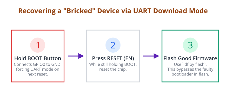
- Bricking the Device with a Faulty Bootloader:
- Mistake: Introducing an infinite loop (
while(1);) or a crash into the custom bootloader logic. - Symptom: The device resets continuously or produces no output after the first-stage ROM bootloader. The main application never runs.
- Fix: Recovery is almost always possible. Hold down the BOOT button, reset the device to enter UART Download Mode, and re-flash a known-good, complete firmware image (bootloader, partition table, and application) using
idf.py flash.
- Mistake: Introducing an infinite loop (
Exercises
- Boot Partition Selection: Extend the example. If GPIO0 is pressed during boot, make the bootloader attempt to load an application from a partition named
app_1instead of the default. If it’s not pressed, it should boot the default partition. This will require you to create a custom partition table with at least two app partitions. - Boot Counter in RTC Memory: Using the knowledge from Chapter 242, add a boot counter to your custom bootloader. Increment an
RTC_DATA_ATTRvariable and print its value every time the device boots, before the main application is loaded. - Visual Boot Indicator: In your custom bootloader, add code to blink an LED three times before proceeding to load the main application. This provides a clear visual confirmation that your custom bootloader is executing.
%%{ init: { 'theme': 'base', 'themeVariables': { 'fontFamily': 'Open Sans' } } }%%
flowchart TD
    A(Start Boot) --> B{Check GPIO0 State};
    B -- "Pressed (LOW)" --> C{"app_1" Partition Exists?};
    B -- "Not Pressed (HIGH)" --> F["Load Default Partition<br><i>(e.g., factory/ota_0)</i>"];

    C -- "Yes" --> D["Load <i>app_1</i> Partition<br><i class='code'>bootloader_load_partition(...)</i>"];
    C -- "No" --> E[Print Error<br>Load Default Partition];

    D --> G((Execute App 1));
    E --> F;
    F --> H((Execute Default App));

    classDef start fill:#EDE9FE,stroke:#5B21B6,stroke-width:2px,color:#5B21B6;
    classDef process fill:#DBEAFE,stroke:#2563EB,stroke-width:1px,color:#1E40AF;
    classDef decision fill:#FEF3C7,stroke:#D97706,stroke-width:1px,color:#92400E;
    classDef endo fill:#D1FAE5,stroke:#059669,stroke-width:2px,color:#065F46;
    classDef fail fill:#FEE2E2,stroke:#DC2626,stroke-width:1px,color:#991B1B;

    class A start;
    class B,C decision;
    class D,E,F process;
    class G,H endo;
    class E fail;
Summary
- ESP-IDF Uses a Two-Stage Boot Process: A non-modifiable ROM bootloader loads a modifiable second-stage bootloader from flash.
- Customization via Component Override: The safest way to create a custom bootloader is to copy the default
bootloadercomponent from ESP-IDF into your project’scomponentsdirectory. - The Bootloader is a Bare-Metal Environment: It runs before FreeRTOS and high-level drivers. You must use special bootloader utility functions or direct register access for I/O.
- Caution is Key: A faulty bootloader can prevent the device from booting. Always test thoroughly and know how to recover using UART Download Mode.
- Great Power, Great Responsibility: Custom bootloaders enable powerful features like conditional booting and pre-app hardware setup, forming the foundation for highly specialized and robust devices.
Further Reading
- ESP-IDF Programming Guide: Bootloader
- ESP-IDF Programming Guide: Secure Boot V2
- ESP32 Technical Reference Manual (Choose your specific variant)
- https://www.espressif.com/en/support/documentation/technical-docs (Essential for direct register access details).
