
Chapter 146: Capacitive Touch Sensors of ESP SoCs
Chapter Objectives
Upon completing this chapter, you will be able to:
- Understand the fundamental principles of capacitive touch sensing.
- Identify the ESP32 pins capable of touch functionality across different variants.
- Initialize and configure the touch pad peripheral using ESP-IDF.
- Read raw and filtered touch sensor values.
- Implement touch-based interrupts to trigger actions.
- Utilize filters to improve touch signal stability.
- Configure touch pads to wake the ESP32 from deep sleep mode.
- Recognize the differences in touch peripheral APIs for various ESP32 family members (ESP32/S2/S3 vs. C3/C6/H2).
- Troubleshoot common issues related to touch sensor implementation.
Introduction
Capacitive touch sensors have become ubiquitous in modern electronic devices, offering an intuitive and robust way for users to interact with interfaces. From smartphone screens to appliance control panels, touch sensing provides a sleek alternative to mechanical buttons and switches. The ESP32 family of microcontrollers integrates a built-in capacitive touch sensing peripheral, enabling developers to easily add touch-based controls to their embedded projects without requiring external touch controller ICs.
This chapter explores the theory behind capacitive touch sensing and provides a comprehensive guide to utilizing the touch sensor capabilities of ESP32 variants within the ESP-IDF v5.x framework. We will cover the setup, data acquisition, interrupt handling, and advanced features like filtering and wake-up from sleep, empowering you to build sophisticated and responsive user interfaces.
Theory
Principle of Capacitive Touch Sensing
Capacitive touch sensing works by measuring changes in capacitance. A capacitor is an electronic component that stores electrical energy in an electric field. It typically consists of two conductive plates separated by an insulating material called a dielectric. The capacitance (C) is a measure of a capacitor’s ability to store charge and is influenced by the surface area of the plates, the distance between them, and the properties of the dielectric material.
In a touch sensor application, one of these “plates” is a conductive pad (e.g., a copper area on a PCB) exposed to the user. The other “plate” can be considered the system ground or another nearby conductor. The human body is also conductive and has inherent capacitance. When a finger (or any conductive object) approaches or touches the sensor pad, it effectively changes the dielectric environment and adds its own capacitance to the system, coupling with the sensor pad. This results in a measurable increase in the total capacitance of the sensor pad.

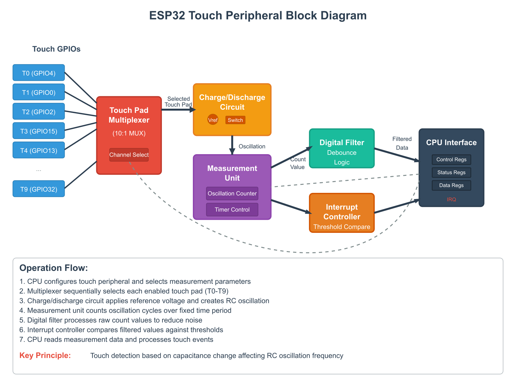
ESP32 Touch Peripheral Operation
The ESP32’s touch sensor peripheral operates based on the principle of charge-transfer or charge-discharge. Essentially, the peripheral measures the time it takes to charge or discharge the capacitance associated with a touch pad to a certain voltage level.
- Charging Phase: The touch sensor applies a voltage to the touch pad, charging its inherent capacitance.
- Discharging Phase: The pad is then discharged.
- Measurement: The ESP32 measures a value related to this charge/discharge cycle. This could be the time taken, or a count related to the number of charge/discharge cycles within a fixed period. When a finger touches the pad, the capacitance increases. A larger capacitance takes longer to charge/discharge, or will result in a different count value.
The raw value read from the sensor is typically inversely proportional to the capacitance: a higher capacitance (finger touch) results in a lower raw reading (as it might take fewer cycles of a fixed-duration charge pulse to reach a threshold, or a longer time which is then converted to a smaller numerical value by some internal logic). The exact relationship depends on the specific measurement method implemented in the hardware. It’s crucial to establish a baseline reading (no touch) and then detect deviations from this baseline when a touch occurs.
graph TD
    A[Start] --> B{Initialize Touch<br>Peripheral};
    B --> C["Configure Touch Pad<br>(GPIO, Voltage, etc.)"];
    C --> D{Measure Capacitance};
    D -- Charge/Discharge Cycle --> E[Get Raw Sensor Value];
    E --> F{Compare Value<br>with Threshold};
    F -- Value < Threshold<br>(Typical for ESP32) --> G((Touch Detected));
    F -- Value >= Threshold --> H((No Touch));
    G --> I[Output Event / Update Status];
    H --> I;
    I --> J[End / Wait for Next Cycle];

    classDef startNode fill:#EDE9FE,stroke:#5B21B6,stroke-width:2px,color:#5B21B6;
    classDef processNode fill:#DBEAFE,stroke:#2563EB,stroke-width:1px,color:#1E40AF;
    classDef decisionNode fill:#FEF3C7,stroke:#D97706,stroke-width:1px,color:#92400E;
    classDef endNode fill:#D1FAE5,stroke:#059669,stroke-width:2px,color:#065F46;
    classDef ioNode fill:#FEE2E2,stroke:#DC2626,stroke-width:1px,color:#991B1B;


    class A,J startNode;
    class B,C,D processNode;
    class E ioNode;
    class F decisionNode;
    class G,H,I endNode;
Key Concepts
| Concept | Description | Relevance to ESP32 |
|---|---|---|
| Touch Pads (Channels) | Specific conductive areas on a PCB connected to microcontroller pins that can detect changes in capacitance. | ESP32 variants have dedicated GPIO pins that can be configured as touch inputs (e.g., TOUCH_PAD_NUM0). |
| Threshold | A predefined sensor reading value used to distinguish between a touch and no-touch state. | Set using functions like touch_pad_set_thresh() or touch_sensor_set_thresholds(). Crossing this value triggers a touch event. |
| Baseline | The normal sensor reading when no touch is applied. This value can drift due to environmental factors. | Essential to measure at startup (calibration) to set an accurate threshold relative to the no-touch state. |
| Hysteresis | A small range or deadband around the threshold to prevent rapid, unwanted toggling of the touch state if the sensor reading fluctuates near the threshold. | Helps stabilize touch detection, preventing “bouncing” if a finger hovers or applies light pressure. Some ESP32 touch peripherals might have this built-in or it can be implemented in software. |
| Filters | Digital signal processing techniques (e.g., IIR filters) applied to raw sensor readings to reduce noise and improve signal stability. | ESP32 provides functions like touch_pad_filter_start() (ESP32/S2/S3) or touch_sensor_set_filter() (C3/C6/H2) to configure hardware-accelerated or software filters. |
| Interrupts | Hardware signals generated by the touch peripheral when a touch event (e.g., crossing a threshold) is detected, allowing the CPU to react without continuous polling. | Enables efficient, event-driven touch detection using touch_pad_isr_register() or touch_sensor_subscribe_event(). |
| Scan Mode | A feature where the touch peripheral automatically and sequentially measures readings from multiple configured touch pads. | The ESP32 touch controller handles scanning multiple pads. The driver allows configuration and reading from individual pads, which are scanned by the hardware. |
| Wake-up Source | The ability of touch pads to wake the ESP32 from low-power sleep modes when a touch is detected. | Crucial for battery-powered devices. Configured using esp_sleep_enable_touchpad_wakeup() or esp_sleep_enable_touch_wakeup(). |
Practical Examples
The following examples primarily use the driver/touch_pad.h API, which is common for ESP32, ESP32-S2, and ESP32-S3. Differences for ESP32-C3, ESP32-C6, and ESP32-H2, which use the driver/touch_sensor.h API, will be detailed in the “Variant Notes” section.
Prerequisites:
- ESP-IDF v5.x installed and configured with VS Code.
- An ESP32, ESP32-S2, or ESP32-S3 development board.
- A way to connect to a touch pad (e.g., a wire connected to the GPIO pin, or a dedicated touch pad on the PCB). For testing, simply touching the exposed part of a jumper wire connected to the correct GPIO pin is often sufficient.
Example 1: Basic Touch Pad Reading
This example initializes a single touch pad, reads its value periodically, and prints it to the serial monitor.
1. Identify a Touch Pad Pin:
Consult your ESP32 variant’s datasheet or the “Variant Notes” section below. For many ESP32 boards, TOUCH_PAD_NUM4 (GPIO4) is a common choice.
2. Code (main/touch_example_main.c):
#include <stdio.h>
#include "freertos/FreeRTOS.h"
#include "freertos/task.h"
#include "driver/touch_pad.h"
#include "esp_log.h"

static const char *TAG = "TouchExample";

// Define the touch pad to use (e.g., GPIO4 for ESP32)
#define TOUCH_PAD_PIN TOUCH_PAD_NUM4

void app_main(void)
{
    ESP_LOGI(TAG, "Initializing touch pad");

    // Initialize touch pad peripheral
    ESP_ERROR_CHECK(touch_pad_init());

    // Configure the touch pad interrupt threshold (not strictly needed for basic polling, but good practice)
    // This sets the threshold for triggering an interrupt if interrupts were enabled.
    // For polling, we compare the read value against our own logic.
    // For ESP32, a lower value means a stronger touch.
    // Let's find a baseline first.
    // ESP_ERROR_CHECK(touch_pad_set_thresh(TOUCH_PAD_PIN, TOUCH_THRESH_PERCENT * 0.8)); // Example: 80% of baseline

    // Set the touch sensor charge/discharge speed/cycles
    // These settings affect sensitivity and power consumption.
    // Refer to ESP-IDF documentation for details on these parameters.
    // For ESP32:
    ESP_ERROR_CHECK(touch_pad_set_voltage(TOUCH_HVOLT_2V7, TOUCH_LVOLT_0V5, TOUCH_HVOLT_ATTEN_1V));

    // Configure the specific touch pad
    ESP_ERROR_CHECK(touch_pad_config(TOUCH_PAD_PIN, 0)); // Second argument is threshold, 0 to disable ISR by threshold for now

    // For ESP32-S2 and ESP32-S3, you might need additional filter configuration
    // if you want to use touch_pad_read_filtered() effectively.
    // ESP_ERROR_CHECK(touch_pad_filter_start(10)); // Example filter period

    ESP_LOGI(TAG, "Touch pad initialized. Reading values from Pad %d:", TOUCH_PAD_PIN);

    uint16_t touch_value;
    uint16_t baseline = 0;

    // Simple calibration: Read a few values to establish a baseline
    for (int i = 0; i < 10; i++) {
        touch_pad_read_raw_data(TOUCH_PAD_PIN, &touch_value); // For ESP32
        // For ESP32-S2/S3, touch_pad_read_filtered(TOUCH_PAD_PIN, &touch_value); is often preferred after filter_start
        // Or use touch_pad_read(TOUCH_PAD_PIN, &touch_value); which is equivalent to raw on ESP32
        baseline += touch_value;
        vTaskDelay(pdMS_TO_TICKS(50));
    }
    baseline /= 10;
    ESP_LOGI(TAG, "Baseline (no touch) for Pad %d: %d", TOUCH_PAD_PIN, baseline);

    // Define a threshold relative to the baseline
    // A touch typically causes the value to decrease for these sensors.
    uint16_t touch_threshold = baseline * 0.8; // Example: 80% of baseline
    ESP_LOGI(TAG, "Touch threshold set to: %d", touch_threshold);


    while (1) {
        // For ESP32:
        esp_err_t err = touch_pad_read_raw_data(TOUCH_PAD_PIN, &touch_value);
        // For ESP32-S2/S3, you might prefer:
        // esp_err_t err = touch_pad_read_filtered(TOUCH_PAD_PIN, &touch_value);
        // Or the simpler:
        // esp_err_t err = touch_pad_read(TOUCH_PAD_PIN, &touch_value);

        if (err == ESP_OK) {
            ESP_LOGI(TAG, "Pad %d value: %5d | %s", TOUCH_PAD_PIN, touch_value, (touch_value < touch_threshold) ? "TOUCHED" : "Released");
        } else {
            ESP_LOGE(TAG, "Error reading touch pad: %s", esp_err_to_name(err));
        }
        vTaskDelay(pdMS_TO_TICKS(500)); // Read every 500ms
    }
}
3. CMakeLists.txt (in main directory):
Ensure your CMakeLists.txt includes the driver component.
idf_component_register(SRCS "touch_example_main.c"
                    INCLUDE_DIRS ".")
4. Build Instructions:
- Open VS Code.
- Ensure your ESP-IDF environment is sourced.
- Select your target ESP32 variant (e.g.,
esp32,esp32s2,esp32s3). - Build the project (Espressif IDF: Build Project).
5. Run/Flash/Observe Steps:
- Connect your ESP32 board to your computer.
- Flash the project (Espressif IDF: Flash Device).
- Open the ESP-IDF Monitor (Espressif IDF: Monitor Device).
- Observe the printed touch values. Touch the wire/pad connected to
TOUCH_PAD_PIN(e.g., GPIO4). You should see the values decrease significantly when touched.
Tip: The raw touch values are typically higher when not touched and lower when touched. The exact range depends on the hardware layout, finger pressure, and environmental conditions. A simple calibration at startup, as shown in the code, is recommended to establish a baseline.
Example 2: Touch Pad Interrupts
This example demonstrates how to use touch pad interrupts to detect a touch event without continuous polling.
graph TD
    subgraph Initialization
        A[Start] --> B{Initialize Touch Pad<br>Peripheral};
        B --> C["Configure Touch Pad<br>(e.g., GPIO4)"];
        C --> D[Calibrate Baseline];
        D --> E[Set Interrupt Threshold<br>Relative to Baseline];
        E --> F[Register ISR Handler];
        F --> G[Enable Touch Interrupt];
    end

    subgraph Runtime Task
        H[Touch Monitoring Task Starts] --> I{"Wait for Semaphore<br>(Task Blocks)"};
    end

    subgraph Interrupt Event
        J((User Touches Pad)) --> K{Hardware Detects<br>Value Crosses Threshold};
        K --> L[Touch Interrupt Triggered!];
        L --> M{ISR Handler Executed};
        M --> N[ISR Gives Semaphore];
    end

    Initialization --> H;
    N --> I;
    I -- Semaphore Taken --> O[Task Unblocks];
    O --> P{Read Touch Value};
    P --> Q[Log Event / Perform Action];
    Q --> I;

    classDef startNode fill:#EDE9FE,stroke:#5B21B6,stroke-width:2px,color:#5B21B6;
    classDef processNode fill:#DBEAFE,stroke:#2563EB,stroke-width:1px,color:#1E40AF;
    classDef decisionNode fill:#FEF3C7,stroke:#D97706,stroke-width:1px,color:#92400E;
    classDef eventNode fill:#FEE2E2,stroke:#DC2626,stroke-width:1px,color:#991B1B;
    classDef endNode fill:#D1FAE5,stroke:#059669,stroke-width:2px,color:#065F46;

    class A startNode;
    class B,C,D,E,F,G,H,P,Q processNode;
    class I decisionNode;
    class J,K,L,M,N eventNode;
    class O endNode;
1. Code (main/touch_interrupt_main.c):
#include <stdio.h>
#include "freertos/FreeRTOS.h"
#include "freertos/task.h"
#include "freertos/semphr.h" // For semaphores
#include "driver/touch_pad.h"
#include "esp_log.h"

static const char *TAG = "TouchInterrupt";
#define TOUCH_PAD_PIN TOUCH_PAD_NUM4 // Example: GPIO4

// Threshold for touch detection (percentage of baseline reading)
// A lower raw value means touch. So, threshold is set below baseline.
#define TOUCH_THRESH_PERCENT 80

static SemaphoreHandle_t s_touch_semaphore = NULL;
static uint16_t s_touch_baseline = 0;

// ISR handler for touch pad
static void touch_isr_handler(void *arg)
{
    uint32_t pad_intr = touch_pad_get_status();
    // Clear interrupt
    touch_pad_clear_status();

    if (pad_intr & (1 << TOUCH_PAD_PIN)) {
        // A touch event was detected on the configured pad
        xSemaphoreGiveFromISR(s_touch_semaphore, NULL);
    }
}

void touch_monitoring_task(void *pvParameter)
{
    uint16_t touch_value;
    ESP_LOGI(TAG, "Touch monitoring task started. Waiting for touch events on Pad %d.", TOUCH_PAD_PIN);

    while (1) {
        // Wait for the semaphore to be given by the ISR
        if (xSemaphoreTake(s_touch_semaphore, portMAX_DELAY) == pdTRUE) {
            // For ESP32, touch_pad_read() or touch_pad_read_raw_data()
            // For ESP32-S2/S3, touch_pad_read_filtered() is often better
            esp_err_t err = touch_pad_read_raw_data(TOUCH_PAD_PIN, &touch_value);
            if (err == ESP_OK) {
                 ESP_LOGI(TAG, "Pad %d touched! Value: %d (Baseline: %d, Threshold: %d)",
                    TOUCH_PAD_PIN, touch_value, s_touch_baseline, (s_touch_baseline * TOUCH_THRESH_PERCENT) / 100);
            } else {
                ESP_LOGE(TAG, "Error reading touch pad after interrupt: %s", esp_err_to_name(err));
            }
            // Optional: Add a small delay to debounce or prevent rapid re-triggering if needed
            vTaskDelay(pdMS_TO_TICKS(200));
            // Re-enable interrupt (if it was one-shot, or to be sure)
            // touch_pad_intr_enable(); // Usually not needed as it's level-triggered by default
        }
    }
}

void app_main(void)
{
    ESP_LOGI(TAG, "Initializing touch pad with interrupt");

    s_touch_semaphore = xSemaphoreCreateBinary();
    if (s_touch_semaphore == NULL) {
        ESP_LOGE(TAG, "Failed to create semaphore");
        return;
    }

    ESP_ERROR_CHECK(touch_pad_init());
    ESP_ERROR_CHECK(touch_pad_set_voltage(TOUCH_HVOLT_2V7, TOUCH_LVOLT_0V5, TOUCH_HVOLT_ATTEN_1V));
    ESP_ERROR_CHECK(touch_pad_config(TOUCH_PAD_PIN, 0)); // Configure pad, threshold 0 initially

    // Calibrate to find baseline
    uint16_t temp_val;
    for (int i = 0; i < 10; i++) {
        touch_pad_read_raw_data(TOUCH_PAD_PIN, &temp_val);
        s_touch_baseline += temp_val;
        vTaskDelay(pdMS_TO_TICKS(20));
    }
    s_touch_baseline /= 10;
    uint16_t threshold = (s_touch_baseline * TOUCH_THRESH_PERCENT) / 100;
    ESP_LOGI(TAG, "Baseline for Pad %d: %d, Interrupt Threshold set to: %d", TOUCH_PAD_PIN, s_touch_baseline, threshold);

    // Set the threshold for the interrupt
    ESP_ERROR_CHECK(touch_pad_set_thresh(TOUCH_PAD_PIN, threshold));

    // Register the ISR
    ESP_ERROR_CHECK(touch_pad_isr_register(touch_isr_handler, NULL, TOUCH_PAD_INTR_MASK_ACTIVE));
    // Enable the interrupt for the touch pad
    ESP_ERROR_CHECK(touch_pad_intr_enable(TOUCH_PAD_INTR_MASK_ACTIVE)); // Or TOUCH_PAD_INTR_MASK_ALL

    xTaskCreate(&touch_monitoring_task, "touch_task", 2048, NULL, 5, NULL);

    ESP_LOGI(TAG, "Setup complete. Touch Pad %d to trigger interrupt.", TOUCH_PAD_PIN);
}
2. Build, Flash, and Observe:
Follow the same build and flash steps as Example 1. Open the monitor. The system will now log a message only when the touch pad is pressed beyond the calibrated threshold.
What is a Semaphore? In FreeRTOS (and other operating systems), a semaphore is a signaling mechanism. In this example,
s_touch_semaphoreis a binary semaphore. The Interrupt Service Routine (ISR)touch_isr_handler“gives” or “signals” the semaphore when a touch is detected. Thetouch_monitoring_task“takes” or “waits” for this semaphore. This is an efficient way to have a task react to an event triggered by an interrupt without busy-waiting. Refer to Chapter 13 for more details on semaphores.
Example 3: Using Filters (ESP32-S2/S3 and compatible with ESP32)
Filters help to smooth out the touch readings, making them less susceptible to noise. The touch_pad API provides an IIR (Infinite Impulse Response) filter.
1. Code (main/touch_filter_main.c):
#include <stdio.h>
#include "freertos/FreeRTOS.h"
#include "freertos/task.h"
#include "driver/touch_pad.h"
#include "esp_log.h"

static const char *TAG = "TouchFilter";
#define TOUCH_PAD_PIN TOUCH_PAD_NUM4 // Example: GPIO4
#define FILTER_PERIOD_MS 10 // Filter sample period in ms

void app_main(void)
{
    ESP_LOGI(TAG, "Initializing touch pad with filter");

    ESP_ERROR_CHECK(touch_pad_init());
    ESP_ERROR_CHECK(touch_pad_set_voltage(TOUCH_HVOLT_2V7, TOUCH_LVOLT_0V5, TOUCH_HVOLT_ATTEN_1V));
    ESP_ERROR_CHECK(touch_pad_config(TOUCH_PAD_PIN, 0));

    // Initialize and start the filter
    // This is more relevant for ESP32-S2/S3, but can be used on ESP32.
    // On ESP32, touch_pad_read_filtered might give similar results to touch_pad_read_raw_data
    // if filter is not explicitly configured or if its effect is minimal for the basic ESP32 touch controller.
    ESP_LOGI(TAG, "Starting IIR filter with period %dms", FILTER_PERIOD_MS);
    ESP_ERROR_CHECK(touch_pad_filter_set_config(TOUCH_FILTER_IIR_16)); // Set filter mode (e.g., IIR 16 samples)
    ESP_ERROR_CHECK(touch_pad_filter_start(FILTER_PERIOD_MS));


    uint16_t raw_value, filtered_value;
    uint16_t baseline_filtered = 0;

    // Simple calibration for filtered values
    for (int i = 0; i < 20; i++) { // Longer calibration for filtered values to settle
        touch_pad_read_filtered(TOUCH_PAD_PIN, &filtered_value);
        baseline_filtered += filtered_value;
        vTaskDelay(pdMS_TO_TICKS(50));
    }
    baseline_filtered /= 20;
    ESP_LOGI(TAG, "Filtered baseline (no touch) for Pad %d: %d", TOUCH_PAD_PIN, baseline_filtered);
    uint16_t touch_threshold_filtered = baseline_filtered * 0.8; // 80% of filtered baseline
    ESP_LOGI(TAG, "Filtered touch threshold set to: %d", touch_threshold_filtered);


    ESP_LOGI(TAG, "Reading raw and filtered values from Pad %d:", TOUCH_PAD_PIN);

    while (1) {
        esp_err_t err_raw = touch_pad_read_raw_data(TOUCH_PAD_PIN, &raw_value);
        esp_err_t err_filtered = touch_pad_read_filtered(TOUCH_PAD_PIN, &filtered_value);

        if (err_raw == ESP_OK && err_filtered == ESP_OK) {
            ESP_LOGI(TAG, "Pad %d Raw: %5d, Filtered: %5d | %s",
                     TOUCH_PAD_PIN, raw_value, filtered_value,
                     (filtered_value < touch_threshold_filtered) ? "TOUCHED" : "Released");
        } else {
            ESP_LOGE(TAG, "Error reading touch pad. Raw: %s, Filtered: %s",
                     esp_err_to_name(err_raw), esp_err_to_name(err_filtered));
        }
        vTaskDelay(pdMS_TO_TICKS(200));
    }
}
2. Build, Flash, and Observe:
Compile, flash, and monitor. Compare the stability of the filtered_value against the raw_value, especially if you introduce some electrical noise near the touch wire (e.g., by bringing a switched-mode power supply nearby, carefully).
Example 4: Touch Pad Wake-up from Deep Sleep
Touch pads can be used as a wake-up source from deep sleep, which is excellent for low-power applications.
graph TD
    A[Start / Boot] --> B{Initialize Touch Pad};
    B --> C["Configure Touch Pad<br>for Wake-up (e.g., GPIO4)"];
    C --> D[Calibrate Baseline];
    D --> E[Set Wake-up Threshold];
    E --> F["Set Trigger Mode<br>(e.g., TOUCH_TRIGGER_BELOW)"];
    F --> G["Enable Touchpad Wake-up Source<br>esp_sleep_enable_touchpad_wakeup()"];
    G --> H((ESP32 Enters Deep Sleep));

    H -. Wait for Touch .-> I((User Touches Configured Pad));
    I --> J["Capacitance Change<br>Crosses Threshold"];
    J --> K[Hardware Wake-up Signal Generated];
    K --> L((ESP32 Wakes Up));

    L --> M["Read Wake-up Cause<br>esp_sleep_get_wakeup_cause()"];
    M -- ESP_SLEEP_WAKEUP_TOUCHPAD --> N["Identify Touched Pad<br>esp_sleep_get_touchpad_wakeup_status()"];
    N --> O["Process Touch Event<br>(e.g., Log, Increment Counter)"];
    M -- Other Reason --> P[Handle Other Wake-up Reason];
    O --> Q["Re-configure for Sleep /<br>Continue Application Logic"];
    P --> Q;
    Q --> H;

    classDef startNode fill:#EDE9FE,stroke:#5B21B6,stroke-width:2px,color:#5B21B6;
    classDef processNode fill:#DBEAFE,stroke:#2563EB,stroke-width:1px,color:#1E40AF;
    classDef decisionNode fill:#FEF3C7,stroke:#D97706,stroke-width:1px,color:#92400E;
    classDef sleepNode fill:#A78BFA,stroke:#5B21B6,stroke-width:2px,color:#FFFFFF;
    classDef eventNode fill:#FCD34D,stroke:#D97706,stroke-width:1px,color:#92400E;
    classDef wakeupNode fill:#6EE7B7,stroke:#059669,stroke-width:2px,color:#065F46;

    class A,Q startNode;
    class B,C,D,E,F,G,N,O,P processNode;
    class H sleepNode;
    class I,J,K eventNode;
    class L wakeupNode;
    class M decisionNode;
1. Code (main/touch_wakeup_main.c):
#include <stdio.h>
#include "freertos/FreeRTOS.h"
#include "freertos/task.h"
#include "driver/touch_pad.h"
#include "esp_sleep.h"
#include "esp_log.h"

static const char *TAG = "TouchWakeup";
#define TOUCH_PAD_PIN_WAKEUP TOUCH_PAD_NUM4 // GPIO4 for ESP32

// Store the wake-up reason
RTC_DATA_ATTR static int boot_count = 0;
RTC_DATA_ATTR static esp_sleep_wakeup_cause_t wakeup_reason;

void app_main(void)
{
    boot_count++;
    ESP_LOGI(TAG, "Boot count: %d", boot_count);

    // Get wakeup reason
    wakeup_reason = esp_sleep_get_wakeup_cause();

    if (boot_count == 1) { // First boot
        ESP_LOGI(TAG, "First boot. Configuring touch pad for wakeup.");
    } else { // Woke up from sleep
        if (wakeup_reason == ESP_SLEEP_WAKEUP_TOUCHPAD) {
            uint32_t touch_pad_num = esp_sleep_get_touchpad_wakeup_status();
            uint16_t value;
            // Note: After wakeup, touch_pad_read might not give the value that triggered the wakeup immediately.
            // The status function gives the pad number.
            touch_pad_read(touch_pad_num, &value); // Read the value of the pad that caused wakeup
            ESP_LOGI(TAG, "Woke up by touch on Pad %lu! Current value: %u", touch_pad_num, value);
        } else {
            ESP_LOGI(TAG, "Woke up by other reason: %d", wakeup_reason);
        }
    }

    // Initialize touch pad peripheral
    ESP_ERROR_CHECK(touch_pad_init());
    ESP_ERROR_CHECK(touch_pad_set_voltage(TOUCH_HVOLT_2V7, TOUCH_LVOLT_0V5, TOUCH_HVOLT_ATTEN_1V));

    // Configure the touch pad for wakeup
    ESP_ERROR_CHECK(touch_pad_config(TOUCH_PAD_PIN_WAKEUP, 0)); // Threshold 0 for now

    // Calibrate and set threshold for wakeup
    uint16_t baseline = 0;
    uint16_t touch_value;
    for(int i=0; i<5; ++i) {
        touch_pad_read(TOUCH_PAD_PIN_WAKEUP, &touch_value);
        baseline += touch_value;
        vTaskDelay(pdMS_TO_TICKS(20));
    }
    baseline /= 5;
    uint16_t wakeup_threshold = baseline * 0.8; // 80% of baseline
    ESP_LOGI(TAG, "Pad %d baseline: %u, wakeup threshold: %u", TOUCH_PAD_PIN_WAKEUP, baseline, wakeup_threshold);
    ESP_ERROR_CHECK(touch_pad_set_thresh(TOUCH_PAD_PIN_WAKEUP, wakeup_threshold));

    // ESP32 specific: Set trigger mode for wakeup
    ESP_ERROR_CHECK(touch_pad_set_trigger_mode(TOUCH_TRIGGER_BELOW)); // Trigger if value is below threshold

    // Enable touchpad wakeup
    ESP_ERROR_CHECK(esp_sleep_enable_touchpad_wakeup());
    // Optional: Configure sleep options (e.g., disable WiFi, BT before sleep)
    // esp_sleep_pd_config(ESP_PD_DOMAIN_RTC_PERIPH, ESP_PD_OPTION_ON); // Keep RTC peripherals on

    ESP_LOGI(TAG, "Entering deep sleep. Touch Pad %d to wake up.", TOUCH_PAD_PIN_WAKEUP);

    // Add a small delay to allow log messages to be sent
    vTaskDelay(pdMS_TO_TICKS(100));

    esp_deep_sleep_start(); // Enter deep sleep
}
2. Build, Flash, and Observe:
Flash the code. The ESP32 will print calibration info, then enter deep sleep. Touch the designated pad. The ESP32 will wake up, print a message indicating it was woken by touch, and then go back to sleep.
Warning:
RTC_DATA_ATTRis used to storeboot_countandwakeup_reasonin RTC memory, so their values persist across deep sleep cycles. When waking from deep sleep, the system essentially reboots, but these variables retain their state.
Variant Notes
The ESP32 family has several variants, and their touch peripheral capabilities and APIs can differ.
| Variant | Touch API Header | No. of Touch Pins | Pin Designations (Enum touch_pad_t to GPIO) |
Key Features/Notes |
|---|---|---|---|---|
| ESP32 | driver/touch_pad.h |
10 |
TOUCH_PAD_NUM0 (GPIO4)TOUCH_PAD_NUM1 (GPIO0)TOUCH_PAD_NUM2 (GPIO2)TOUCH_PAD_NUM3 (GPIO15)TOUCH_PAD_NUM4 (GPIO13)TOUCH_PAD_NUM5 (GPIO12)TOUCH_PAD_NUM6 (GPIO14)TOUCH_PAD_NUM7 (GPIO27)TOUCH_PAD_NUM8 (GPIO33)TOUCH_PAD_NUM9 (GPIO32)
|
Original touch controller. Some pins shared with JTAG or strapping functions (e.g., GPIO0, GPIO15, GPIO12-14). Always check board schematic for conflicts. |
| ESP32-S2 | driver/touch_pad.h |
14 |
TOUCH_PAD_NUM1 (GPIO1) toTOUCH_PAD_NUM14 (GPIO14)
|
Improved touch sensing module compared to ESP32. More sensitive and robust. Supports hardware-accelerated filters. touch_pad_read_filtered() is recommended. |
| ESP32-S3 | driver/touch_pad.h |
14 |
TOUCH_PAD_NUM1 (GPIO1) toTOUCH_PAD_NUM14 (GPIO14)
|
Similar touch capabilities to ESP32-S2. Robust controller with hardware filter support. |
| Variant | Touch API Header | No. of Touch Pins | Pin Designations (touch_sensor_channel_t to GPIO) |
Key Features/Notes |
|---|---|---|---|---|
| ESP32-C3 | driver/touch_sensor.h |
5 |
TOUCH_SENSOR_CHANNEL_0 (GPIO0)TOUCH_SENSOR_CHANNEL_1 (GPIO1)TOUCH_SENSOR_CHANNEL_2 (GPIO2)TOUCH_SENSOR_CHANNEL_3 (GPIO3)TOUCH_SENSOR_CHANNEL_4 (GPIO4)
|
Uses newer touch_sensor.h API. RISC-V core. Pins often shared (strapping, UART). Check board schematic carefully. More configurable touch controller. |
| ESP32-C6 | driver/touch_sensor.h |
7 |
TOUCH_SENSOR_CHANNEL_0 (GPIO0) toTOUCH_SENSOR_CHANNEL_6 (GPIO6)
|
Uses newer touch_sensor.h API. RISC-V core. Advanced touch controller similar to C3. Check pin functions on specific boards. |
| ESP32-H2 | driver/touch_sensor.h |
7 |
TOUCH_SENSOR_CHANNEL_0 (GPIO0) toTOUCH_SENSOR_CHANNEL_6 (GPIO6)
|
Uses newer touch_sensor.h API. RISC-V core. Features an IEEE 802.15.4 radio. Touch controller similar to C3/C6. Verify pin availability. |
Example Snippet for ESP32-C3/C6/H2 (Basic Read):
#include "driver/touch_sensor.h"
#include "esp_log.h"
#include "freertos/FreeRTOS.h"
#include "freertos/task.h"

static const char *TAG_C3 = "TouchSensor_C3";
#define C3_TOUCH_CHANNEL TOUCH_SENSOR_CHANNEL_0 // Corresponds to GPIO0 on ESP32-C3

void app_main_c3_example(void) {
    touch_sensor_config_t touch_cfg = {
        .channel_num = C3_TOUCH_CHANNEL,
        // Set other parameters like grade, cap_level, slope, etc.
        // These are specific to the new controller and affect sensitivity.
        // Refer to touch_sensor_config_t documentation.
        // Example (default-like values might need tuning):
        .grade = TOUCH_SENSOR_GRADE_8, // Sensitivity grade
        .cap_level = TOUCH_SENSOR_CAP_LEVEL_6, // Capacitance level
        .slope = TOUCH_SENSOR_SLOPE_7, // Charge/discharge slope
        .meas_mode = TOUCH_MEAS_MODE_TIMER, // Measurement mode
    };

    ESP_LOGI(TAG_C3, "Initializing touch sensor for ESP32-C3/C6/H2 style");
    ESP_ERROR_CHECK(touch_sensor_install()); // Install the driver
    ESP_ERROR_CHECK(touch_sensor_config(&touch_cfg)); // Configure the channel
    ESP_ERROR_CHECK(touch_sensor_start()); // Start measurement

    uint32_t raw_value;
    uint32_t smooth_value;
    uint32_t baseline = 0;

    // Simple calibration
    for (int i = 0; i < 10; i++) {
        touch_sensor_read_raw_data(C3_TOUCH_CHANNEL, &raw_value);
        baseline += raw_value;
        vTaskDelay(pdMS_TO_TICKS(50));
    }
    baseline /= 10;
    ESP_LOGI(TAG_C3, "Baseline for Channel %d: %lu", C3_TOUCH_CHANNEL, baseline);
    uint32_t threshold = baseline * 0.8; // Example threshold

    while(1) {
        touch_sensor_read_raw_data(C3_TOUCH_CHANNEL, &raw_value);
        touch_sensor_read_smooth_data(C3_TOUCH_CHANNEL, &smooth_value); // If filter enabled via set_filter
        ESP_LOGI(TAG_C3, "Channel %d Raw: %5lu, Smooth: %5lu | %s",
                 C3_TOUCH_CHANNEL, raw_value, smooth_value,
                 (raw_value < threshold) ? "TOUCHED" : "Released");
        vTaskDelay(pdMS_TO_TICKS(500));
    }
    // touch_sensor_stop();
    // touch_sensor_uninstall();
}
| Feature / Operation | driver/touch_pad.h(ESP32, ESP32-S2, ESP32-S3) |
driver/touch_sensor.h(ESP32-C3, C6, H2) |
|---|---|---|
| Driver Installation/ Uninstallation |
touch_pad_init()touch_pad_deinit() (Global) |
touch_sensor_install()touch_sensor_uninstall() (Global) |
| Pad/Channel Configuration | touch_pad_config() (Per pad) |
touch_sensor_config() (Per channel, uses touch_sensor_config_t struct) |
| Measurement Start/Stop | Implicitly started after touch_pad_init() and touch_pad_config(). |
touch_sensor_start()touch_sensor_stop() |
| Reading Values | touch_pad_read_raw_data()touch_pad_read_filtered()touch_pad_read() |
touch_sensor_read_raw_data()touch_sensor_read_smooth_data()touch_sensor_read_benchmark_data() |
| Setting Thresholds | touch_pad_set_thresh() (Per pad) |
touch_sensor_set_thresholds() (Per channel, for active/inactive) |
| Filter Configuration | touch_pad_filter_set_config()touch_pad_filter_start()touch_pad_filter_stop() |
touch_sensor_set_filter_config()touch_sensor_filter_enable()touch_sensor_filter_disable() (Uses touch_filter_config_t) |
| Interrupt Handling | touch_pad_isr_register()touch_pad_intr_enable()touch_pad_intr_disable() |
touch_sensor_subscribe_event()touch_sensor_unsubscribe_event() (Event-based, more flexible using touch_event_config_t) |
| Sleep Wake-up Enable | esp_sleep_enable_touchpad_wakeup() |
esp_sleep_enable_touch_wakeup() (Note: “touch” vs “touchpad”) |
| Voltage Configuration | touch_pad_set_voltage() |
Part of touch_sensor_config_t (e.g., slope, ref_voltage, cap_level) |
Tip: When working with ESP32-C3, C6, or H2, always refer to the
driver/touch_sensor.hheader and the ESP-IDF API documentation for the most accurate and detailed configuration options, as their touch controller is more advanced and has more parameters to tune.
Common Mistakes & Troubleshooting Tips
| Mistake / Issue | Symptom(s) | Troubleshooting / Solution |
|---|---|---|
| Incorrect Pin Configuration | Touch not detected at all; erratic behavior on unrelated peripherals; system instability. |
Solution: 1. Verify Datasheet: Always consult the datasheet for your specific ESP32 variant (ESP32, S2, S3, C3, C6, H2) to identify valid touch pins. 2. Check Pin Mapping: Ensure the touch_pad_t enum (for ESP32/S2/S3) or touch_sensor_channel_t (for C3/C6/H2) corresponds to the correct physical GPIO pin you are using.3. Avoid Conflicts: Confirm the chosen pin is not multiplexed for other critical functions (e.g., JTAG TDO/TMS/TDI/TCK, strapping pins like GPIO0, SPI flash pins) unless you have explicitly handled the configuration. Check your development board’s schematic. |
| Thresholds Set Incorrectly | No touch detected (threshold too low/high); false touches registered (threshold too sensitive); inconsistent detection. |
Solution: 1. Calibrate Baseline: Implement a calibration routine at startup to read the “no-touch” sensor value. This is your baseline. 2. Relative Threshold: Set the touch threshold relative to this baseline. For ESP32 (where touch values decrease), a common starting point is 70-80% of the baseline (e.g., threshold = baseline * 0.8). For systems where values increase, it would be higher than baseline.3. Log Values: Print raw sensor values to the serial monitor to observe the range with and without touch to fine-tune the threshold. 4. Dynamic Adjustment: For long-running applications or varying environments, consider implementing dynamic baseline tracking or periodic re-calibration. |
| Noise Interference | Erratic or unstable touch readings; false positives; fluctuating baseline values. |
Solution: 1. Short Wires: Keep wires from the ESP32 pin to the touch electrode (pad) as short as possible. 2. Shielding: If long wires are unavoidable, consider using shielded cables with the shield connected to ground. 3. Grounding: Ensure proper grounding of your PCB and the overall system. A dedicated ground plane near touch pads can help. 4. Filters: Utilize built-in hardware/software filters: – ESP32/S2/S3: touch_pad_filter_start(), touch_pad_filter_set_config().
– C3/C6/H2: touch_sensor_set_filter_config(), touch_sensor_filter_enable().5. Bypass Capacitors: Add bypass capacitors (e.g., 0.1uF, 10uF) close to the ESP32’s VDD and GND pins. 6. Software Debouncing: Implement software debouncing logic (e.g., require multiple consecutive readings beyond threshold before confirming a touch). 7. Physical Separation: Keep touch traces away from noisy digital lines or power supply components on the PCB. |
| Forgetting Initialization or Enable Steps | Crashes, ESP_FAIL errors, or no readings when trying to access touch functions. Interrupts not firing. |
Solution: Follow the correct API sequence: 1. Global Init: Call touch_pad_init() (ESP32/S2/S3) or touch_sensor_install() (C3/C6/H2) once.2. Pad/Channel Config: Configure each specific pad/channel using touch_pad_config() or touch_sensor_config().3. Start (C3/C6/H2): For C3/C6/H2, call touch_sensor_start() after installation and configuration.4. Filters/Thresholds: Set up filters and thresholds after initialization and pad/channel configuration. 5. Interrupts: If using interrupts: – ESP32/S2/S3: Register ISR with touch_pad_isr_register() THEN enable with touch_pad_intr_enable().
– C3/C6/H2: Subscribe to events using touch_sensor_subscribe_event().
|
| Misunderstanding API Differences Between Variants | Compilation errors (unknown functions/types); runtime errors; unexpected behavior when porting code between ESP32 families. |
Solution: 1. Identify Target: Always confirm your target ESP32 variant. 2. Use Correct Header: – For ESP32, ESP32-S2, ESP32-S3: Use driver/touch_pad.h.
– For ESP32-C3, ESP32-C6, ESP32-H2: Use driver/touch_sensor.h.3. Consult API Docs: Refer to the ESP-IDF documentation specific to your variant and API version (e.g., v5.x). Pay close attention to function names, parameter types (especially config structs), and typical call sequences. See the API Comparison Table. |
| Incorrect Voltage Settings / Sensitivity Tuning | Poor sensitivity (hard to trigger touch); overly sensitive (false triggers); inconsistent readings across pads. |
Solution: 1. ESP32/S2/S3: Experiment with touch_pad_set_voltage(hvolt, lvolt, atten). Common values are TOUCH_HVOLT_2V7, TOUCH_LVOLT_0V5, TOUCH_HVOLT_ATTEN_1V. Incorrect attenuation can significantly affect range.2. C3/C6/H2: Sensitivity is tuned via parameters in touch_sensor_config_t like grade, cap_level, slope, and ref_voltage. Refer to documentation for details on how these affect the measurement range and sensitivity.3. Iterate & Test: Adjust settings, re-calibrate baseline, and test. Observe raw values to understand the impact of changes. |
Exercises
- Multi-Pad LED Control:
- Connect three LEDs to different GPIOs.
- Configure three distinct touch pads.
- Write a program where touching Pad 1 lights up LED 1, Pad 2 lights up LED 2, and Pad 3 lights up LED 3. Only one LED should be on at a time.
- Ensure you use appropriate thresholds for each pad.
- Touch Slider for LED Brightness:
- Use 3 or 4 touch pads arranged linearly to simulate a slider.
- Connect an LED to a GPIO pin capable of PWM (use the LEDC peripheral, see Chapter 145).
- Implement logic to determine the “position” on the slider based on which touch pad (or combination) is active.
- Control the LED brightness using PWM based on the slider position (e.g., Pad 1 = 25% brightness, Pad 2 = 50%, Pad 3 = 75%, Pad 4 = 100%).
- Deep Sleep Wake-up Counter:
- Modify Example 4 (Touch Pad Wake-up).
- Instead of just printing a wake-up message, increment a counter stored in RTC memory each time the device wakes up due to a touch event.
- Print the current wake-up count after each touch-induced wake-up.
- Add a second touch pad that, when pressed, resets this counter in RTC memory.
- All Pads Scanner and Visualizer:
- Identify all available touch pads on your specific ESP32 board.
- Write a program that periodically reads the values from all configured touch pads.
- Print the values in a formatted way (e.g., “Pad 0: XXXX, Pad 1: YYYY, …”).
- Indicate which pad is currently being touched by comparing its value against a dynamically calibrated threshold for that pad.
- Filter Experimentation (for ESP32-S2/S3 or C3/C6/H2):
- Set up a single touch pad and read its raw and filtered values (use
touch_pad_read_filteredfor S2/S3 ortouch_sensor_read_smooth_dataaftertouch_sensor_set_filterfor C3/C6/H2). - Experiment with different filter settings (e.g.,
TOUCH_FILTER_IIR_4/8/16for S2/S3, or differenttouch_filter_config_tfor C3/C6/H2). - Observe the output with and without introducing electrical noise (e.g., by bringing a phone or a noisy power adapter close to the touch wire). Document how different filter settings affect stability and responsiveness.
- Set up a single touch pad and read its raw and filtered values (use
Summary
- Capacitive touch sensing detects changes in capacitance caused by a user’s touch.
- ESP32 microcontrollers integrate touch sensor peripherals, allowing GPIOs to be used as touch pads.
- The
touch_pad.hAPI is used for ESP32, ESP32-S2, and ESP32-S3, involvingtouch_pad_init(),touch_pad_config(), andtouch_pad_read_raw_data()/touch_pad_read_filtered(). - The
touch_sensor.hAPI is used for ESP32-C3, ESP32-C6, and ESP32-H2, with functions liketouch_sensor_install(),touch_sensor_config(), andtouch_sensor_read_raw_data()/touch_sensor_read_smooth_data(). - Calibration is crucial to establish a baseline reading for reliable touch detection. Thresholds should be set relative to this baseline.
- Interrupts allow the system to react to touch events efficiently without constant polling.
- Filters (e.g., IIR) can improve the stability of touch readings by reducing noise.
- Touch pads can be configured as a wake-up source from deep sleep, enabling low-power applications.
- Always check the specific ESP32 variant and its datasheet for available touch pins and potential conflicts.
Further Reading
- ESP-IDF Programming Guide – Touch Sensor (ESP32, ESP32-S2, ESP32-S3):
- https://docs.espressif.com/projects/esp-idf/en/v5.4/esp32/api-reference/peripherals/touch_pad.html
- (For S2/S3, navigate to their respective sections in the documentation, but the API driver is largely the same
touch_pad.h)
- ESP-IDF Programming Guide – Touch Sensor (ESP32-C3):
- ESP-IDF Programming Guide – Touch Sensor (ESP32-C6):
- ESP-IDF Programming Guide – Touch Sensor (ESP32-H2):
- ESP-IDF Peripheral Examples on GitHub:
- https://github.com/espressif/esp-idf/tree/v5.4/examples/peripherals/touch_pad (Check subdirectories for different variants or touch controller versions)
- Application Notes: Search the Espressif website for application notes related to “capacitive touch design” or “touch sensor” for more in-depth hardware design considerations.
