
Chapter 170: Camera Interface with ParIO
Chapter Objectives
After completing this chapter, you will be able to:
- Understand the architecture of parallel camera modules and the Digital Video Port (DVP) interface.
- Identify the key signals involved in parallel camera communication (PCLK, HSYNC, VSYNC, Data).
- Learn about common camera pixel formats (e.g., YUV422, RGB565, JPEG).
- Understand how camera sensors are configured (typically via SCCB/I2C).
- Configure and use the ESP-IDF
esp_cameradriver to interface with a parallel camera. - Capture image frames from a camera and access the frame buffer data.
- Recognize the role of DMA in efficient camera frame capture.
- Identify common issues and troubleshoot parallel camera interfacing problems.
Introduction
In our exploration of ESP32 peripherals, the ability to capture and process images opens up a vast range of applications, from simple object detection and QR code scanning to more complex video streaming and machine vision tasks. Many camera modules, especially those offering a good balance of resolution and cost, utilize a parallel interface for high-speed data transfer.
This chapter focuses on interfacing such parallel cameras with ESP32 microcontrollers. We will primarily discuss the Digital Video Port (DVP) interface, a common standard for parallel camera modules. You will learn how to configure the necessary hardware connections and use the esp_camera component provided by ESP-IDF to initialize the camera, capture frames, and access image data. This builds upon your understanding of Parallel I/O (ParIO) by applying it to the specific context of high-speed image data acquisition.
Theory
Parallel Camera Interface: Digital Video Port (DVP)
The Digital Video Port (DVP) is a common parallel interface standard for connecting image sensors to processors. It allows for the direct, high-speed transfer of raw pixel data.
Key Signals in a DVP Interface:
- Pixel Clock (
PCLKorXCLKfor sensor input clock,PIXCLKfor pixel output clock):XCLK/MCLK (System Master Clock Input): An input clock provided by the MCU to the camera sensor to drive its internal operations. The frequency of XCLK is critical and specified in the camera sensor’s datasheet.PCLK (Pixel Clock Output): An output clock generated by the camera sensor. Each pulse of PCLK typically signifies that valid pixel data is available on the data lines. The ESP32 latches the data bits on a specific edge (rising or falling) of PCLK.
- Horizontal Synchronization (
HSYNCorHREF): An output signal from the camera sensor that indicates the active period of a single line of pixels. When HSYNC is active, the data on the D[0:7] lines represents valid pixels for the current row. - Vertical Synchronization (
VSYNC): An output signal from the camera sensor that indicates the active period of an entire frame. It signals the start and end of a complete image frame. - Data Lines (
D[0:7]orD[0:9]etc.): These are parallel unidirectional lines carrying the pixel data from the camera sensor to the MCU. Common configurations are 8-bit, but 10-bit or 12-bit interfaces also exist for higher bit-depth sensors. For an 8-bit interface, one byte of pixel data is transferred per PCLK cycle. - Shutdown (
PWDNorRESET): Control lines to power down or reset the camera sensor.
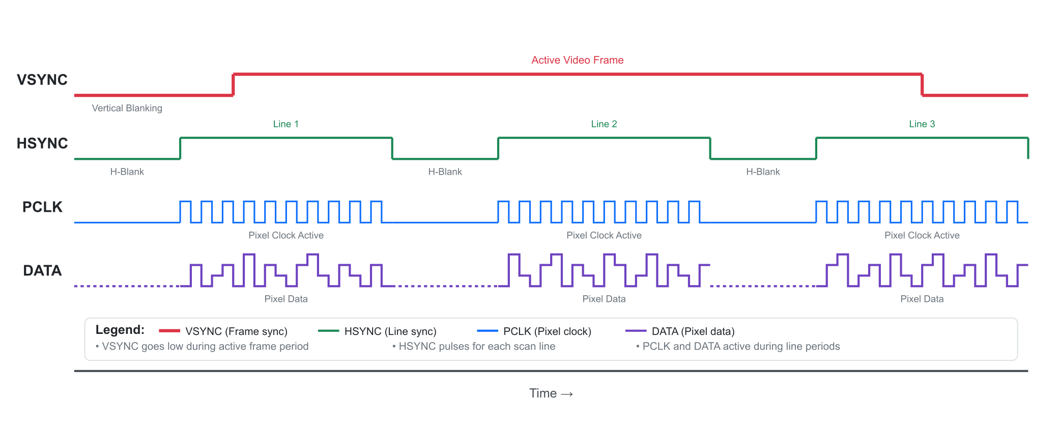
Frame Structure:
A complete image frame is defined by the VSYNC signal. Within one VSYNC period (from one active edge to the next corresponding active edge), there are multiple HSYNC pulses. Each HSYNC pulse corresponds to one horizontal line of pixels. During the active period of HSYNC, pixel data is clocked out on the data lines, synchronized by PCLK. The periods outside active HSYNC/VSYNC are blanking intervals.
Camera Sensor Configuration: SCCB/I2C
While the pixel data is transferred in parallel via DVP, the camera sensor itself (e.g., popular sensors like OV2640, OV7725, OV7670) needs to be configured. This configuration includes setting parameters like:
- Image resolution (e.g., QVGA 320×240, VGA 640×480, UXGA 1600×1200).
- Pixel format (YUV422, RGB565, Bayer RAW, JPEG).
- Frame rate.
- Exposure, gain, white balance.
- Special effects or test patterns.
graph TD
    subgraph "ESP32 Host"
        MCU[<font size="4"><b>ESP32 MCU</b></font>]
    end

    subgraph "Camera Module"
        Sensor["<b>Image Sensor IC</b><br>(e.g., OV2640)"]
        Lens[Lens Assembly]
    end

    MCU -- "<b>SCCB / I2C Interface</b><br>(2 wires: SIOC, SIOD)<br><i>Low-Speed Configuration & Control</i>" --> Sensor;
    Sensor -- "<b>DVP Interface</b><br>(Many wires: PCLK, VSYNC, HSYNC, D0-D7)<br><i>High-Speed Parallel Data</i>" --> MCU;
    MCU -- "<b>XCLK (Master Clock)</b><br><i>Provides clock for sensor operation</i>" --> Sensor;

    Lens -- Focuses Light --> Sensor

    classDef host fill:#DBEAFE,stroke:#2563EB,stroke-width:2px,color:#1E40AF;
    classDef module fill:#EDE9FE,stroke:#5B21B6,stroke-width:2px,color:#4C1D95;
    classDef path-control fill:#FEF3C7,stroke:#D97706,stroke-width:2px,color:#92400E,stroke-dasharray: 5 5;
    classDef path-data fill:#D1FAE5,stroke:#059669,stroke-width:3px,color:#065F46;
    classDef path-clock fill:#FEE2E2,stroke:#DC2626,stroke-width:2px,color:#991B1B,stroke-dasharray: 2 2;

    class MCU host;
    class Sensor,Lens module;

    linkStyle 0 stroke:#D97706,stroke-width:2px;
    linkStyle 1 stroke:#059669,stroke-width:3px;
    linkStyle 2 stroke:#DC2626,stroke-width:2px;
This configuration is typically done over a separate 2-wire serial interface called SCCB (Serial Camera Control Bus). SCCB is largely compatible with the I2C protocol, so the ESP32’s I2C peripheral is used to send commands and write/read registers on the camera sensor. The esp_camera driver handles these SCCB communications internally.
- SCL (Serial Clock): Corresponds to I2C SCL.
- SDA (Serial Data): Corresponds to I2C SDA.
Pixel Data Formats
Camera sensors can output pixel data in various formats. Understanding the format is crucial for interpreting the data correctly. Common formats include:
- YUV422: A common format in video. Y represents luminance (brightness), and U and V represent chrominance (color information). In YUV422, chrominance is subsampled horizontally, meaning two Y samples share one U and one V sample. For an 8-bit data bus, this often means pixels are sent as a sequence like Y0, U0, Y1, V0. Each pixel effectively takes 16 bits on average.
- RGB565: Each pixel is represented by 16 bits: 5 bits for Red, 6 bits for Green, and 5 bits for Blue. This is a common format for LCDs. If the camera outputs RGB565 directly, it simplifies display.
- JPEG: Some camera sensors (like the OV2640) have a built-in JPEG encoder. The sensor can output a compressed JPEG stream directly over the parallel data lines. This is very useful for reducing data size, especially for higher resolutions, but requires JPEG decoding on the MCU or host if raw pixel access is needed.
- Bayer RAW: Raw sensor data before any color interpolation (demosaicing). Each pixel sensor element has a filter for Red, Green, or Blue. Processing Bayer RAW requires more computation on the MCU.
| Pixel Format | Average Bits/Pixel | Description | Pros & Cons |
|---|---|---|---|
| YUV422 | 16 | Luminance (Y) is full resolution, while Chrominance (U, V) is shared between two pixels. Data often sent as Y-U-Y-V. | + Efficient for video & compression. – Requires conversion to RGB for display. |
| RGB565 | 16 | Each pixel has its own Red, Green, and Blue data (5 bits R, 6 bits G, 5 bits B). | + Direct compatibility with many LCDs. – Less color depth than 24-bit RGB. – Larger data size than YUV or JPEG. |
| JPEG | Variable (e.g., 1-4) | The sensor has a built-in encoder that outputs a compressed JPEG stream directly. | + Drastically reduces data size. + Ideal for web servers or storage. – Requires decoding to access raw pixels. |
| Bayer RAW | 8 or 10 | Unprocessed data directly from the sensor’s color filter array (CFA). | + Maximum image quality and control. – Requires significant MCU processing (demosaicing) to create a viewable image. |
The esp_camera driver allows you to specify the desired pixel format during initialization.
DMA for Frame Capture
Capturing frames at reasonable speeds (e.g., 15-30 FPS) involves a large amount of data. For example, a VGA (640×480) frame in RGB565 format is 640 * 480 * 2 bytes = 614,400 bytes. Transferring this amount of data byte-by-byte using CPU intervention would be highly inefficient and consume all CPU resources.
This is where Direct Memory Access (DMA) becomes essential. The ESP32’s camera interface hardware (part of I2S on original ESP32, or the LCD_CAM peripheral on ESP32-S3/S2/C6) uses DMA to automatically transfer incoming pixel data from the DVP interface directly into a memory buffer (frame buffer) in RAM or PSRAM, without continuous CPU involvement. The CPU configures the DMA (source, destination, transfer size) and then the DMA controller handles the data movement. The esp_camera driver manages these DMA operations.
ESP32 Camera Peripheral
- ESP32 (Original): Uses one of its I2S peripherals (typically I2S0) in a special parallel input mode to receive camera data. The
esp_cameradriver is well-optimized for this. - ESP32-S3/S2/C6: These variants feature a more advanced LCD_CAM peripheral, which includes a dedicated DVP (Digital Video Port) interface for cameras. This often provides more flexible clocking and better DMA capabilities for camera applications. The
esp_cameradriver also supports these SoCs.
Practical Examples
This example demonstrates how to interface an OV2640 camera module (a popular choice, capable of outputting JPEG) with an ESP32-S3. We will initialize the camera and capture a single frame, then print some information about the captured frame.
Assumptions:
- Camera Module: OV2640 based (e.g., ESP32-CAM board, or a standalone OV2640 module).
- Interface: 8-bit DVP.
Prerequisites:
- ESP32-S3 development board (or an ESP32 board known for camera support like an ESP32-CAM).
- OV2640 camera module with parallel DVP interface.
- Correct wiring between the ESP32 and the camera module.
- ESP-IDF v5.x installed and configured with VS Code.
1. Wiring
Wiring is critical and depends on your specific ESP32 board and camera module. For generic ESP32-S3 boards and a typical OV2640 module, common connections are:
- Power:
- Camera VCC (often 3.3V, check datasheet!) -> ESP32 3.3V
- Camera GND -> ESP32 GND
- SCCB (I2C for configuration):
- Camera SIOC (SCL) -> ESP32 I2C SCL pin (e.g., GPIO_NUM_4 for S3)
- Camera SIOD (SDA) -> ESP32 I2C SDA pin (e.g., GPIO_NUM_5 for S3)
- DVP Data & Control Signals:
- Camera PCLK -> ESP32 PCLK pin (e.g., GPIO_NUM_13 for S3)
- Camera VSYNC -> ESP32 VSYNC pin (e.g., GPIO_NUM_6 for S3)
- Camera HREF (HSYNC) -> ESP32 HSYNC pin (e.g., GPIO_NUM_7 for S3)
- Camera D0-D7 -> ESP32 D0-D7 pins (e.g., D0->GPIO_NUM_15, D1->16, D2->17, D3->18, D4->12, D5->11, D6->10, D7->9 for S3 – these are examples, check your board!)
- System Clock & Reset:
- Camera XCLK -> ESP32 XCLK/CLK_OUT pin (e.g., GPIO_NUM_14 for S3, driven by LEDC or PLL)
- Camera PWDN (Power Down) -> ESP32 GPIO (e.g., GPIO_NUM_21 for S3, or tied high/low if not controlled)
- Camera RESET -> ESP32 GPIO (e.g., GPIO_NUM_1 for S3, or tied high if not controlled)
Warning: Pin assignments for cameras are highly board-specific, especially for pre-built modules like ESP32-CAM. Always refer to your board’s schematic. The
esp_cameracomponent often has predefined pin configurations for common boards. For custom setups, ensure the chosen GPIOs are capable of high-frequency input and are part of the DVP peripheral.
2. main/CMakeLists.txt
idf_component_register(SRCS "main.c"
                    INCLUDE_DIRS "."
                    REQUIRES esp_camera esp_log driver esp_timer)
esp_camera: The core camera driver component.driver: For GPIO, I2C (used internally byesp_camera).esp_timer: Used by camera driver for delays.
3. main/main.c
#include <stdio.h>
#include "freertos/FreeRTOS.h"
#include "freertos/task.h"
#include "esp_log.h"
#include "esp_camera.h"
#include "driver/gpio.h" // For PWDN/RESET if manually controlled

static const char *TAG = "camera_example";

// WROVER-KIT PIN Map (Adapt for your board, especially if not WROVER-KIT)
// This is a common configuration for ESP32 (original) based boards like WROVER-KIT
// For ESP32-S3, pins will be different and often part of the LCD_CAM peripheral
// Consult your board's schematic or the esp_camera example for your specific target.

#if CONFIG_IDF_TARGET_ESP32
// ESP32 (Original) Example Pins (e.g., for ESP32-WROVER-KIT or similar)
#define CAM_PIN_PWDN -1 // GPIO_NUM_32 // Power Down Not Used
#define CAM_PIN_RESET -1 // GPIO_NUM_33 // Reset Not Used
#define CAM_PIN_XCLK GPIO_NUM_0
#define CAM_PIN_SIOD GPIO_NUM_26 // SDA
#define CAM_PIN_SIOC GPIO_NUM_27 // SCL

#define CAM_PIN_D7 GPIO_NUM_35
#define CAM_PIN_D6 GPIO_NUM_34
#define CAM_PIN_D5 GPIO_NUM_39
#define CAM_PIN_D4 GPIO_NUM_36
#define CAM_PIN_D3 GPIO_NUM_21
#define CAM_PIN_D2 GPIO_NUM_19
#define CAM_PIN_D1 GPIO_NUM_18
#define CAM_PIN_D0 GPIO_NUM_5
#define CAM_PIN_VSYNC GPIO_NUM_25
#define CAM_PIN_HREF GPIO_NUM_23
#define CAM_PIN_PCLK GPIO_NUM_22

#elif CONFIG_IDF_TARGET_ESP32S3
// ESP32-S3 Example Pins (e.g., for ESP32-S3-EYE or a generic S3 setup)
// IMPORTANT: These are illustrative. Check your S3 board's schematic!
#define CAM_PIN_PWDN -1 // Or a GPIO if controlled
#define CAM_PIN_RESET -1 // Or a GPIO if controlled

#define CAM_PIN_XCLK GPIO_NUM_15 // Example, ensure it can output a clock
#define CAM_PIN_SIOD GPIO_NUM_4  // Example I2C SDA
#define CAM_PIN_SIOC GPIO_NUM_5  // Example I2C SCL

#define CAM_PIN_D7 GPIO_NUM_11   // Example DVP data pins
#define CAM_PIN_D6 GPIO_NUM_9
#define CAM_PIN_D5 GPIO_NUM_7
#define CAM_PIN_D4 GPIO_NUM_5 // Note: Some pins might be shared or need careful selection
#define CAM_PIN_D3 GPIO_NUM_3 // These are just placeholders, VERIFY FOR YOUR BOARD
#define CAM_PIN_D2 GPIO_NUM_1
#define CAM_PIN_D1 GPIO_NUM_2
#define CAM_PIN_D0 GPIO_NUM_42 // Example
#define CAM_PIN_VSYNC GPIO_NUM_6
#define CAM_PIN_HREF GPIO_NUM_8
#define CAM_PIN_PCLK GPIO_NUM_10

#else
#error "Camera pin configuration not defined for this target"
#endif


static camera_config_t camera_config = {
    .pin_pwdn = CAM_PIN_PWDN,
    .pin_reset = CAM_PIN_RESET,
    .pin_xclk = CAM_PIN_XCLK,
    .pin_sccb_sda = CAM_PIN_SIOD,
    .pin_sccb_scl = CAM_PIN_SIOC,

    .pin_d7 = CAM_PIN_D7,
    .pin_d6 = CAM_PIN_D6,
    .pin_d5 = CAM_PIN_D5,
    .pin_d4 = CAM_PIN_D4,
    .pin_d3 = CAM_PIN_D3,
    .pin_d2 = CAM_PIN_D2,
    .pin_d1 = CAM_PIN_D1,
    .pin_d0 = CAM_PIN_D0,
    .pin_vsync = CAM_PIN_VSYNC,
    .pin_href = CAM_PIN_HREF,
    .pin_pclk = CAM_PIN_PCLK,

    // XCLK 20MHz or 10MHz for OV2640 double FPS (Experimental)
    .xclk_freq_hz = 20000000,
    .ledc_timer = LEDC_TIMER_0,
    .ledc_channel = LEDC_CHANNEL_0,

    .pixel_format = PIXFORMAT_JPEG, // Can be PIXFORMAT_RGB565, PIXFORMAT_YUV422, etc.
                                   // For JPEG, frame_size must be less than QQVGA (160x120) for JPEG output
                                   // For YUV/RGB, frame_size can be up to UXGA (1600x1200) if PSRAM is used
    .frame_size = FRAMESIZE_UXGA,   // FRAMESIZE_ + QVGA|CIF|VGA|SVGA|XGA|SXGA|UXGA
                                   // If JPEG, use smaller like FRAMESIZE_QVGA (320x240) or FRAMESIZE_VGA (640x480)
                                   // Check sensor datasheet for supported resolutions for JPEG output

    .jpeg_quality = 12, // 0-63, for JPEG output. Lower is higher quality.
    .fb_count = 2,      // Number of frame buffers to allocate. If more than 1, allows for smoother streaming.
                        // When using JPEG, fb_count must be 1
    .fb_location = CAMERA_FB_IN_PSRAM, // Frame buffer location (CAMERA_FB_IN_DRAM or CAMERA_FB_IN_PSRAM)
    .grab_mode = CAMERA_GRAB_WHEN_EMPTY, // CAMERA_GRAB_LATEST or CAMERA_GRAB_WHEN_EMPTY
};

void app_main(void) {
    // Initialize the camera
    esp_err_t err = esp_camera_init(&camera_config);
    if (err != ESP_OK) {
        ESP_LOGE(TAG, "Camera Init Failed: 0x%x", err);
        return;
    }
    ESP_LOGI(TAG, "Camera initialized successfully.");

    // Get camera sensor instance
    sensor_t *s = esp_camera_sensor_get();
    if (s == NULL) {
        ESP_LOGE(TAG, "Failed to get camera sensor instance.");
        return;
    }
    // You can change sensor settings here, e.g., s->set_framesize(s, FRAMESIZE_VGA);

    ESP_LOGI(TAG, "Taking picture...");
    camera_fb_t *fb = esp_camera_fb_get();
    if (!fb) {
        ESP_LOGE(TAG, "Camera Frame Buffer Get Failed");
        // Consider deinitializing camera on fatal error
        // esp_camera_deinit();
        return;
    }

    ESP_LOGI(TAG, "Picture taken!");
    ESP_LOGI(TAG, "  Resolution: %dx%d", fb->width, fb->height);
    ESP_LOGI(TAG, "  Data length: %zu bytes", fb->len);
    ESP_LOGI(TAG, "  Format: %d", fb->format); // See pixformat_t enum in esp_camera.h

    // --- Process the image here ---
    // For JPEG, fb->buf contains the JPEG data.
    // For RGB565/YUV, fb->buf contains raw pixel data.
    // Example: if (fb->format == PIXFORMAT_JPEG) { /* save fb->buf to file or send over network */ }

    // Return the frame buffer back to the driver for reuse
    esp_camera_fb_return(fb);
    ESP_LOGI(TAG, "Frame buffer returned.");

    // --- Optional: Capture another frame ---
    // fb = esp_camera_fb_get();
    // if (fb) {
    //     ESP_LOGI(TAG, "Second picture taken! Length: %zu bytes", fb->len);
    //     esp_camera_fb_return(fb);
    // }

    // Deinitialize the camera if no longer needed (e.g., before deep sleep)
    // ESP_LOGI(TAG, "Deinitializing camera...");
    // err = esp_camera_deinit();
    // if (err != ESP_OK) {
    //    ESP_LOGE(TAG, "Camera Deinit Failed: 0x%x", err);
    // } else {
    //    ESP_LOGI(TAG, "Camera deinitialized successfully.");
    // }

    ESP_LOGI(TAG, "Example finished. Idling...");
    while (true) {
        vTaskDelay(pdMS_TO_TICKS(5000));
    }
}
Explanation of main.c:
flowchart TD
    A[Start <i>esp_camera_init</i>] --> B(Configure GPIO pins for DVP, SCCB, XCLK);
    B --> C(Setup LEDC peripheral to generate XCLK);
    C --> D(Setup DMA to receive frame data);
    D --> E(Initialize I2C driver for SCCB communication);
    E --> F{Probe sensor on SCCB bus};
    F -- Found --> G[Reset sensor & apply config];
    F -- Not Found --> F_FAIL[Return Error: Sensor not detected];

    subgraph "Configure Sensor via SCCB"
      G --> H(Set Pixel Format);
      H --> I(Set Frame Size);
      I --> J(Set Frame Rate, Gain, etc.);
    end

    J --> K[Allocate Frame Buffers in RAM/PSRAM];
    K --> L{Allocation OK?};
    L -- Yes --> M([<font color=green><b>Initialization Success</b></font>]);
    L -- No --> L_FAIL[Return Error: Out of memory];

    classDef start-end-node fill:#EDE9FE,stroke:#5B21B6,stroke-width:2px,color:#5B21B6;
    classDef process-node fill:#DBEAFE,stroke:#2563EB,stroke-width:1px,color:#1E40AF;
    classDef check-node fill:#FEE2E2,stroke:#DC2626,stroke-width:1px,color:#991B1B;
    classDef decision-node fill:#FEF3C7,stroke:#D97706,stroke-width:1px,color:#92400E;
    classDef success-node fill:#D1FAE5,stroke:#059669,stroke-width:2px,color:#065F46;

    class A start-end-node;
    class B,C,D,E,G,H,I,J,K process-node;
    class F,L decision-node;
    class F_FAIL,L_FAIL check-node;
    class M success-node;
- Includes & Definitions:
esp_camera.his the main header. Pin definitions are crucial and highly board-dependent. The example provides conditional compilation blocks for ESP32 and ESP32-S3 with example pinouts. You MUST adapt these pins to your specific board hardware. camera_config_t: This structure configures the camera driver.- Pin Assignments: All DVP signals (PCLK, VSYNC, HREF, D0-D7), XCLK, SCCB (SIOD, SIOC), and optional PWDN/RESET pins are specified.
xclk_freq_hz: Frequency for the XCLK output to the camera sensor (e.g., 20MHz). The driver uses LEDC peripheral to generate this clock.ledc_timer,ledc_channel: LEDC timer and channel to use for XCLK generation.pixel_format: Desired pixel format (e.g.,PIXFORMAT_JPEG,PIXFORMAT_RGB565).- Important for JPEG: If
PIXFORMAT_JPEGis selected, the OV2640 sensor can output JPEG directly. However, theframe_sizemight be limited for JPEG output (e.g., up to SVGA or XGA, check sensor capabilities). Also,fb_countshould typically be 1 for JPEG.
- Important for JPEG: If
frame_size: Desired resolution (e.g.,FRAMESIZE_QVGA,FRAMESIZE_VGA,FRAMESIZE_UXGA). Ensure the sensor supports this resolution in the chosen pixel format.jpeg_quality: For JPEG format, 0-63 (lower value means higher quality, larger size).fb_count: Number of frame buffers. Using 2 allows for “ping-pong” buffering, where the application processes one buffer while DMA fills another. For JPEG, usually 1.fb_location:CAMERA_FB_IN_PSRAM(recommended for larger frames if PSRAM is available) orCAMERA_FB_IN_DRAM.grab_mode:CAMERA_GRAB_WHEN_EMPTY(waits for an empty buffer) orCAMERA_GRAB_LATEST(discards older frames if buffers are full, useful for live feeds).
esp_camera_init(&camera_config): Initializes the camera driver, configures GPIOs, I2C for SCCB, DMA, and the camera sensor itself using the settings incamera_config.esp_camera_sensor_get(): Retrieves a handle to the sensor object, allowing for runtime changes to sensor settings (e.g., brightness, contrast, frame size) usings->set_...()functions.esp_camera_fb_get(): Captures a frame and returns a pointer to acamera_fb_tstructure. This structure contains:buf: Pointer to the image data.len: Length of the data in bytes.width,height: Actual dimensions of the captured frame.format: Pixel format of the captured frame.
- Processing: The
fb->bufcan then be processed (e.g., displayed, saved, analyzed, sent over network). esp_camera_fb_return(fb): Crucial step! Returns the frame buffer to the driver so it can be reused for subsequent captures. Failing to return buffers will lead to buffer exhaustion andesp_camera_fb_get()will fail.esp_camera_deinit(): (Optional) Deinitializes the camera, freeing resources. Useful if the camera is not needed continuously.
sequenceDiagram
    participant App as Application
    participant Driver as esp_camera Driver
    participant DMA
    participant Camera

    App->>Driver: esp_camera_fb_get()
    activate Driver

    Driver->>Driver: Find an empty frame buffer
    Note over Driver: Waits if no buffer is free

    Driver->>DMA: Start transfer to buffer
    activate DMA

    Camera-->>DMA: VSYNC, HSYNC, PCLK, Data...
    Note over DMA,Camera: DMA automatically fills the<br>frame buffer from DVP data

    DMA-->>Driver: Transfer Complete (interrupt)
    deactivate DMA

    Driver-->>App: Return camera_fb_t* (pointer to buffer)
    deactivate Driver

    App->>App: Process image data in fb->buf

    App->>Driver: esp_camera_fb_return(fb)
    activate Driver
    Note over Driver: Marks the buffer as free/available for reuse
    deactivate Driver
4. Build, Flash, and Observe
- Connect Camera: Ensure your camera module is correctly and securely wired to your ESP32 board.
- Configure
menuconfig(if needed for PSRAM):- Run
idf.py menuconfig. - Navigate to
Component config -> ESP PSRAM. Ensure PSRAM is enabled if your board has it and you intend to useCAMERA_FB_IN_PSRAMfor large frames. - Navigate to
Component config -> Camera configuration. You might find options to select camera models or specific board pinouts, which can simplifycamera_config_tsetup.
- Run
- Build:
idf.py build - Flash & Monitor:
idf.py -p (YOUR_PORT) flash monitor - Observe:
- The serial monitor should show logs from the
esp_cameradriver during initialization (probing sensor, setting registers). - You should see “Camera initialized successfully,” “Taking picture…,” and “Picture taken!” messages, along with the frame resolution, length, and format.
- If initialization fails, error codes will be printed. Common issues are incorrect pin configuration, power problems, or a faulty camera module.
- The serial monitor should show logs from the
Tip: The esp_camera component in ESP-IDF includes several examples (e.g., camera_web_server) that are excellent references, especially for pin configurations for popular ESP32 boards with cameras.
Variant Notes
- ESP32 (Original): Well-supported for camera applications using its I2S0 peripheral in parallel mode. The
esp_cameradriver is mature for this chip. Many ESP32-CAM boards are based on this. Frame buffers usually go into PSRAM if available. - ESP32-S3: Excellent choice for camera applications due to its LCD_CAM peripheral with a dedicated DVP interface. The
esp_cameradriver supports the S3. Often has more internal SRAM and integrated PSRAM options, beneficial for image processing. - ESP32-S2: Also features the LCD_CAM peripheral. Camera support via
esp_camerais generally available, but check specific IDF versions and examples for the most up-to-date status and recommended configurations. - ESP32-C6: Includes an LCD_CAM peripheral that can support DVP camera interfaces. The
esp_cameradriver should be adaptable or provide support. Check the latest ESP-IDF documentation for C6-specific camera examples and capabilities. - ESP32-H2: Primarily designed for 802.15.4 (Thread/Zigbee) and Bluetooth LE. While it might have some I/O capabilities, it’s generally not targeted for high-bandwidth parallel camera interfaces like DVP. SPI cameras might be more appropriate if a camera is needed.
- ESP32-C3: RISC-V based, low-cost. Does not have a dedicated high-speed parallel DVP camera interface. SPI cameras are the typical choice for adding camera functionality to ESP32-C3 projects.
| ESP32 Variant | Parallel Camera Hardware | Typical Driver | Suitability |
|---|---|---|---|
| ESP32-S3 | Dedicated DVP in LCD_CAM | esp_camera | Excellent. Best choice for new designs. |
| ESP32 (Original) | I2S0 in Parallel Mode | esp_camera | Very Good. Mature support, basis for ESP32-CAM. |
| ESP32-S2 | Dedicated DVP in LCD_CAM | esp_camera | Very Good. Similar hardware to S3. |
| ESP32-C6 | Dedicated DVP in LCD_CAM | esp_camera | Good. Check latest IDF for support status. |
| ESP32-C3 / H2 | None | N/A (Use SPI cameras) | Not Recommended for parallel cameras. |
Conclusion on Variants: For DVP parallel cameras, ESP32 (Original), ESP32-S3, and ESP32-S2 are strong contenders with good driver support. ESP32-C6 is emerging with similar hardware capabilities. ESP32-C3 and H2 are generally not suited for this type of parallel camera.
Common Mistakes & Troubleshooting Tips
| Symptom / Error Log | Potential Cause | Troubleshooting Steps |
|---|---|---|
| “Camera Init Failed” (e.g., 0x105 sensor not detected) |
Hardware wiring error (especially SCCB), wrong pin config, or power issue. | 1. Verify wiring for SIOC and SIOD pins. Check for swapped lines. 2. Ensure camera has stable 3.3V power and common GND. 3. Confirm pin_sccb_sda and pin_sccb_scl in config match physical wiring. |
| Corrupted image (horizontal lines, color shifts) |
Signal integrity issue, PCLK/HSYNC problem, or incorrect pinout. | 1. Check for loose data lines (D0-D7). 2. Try a lower xclk_freq_hz (e.g., 10MHz). 3. Use shorter wires. Long ribbon cables are prone to noise. 4. Ensure HSYNC/PCLK pins in config are correct. |
| “fb_get() failed” or app hangs | Frame buffer not returned, or out of memory. | 1. Ensure every call to esp_camera_fb_get() is matched by a call to esp_camera_fb_return(). 2. For large frames, ensure PSRAM is enabled in menuconfig and you are using CAMERA_FB_IN_PSRAM. |
| “Guru Meditation Error” (Crash) | Often a memory issue, such as PSRAM not being available or a buffer overflow. | 1. Verify PSRAM is enabled and working. 2. Check that the requested frame_size is not too large for the available memory. 3. Check for stack overflows if doing heavy image processing in a task. |
| Image is very dark or all white | Sensor exposure or gain settings are wrong. | 1. Let the camera’s auto-exposure/gain control run for a few frames to adapt. 2. Get the sensor handle (esp_camera_sensor_get()) and manually set gain/exposure if needed. |
Exercises
- Change Frame Size and Format: Modify the
camera_config_tin the example to capture frames inPIXFORMAT_RGB565atFRAMESIZE_QVGA(320×240). Recompile, flash, and observe the output log for frame length and format. - Basic JPEG Detection: If capturing in JPEG format (
PIXFORMAT_JPEG), add code afteresp_camera_fb_get()to check the first two bytes offb->buf. A JPEG image typically starts with0xFF D8. Print a message if these bytes are found. - Sensor Register Read (SCCB/I2C): After
esp_camera_init(), usesensor_t *s = esp_camera_sensor_get();to get the sensor handle. Research the OV2640 datasheet (or your camera’s datasheet) for a readable register (e.g., Product ID register). Uses->get_reg(s, register_address, mask)or a lower-level I2C write/read ifget_regis not directly available for what you need, to attempt to read its value and print it. (This is advanced and may require understanding SCCB protocol details).
Summary
- Parallel camera interfaces, like DVP, enable high-speed image data transfer from camera sensors to the ESP32.
- Key DVP signals include PCLK, HSYNC, VSYNC, and multiple data lines (D0-D7).
- Camera sensors are configured via a serial interface like SCCB (I2C compatible) to set resolution, pixel format, etc.
- The ESP-IDF
esp_cameracomponent provides a high-level driver for initializing and capturing frames from various camera sensors. - DMA is crucial for efficiently transferring large amounts of pixel data into frame buffers in RAM or PSRAM.
- Proper pin configuration, power supply, XCLK, and frame buffer management are critical for successful camera operation.
- ESP32-S3, ESP32 (Original), and ESP32-S2 are well-suited for parallel camera applications, with ESP32-C6 also offering relevant hardware.
Further Reading
- ESP-IDF API Reference – Camera: https://docs.espressif.com/projects/esp-idf/en/v5.4/esp32s3/api-reference/peripherals/esp_camera.html (Select your ESP32 variant).
- OV2640 Datasheet: (Search online) – A very common image sensor used with ESP32.
- ESP-IDF Camera Examples: Located in the
examples/peripherals/cameradirectory of your ESP-IDF installation. These are invaluable for board-specific pinouts and advanced usage.
