
Chapter 149: Camera Interface and ESP32-CAM
Chapter Objectives
Upon completing this chapter, you will be able to:
- Understand the basics of digital image sensors and common image formats.
- Identify camera interface types (DVP, MIPI CSI, SPI) and their characteristics.
- Understand the architecture and features of the ESP32-CAM board.
- Configure and use the
esp_cameracomponent in ESP-IDF to interface with camera modules like the OV2640. - Initialize a camera, capture still images, and retrieve frame buffer data.
- Implement a basic MJPEG video streaming server using an ESP32.
- Recognize the differences in camera support and capabilities across various ESP32 variants (ESP32, ESP32-S2, ESP32-S3, etc.).
- Troubleshoot common issues related to camera integration and image capture.
Introduction
Cameras have become integral to a vast array of embedded applications, transforming ESP32-based devices into intelligent eyes capable of visual sensing. From security systems, remote monitoring, and agricultural tech to AI-powered object recognition and machine vision, the ability to capture and process images opens up a world of possibilities. The ESP32, particularly when paired with modules like the popular ESP32-CAM, provides a cost-effective and powerful platform for such applications.
This chapter explores the fundamentals of camera interfacing with ESP32 microcontrollers using the ESP-IDF. We will delve into the theory of camera operation, common interfaces, the specifics of the ESP32-CAM board, and practical examples of image capture and video streaming. Special attention will be given to the esp_camera driver and how camera capabilities vary across different ESP32 family members.
Theory
Digital Image Sensor Basics
Most cameras used with microcontrollers like the ESP32 employ CMOS (Complementary Metal-Oxide-Semiconductor) image sensors. These sensors convert light (photons) into electrical signals (electrons).
- Pixels: The sensor surface is a grid of tiny light-sensitive elements called pixels. Each pixel measures the intensity of light falling on it.
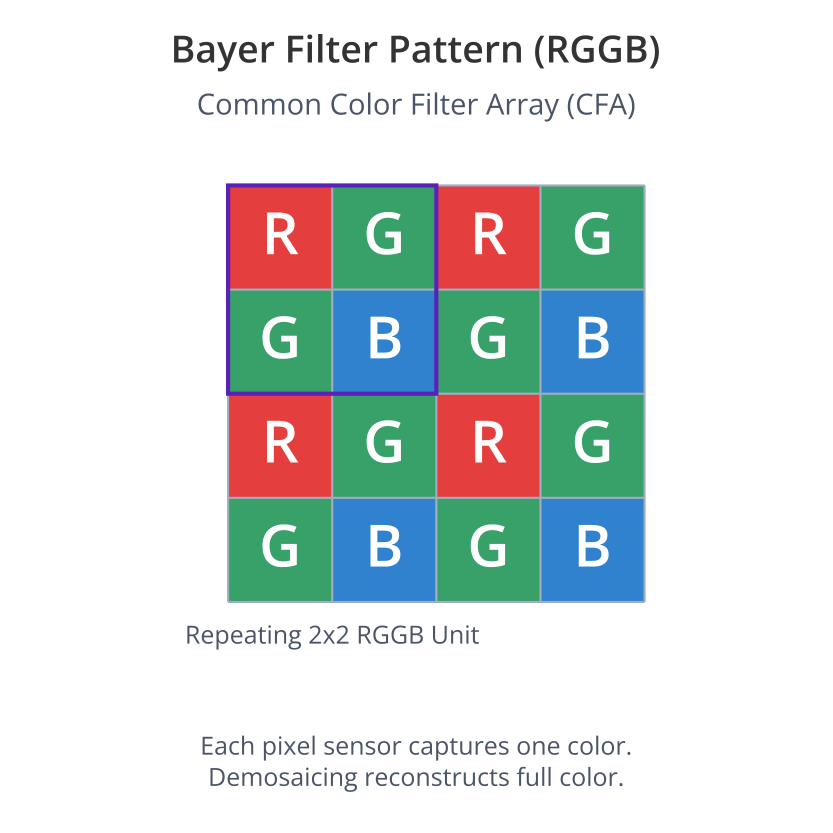
- Color Filter Array (CFA): To capture color images, most sensors use a CFA, typically a Bayer filter pattern. This pattern arranges red, green, and blue filters over alternating pixels. Green is often sampled more frequently as the human eye is most sensitive to it.
- Image Formats:
- RAW: Unprocessed pixel data directly from the sensor after passing through the CFA. Requires demosaicing (interpolation) to reconstruct a full-color image.
- RGB (e.g., RGB565, RGB888): Represents colors as combinations of Red, Green, and Blue intensities. RGB565 (16-bit) is common in embedded systems to save memory.
- YUV (e.g., YUV422, YUV420): Separates luminance (Y, brightness) from chrominance (U and V, color information). Often used in video compression as chrominance can be subsampled without significant perceived loss of quality.
- JPEG (Joint Photographic Experts Group): A compressed image format that significantly reduces file size with some loss of quality. Many camera modules (like the OV2640) have built-in JPEG encoders.
| Image Format | Description | Common Variants | Pros | Cons | Typical Use with ESP32 |
|---|---|---|---|---|---|
| RAW | Unprocessed pixel data directly from the sensor’s CFA. Each pixel has one color value. | Sensor-specific (e.g., RAW8, RAW10, RAW12) |
|
|
Advanced image processing, machine vision where full sensor data is critical. Less common for direct display/streaming due to processing overhead. |
| RGB | Represents colors as Red, Green, and Blue intensity values per pixel. | RGB565 (16-bit), RGB888 (24-bit) |
|
|
RGB565 is common for direct display on TFTs when memory allows, or for simple image processing. Often used by LVGL. |
| YUV | Separates luminance (Y – brightness) from chrominance (U, V – color information). | YUV422, YUV420 (planar/semi-planar) |
|
|
Often an intermediate format from camera sensors before JPEG encoding or for video streaming pipelines. esp_camera supports YUV422. |
| JPEG | Lossy compressed image format. Standardized by Joint Photographic Experts Group. | Baseline JPEG |
|
|
Most common format for ESP32 camera applications: Storing images on SD cards, HTTP streaming (MJPEG), sending over WiFi. Default for many esp_camera examples. |
Camera Interfaces
Microcontrollers communicate with camera sensors/modules using various interfaces:
- Digital Video Port (DVP) / Parallel Interface:
- A common interface for many camera modules like the OV2640 (used on ESP32-CAM).
- Transmits pixel data in parallel (typically 8 data lines: D0-D7).
- Key signals:
PCLK(Pixel Clock): Synchronizes pixel data transfer.HSYNC(Horizontal Sync): Indicates the end of a line of pixels.VSYNC(Vertical Sync): Indicates the end of a frame.XCLK(External Clock/System Clock): Input clock required by the camera module, typically provided by the MCU.SIOC(SCCB Clock) &SIOD(SCCB Data): I2C-like interface (Serial Camera Control Bus) for configuring the camera sensor’s internal registers (e.g., resolution, exposure, white balance).
- The original ESP32 uses its I2S peripheral in camera mode to handle DVP. The ESP32-S3 has a dedicated DVP camera peripheral.
- MIPI CSI-2 (Mobile Industry Processor Interface – Camera Serial Interface 2):
- A high-speed differential serial interface designed for mobile devices.
- Offers higher bandwidth than DVP, suitable for higher resolution and frame rate cameras.
- More complex to interface with directly. Some ESP32-S3 variants include a MIPI CSI host controller.
- SPI (Serial Peripheral Interface) Cameras:
- Simpler interface using standard SPI communication.
- Typically lower resolution and frame rates compared to DVP or MIPI CSI.
- Can be easier to integrate if dedicated camera peripherals are unavailable or GPIOs are limited.
- Often used for very low-cost or specialized camera modules (e.g., ArduCAM Mini).
| Feature | DVP (Digital Video Port) / Parallel | MIPI CSI-2 (Camera Serial Interface 2) | SPI (Serial Peripheral Interface) Cameras |
|---|---|---|---|
| Signal Type | Parallel (single-ended CMOS logic) | Differential Serial (LVDS-like) | Serial (single-ended CMOS logic) |
| Key Signals |
|
|
|
| Bandwidth / Speed | Moderate to High (depends on PCLK, data width) | Very High (scalable with lanes) | Low to Moderate |
| Complexity | Moderate (many pins, timing critical) | High (complex protocol, high-speed signals, impedance matching) | Low (standard SPI, fewer pins) |
| GPIO Pins Required | High (12-18+ pins) | Moderate (fewer than DVP for data, but still needs config bus) | Low (3-4 SPI pins + CS, config pins) |
| ESP32 Support |
|
|
|
| Typical Use Cases | OV2640, OV7670, etc. Common on ESP32-CAM. Good balance for many embedded applications. | Higher resolution/frame rate cameras (e.g., >5MP, >30fps HD) in mobile or advanced vision systems. | Low-resolution, low-cost cameras (e.g., ArduCAM Mini), or when GPIOs are very limited. Simpler projects. |
| Pros |
|
|
|
| Cons |
|
|
|

The ESP32-CAM Board
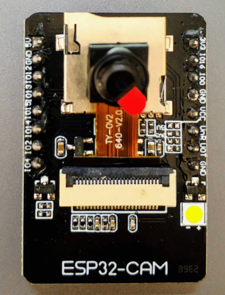
The ESP32-CAM is a popular, low-cost development board based on the ESP32-S module. Its key features relevant to this chapter are:
- ESP32-S Module: Contains an ESP32 dual-core processor.
- OV2640 Camera Module: A 2-megapixel camera sensor commonly included, supporting various resolutions and JPEG compression. Other camera modules like the OV7670 might also be used.
- PSRAM (Pseudo-Static RAM): Typically includes 4MB or 8MB of PSRAM, which is crucial for storing frame buffers, especially for higher resolutions or when using formats like RGB565.
- MicroSD Card Slot: Allows for storing captured images and videos.
- GPIOs: Exposes several GPIOs for other peripherals, though many are used by the camera and SD card.
Warning: The ESP32-CAM board often lacks an onboard USB-to-UART bridge. You typically need an external FTDI programmer or similar to program it and view serial output.
Frame Buffers and PSRAM
A frame buffer is a region of memory used to store the pixel data of a single image frame captured from the camera.
- The size of the frame buffer depends on the resolution and pixel format:
- Example (QQVGA, 160×120, RGB565 – 2 bytes/pixel): 160 * 120 * 2 = 38,400 bytes (approx 37.5 KB).
- Example (SVGA, 800×600, RGB565): 800 * 600 * 2 = 960,000 bytes (approx 937.5 KB).
- Example (UXGA, 1600×1200, JPEG): Size varies greatly due to compression (e.g., 100KB – 300KB).
- The ESP32’s internal SRAM (approx 520KB, with some reserved for the system) is often insufficient for high-resolution frame buffers, especially when also running WiFi and other applications.
- PSRAM is essential for most camera applications on the ESP32, providing several megabytes of additional RAM for frame buffers. The
esp_cameradriver heavily relies on PSRAM.
ESP-IDF Camera Driver (esp_camera.h)
ESP-IDF provides a dedicated camera driver component (esp_camera.h) that simplifies interfacing with common camera modules, particularly those using a DVP interface like the OV2640/OV3660/OV7725 etc.
- Abstraction: Hides many low-level details of I2S configuration (for ESP32) or the DVP controller (for ESP32-S3) and SCCB communication.
- Key Functions:
esp_camera_init(): Initializes the camera with a given configuration structure.esp_camera_deinit(): Deinitializes the camera.esp_camera_capture(): Captures a single frame. (This function is deprecated in newer IDF versions).esp_camera_fb_get(): Acquires a frame buffer from the camera. This is the preferred method.esp_camera_fb_return(): Returns the frame buffer to the driver so it can be reused.sensor_t *s = esp_camera_sensor_get(): Gets a pointer to the sensor structure, allowing access to functions for setting resolution, pixel format, brightness, contrast, special effects, etc. (e.g.,s->set_framesize(s, FRAMESIZE_VGA)).
graph TD
    A[Start: Initialize Camera] --> B("Define <b>camera_config_t</b> <br> - Pin mapping <br> - XCLK frequency <br> - Pixel format (e.g., PIXFORMAT_JPEG) <br> - Frame size (e.g., FRAMESIZE_SVGA) <br> - JPEG quality <br> - Framebuffer count & location (PSRAM)");
    style A fill:#EDE9FE,stroke:#5B21B6,stroke-width:2px,color:#5B21B6
    style B fill:#DBEAFE,stroke:#2563EB,stroke-width:1px,color:#1E40AF

    B --> C{"Call <b>esp_camera_init(&config)</b>"};
    style C fill:#FEF3C7,stroke:#D97706,stroke-width:1px,color:#92400E

    C -- ESP_OK --> D["Camera Initialized <br> (Peripherals configured, sensor detected & set up)"];
    style D fill:#D1FAE5,stroke:#059669,stroke-width:2px,color:#065F46
    C -- Error --> E["Error: Initialization Failed <br> (Check pins, PSRAM, power, sensor)"];
    style E fill:#FEE2E2,stroke:#DC2626,stroke-width:1px,color:#991B1B

    D --> F{"Optional: Get Sensor Handle <br> <b>s = esp_camera_sensor_get()</b>"};
    style F fill:#FEF3C7,stroke:#D97706,stroke-width:1px,color:#92400E
    F -- Yes --> G["Configure Sensor Settings <br> e.g., <b>s->set_brightness(s, 0)</b> <br> <b>s->set_framesize(s, FRAMESIZE_VGA)</b>"];
    style G fill:#DBEAFE,stroke:#2563EB,stroke-width:1px,color:#1E40AF
    G --> H[Ready to Capture];
    F -- No --> H;
    style H fill:#DBEAFE,stroke:#2563EB,stroke-width:1px,color:#1E40AF

    H --> I{"Call <b>esp_camera_fb_get()</b>"};
    style I fill:#FEF3C7,stroke:#D97706,stroke-width:1px,color:#92400E

    I -- Frame Buffer Acquired (fb) --> J["Process Frame Buffer <br> <b>fb->buf</b> (image data) <br> <b>fb->len</b> (data length) <br> (e.g., Save to SD, Send via WiFi)"];
    style J fill:#DBEAFE,stroke:#2563EB,stroke-width:1px,color:#1E40AF
    I -- NULL (Failed) --> K["Error: Frame Buffer Get Failed <br> (Check sensor state, memory)"];
    style K fill:#FEE2E2,stroke:#DC2626,stroke-width:1px,color:#991B1B

    J --> L{"Call <b>esp_camera_fb_return(fb)</b>"};
    style L fill:#FEF3C7,stroke:#D97706,stroke-width:1px,color:#92400E
    L -- Buffer Returned --> M[Frame Buffer Reusable / Freed];
    style M fill:#D1FAE5,stroke:#059669,stroke-width:2px,color:#065F46
    M --> H;


    classDef LStartStyle fill:#EDE9FE,stroke:#5B21B6,stroke-width:1.5px,color:#5B21B6
    classDef LProcessStyle fill:#DBEAFE,stroke:#2563EB,stroke-width:1px,color:#1E40AF
    classDef LDecisionStyle fill:#FEF3C7,stroke:#D97706,stroke-width:1px,color:#92400E
    classDef LSuccessStyle fill:#D1FAE5,stroke:#059669,stroke-width:1.5px,color:#065F46
    classDef LErrorStyle fill:#FEE2E2,stroke:#DC2626,stroke-width:1px,color:#991B1B
The driver typically requires careful pin configuration matching your hardware setup.
Practical Examples
These examples primarily target the ESP32-CAM board with an OV2640 camera or a similar setup using an ESP32/ESP32-S3 with a DVP camera and PSRAM.
Prerequisites:
- ESP-IDF v5.x installed and configured with VS Code.
- An ESP32-CAM board or an ESP32/ESP32-S3 development board with a compatible camera module (e.g., OV2640) and PSRAM, correctly wired.
- An FTDI programmer (or similar) if using ESP32-CAM for flashing and serial monitoring.
Example 1: Basic Image Capture (ESP32-CAM)
This example initializes the camera on an ESP32-CAM, captures a single JPEG image, and prints its size to the serial monitor.
1. Pin Configuration (Common for ESP32-CAM with OV2640):
The esp_camera driver often has pre-defined configurations for popular boards like ESP32-CAM.
// ESP32-CAM (AI-Thinker Model) Pin Configuration
#define CAM_PIN_PWDN    32
#define CAM_PIN_RESET   -1 // NC
#define CAM_PIN_XCLK    0
#define CAM_PIN_SIOD    26
#define CAM_PIN_SIOC    27

#define CAM_PIN_D7      35
#define CAM_PIN_D6      34
#define CAM_PIN_D5      39
#define CAM_PIN_D4      36
#define CAM_PIN_D3      21
#define CAM_PIN_D2      19
#define CAM_PIN_D1      18
#define CAM_PIN_D0       5
#define CAM_PIN_VSYNC   25
#define CAM_PIN_HREF    23 // HSYNC on some modules
#define CAM_PIN_PCLK    22
2. Project Configuration (menuconfig):
- Run
idf.py menuconfig. - Navigate to
Component config—>ESP32-specific(orESPxx-specificfor other chips):- Ensure
Support for external, SPI-connected RAMis enabled. - Set
SPI RAM config—>Initialize SPI RAM when booting up([*]).
- Ensure
- Navigate to
Component config—>Camera Configuration:- You might find options to select a pre-defined camera pinout (e.g., “ESP32-CAM AI-Thinker”). If not, you’ll define pins in code.
- Ensure
Enable ESP32 camera componentis checked.
- Save and exit.
3. Code (main/camera_capture_main.c):
#include <stdio.h>
#include "freertos/FreeRTOS.h"
#include "freertos/task.h"
#include "esp_system.h"
#include "esp_log.h"
#include "esp_camera.h"

static const char *TAG = "CameraCapture";

// ESP32-CAM (AI-Thinker Model) Pin Configuration - ensure these match your board if not using a predefined one
#define CAM_PIN_PWDN    32
#define CAM_PIN_RESET   -1 // NC
#define CAM_PIN_XCLK    0
#define CAM_PIN_SIOD    26
#define CAM_PIN_SIOC    27

#define CAM_PIN_D7      35
#define CAM_PIN_D6      34
#define CAM_PIN_D5      39
#define CAM_PIN_D4      36
#define CAM_PIN_D3      21
#define CAM_PIN_D2      19
#define CAM_PIN_D1      18
#define CAM_PIN_D0       5
#define CAM_PIN_VSYNC   25
#define CAM_PIN_HREF    23
#define CAM_PIN_PCLK    22

static camera_config_t camera_config = {
    .pin_pwdn = CAM_PIN_PWDN,
    .pin_reset = CAM_PIN_RESET,
    .pin_xclk = CAM_PIN_XCLK,
    .pin_sccb_sda = CAM_PIN_SIOD, // Renamed from SIOD for clarity with SCCB
    .pin_sccb_scl = CAM_PIN_SIOC, // Renamed from SIOC

    .pin_d7 = CAM_PIN_D7,
    .pin_d6 = CAM_PIN_D6,
    .pin_d5 = CAM_PIN_D5,
    .pin_d4 = CAM_PIN_D4,
    .pin_d3 = CAM_PIN_D3,
    .pin_d2 = CAM_PIN_D2,
    .pin_d1 = CAM_PIN_D1,
    .pin_d0 = CAM_PIN_D0,
    .pin_vsync = CAM_PIN_VSYNC,
    .pin_href = CAM_PIN_HREF,
    .pin_pclk = CAM_PIN_PCLK,

    // XCLK 20MHz or 10MHz for OV2640 double FPS (Experimental)
    .xclk_freq_hz = 20000000,
    .ledc_timer = LEDC_TIMER_0,
    .ledc_channel = LEDC_CHANNEL_0,

    .pixel_format = PIXFORMAT_JPEG, // YUV422,GRAYSCALE,RGB565,JPEG
    .frame_size = FRAMESIZE_SVGA,   // QQVGA-UXGA Do not use sizes above QVGA when not JPEG

    .jpeg_quality = 12, // 0-63 lower number means higher quality
    .fb_count = 1,      // If more than one, i2s runs in continuous mode. Use only 1 for JPEG
    .grab_mode = CAMERA_GRAB_WHEN_EMPTY, // CAMERA_GRAB_LATEST (deprecated)
    .fb_location = CAMERA_FB_IN_PSRAM, // Framebuffer in PSRAM for larger images
};

void app_main(void)
{
    esp_err_t err = esp_camera_init(&camera_config);
    if (err != ESP_OK) {
        ESP_LOGE(TAG, "Camera Init Failed: 0x%x", err);
        return;
    }
    ESP_LOGI(TAG, "Camera initialized successfully.");

    // Wait a bit for sensor to stabilize
    vTaskDelay(pdMS_TO_TICKS(1000));

    camera_fb_t *fb = esp_camera_fb_get();
    if (!fb) {
        ESP_LOGE(TAG, "Camera Frame Buffer Get Failed");
    } else {
        ESP_LOGI(TAG, "Captured image: %zu bytes, Resolution: %dx%d, Format: %d",
                 fb->len, fb->width, fb->height, fb->format);
        // Here you would process the frame buffer (fb->buf)
        // e.g., save to SD card, send over WiFi, etc.

        esp_camera_fb_return(fb); // Return frame buffer to be reused
        ESP_LOGI(TAG, "Frame buffer returned.");
    }

    // Deinitialize camera (optional, if you are done)
    // esp_camera_deinit();
    // ESP_LOGI(TAG, "Camera deinitialized.");
}
4. CMakeLists.txt (in main directory):
idf_component_register(SRCS "camera_capture_main.c"
                    INCLUDE_DIRS "."
                    REQUIRES esp_camera) # Ensure esp_camera component is linked
5. Build, Flash, and Observe Steps:
- Connect your ESP32-CAM (or custom setup) and FTDI programmer.
- Build the project.
- Flash the project. Remember to put ESP32-CAM into bootloader mode (usually GPIO0 to GND during reset/power-on).
- Open the ESP-IDF Monitor. You should see log messages indicating camera initialization and then details of the captured frame (size, resolution).
Example 2: Simple MJPEG Video Streamer
This example sets up a basic HTTP server on the ESP32 that streams video from the camera as an MJPEG (Motion JPEG) stream, viewable in a web browser.
sequenceDiagram
    participant Client as Web Browser (Client)
    participant ESP32 as ESP32 HTTP Server
    participant Camera as Camera Module
    activate Client
    activate ESP32

    Client->>+ESP32: 1. HTTP GET Request (/stream)
    ESP32->>+Camera: 2. Initialize Camera (if not already)
    Camera-->>-ESP32: Initialization Status

    Note over ESP32: Start HTTP Response
    ESP32->>-Client: 3. Send HTTP 200 OK<br>Content-Type: multipart/x-mixed-replace<br>boundary=--frame

    loop MJPEG Stream Loop
        ESP32->>+Camera: 4. Request Frame (esp_camera_fb_get)
        Camera-->>-ESP32: 5. Frame Buffer (JPEG data)

        alt Frame Captured Successfully
            ESP32->>Client: 6a. Send MJPEG Part Header<br>--frame<br>Content-Type: image/jpeg<br>Content-Length: ...
            ESP32->>Client: 7a. Send JPEG Image Data (fb->buf)
            ESP32->>+Camera: 8a. Return Frame Buffer (esp_camera_fb_return)
            Camera-->>-ESP32: Buffer Returned
        else Frame Capture Failed
            ESP32->>Client: 6b. Send error or close connection
            Note over ESP32: Handle capture failure
        end

        Note over ESP32: Optional delay for frame rate control
        Note over Client,ESP32: Client renders incoming JPEG frames
    end

    Note over Client,ESP32: Connection closes or client navigates away
    ESP32->>-Camera: Optional: Deinitialize camera
Note: A full MJPEG streamer involves significant networking code (WiFi connection, HTTP server). This example will outline the core camera loop and HTTP response part. You’d need to integrate this with a complete HTTP server example from ESP-IDF (e.g.,
protocols/http_server/simple).
Core Logic for MJPEG Stream Handler:
// This is a conceptual snippet for an HTTP GET handler
// Assume 'httpd_req_t *req' is the request object from the HTTP server

// Set HTTP headers for MJPEG stream
httpd_resp_set_type(req, "multipart/x-mixed-replace; boundary=--frame");
// You might need to set other headers like Cache-Control: no-store, Pragma: no-cache, etc.

while (true) {
    camera_fb_t *fb = esp_camera_fb_get();
    if (!fb) {
        ESP_LOGE(TAG, "Camera capture failed");
        // Handle error, maybe break loop or send error response
        break;
    }

    if (fb->format != PIXFORMAT_JPEG) {
        ESP_LOGE(TAG, "MJPEG streaming requires JPEG format. Current format: %d", fb->format);
        esp_camera_fb_return(fb);
        // Handle error
        break;
    }

    char part_buf[128];
    // Send MJPEG frame boundary and content type
    sprintf(part_buf, "\r\n--frame\r\nContent-Type: image/jpeg\r\nContent-Length: %zu\r\n\r\n", fb->len);

    esp_err_t res = httpd_resp_send_chunk(req, part_buf, strlen(part_buf));
    if (res != ESP_OK) {
        esp_camera_fb_return(fb);
        ESP_LOGW(TAG, "Failed to send MJPEG header chunk: 0x%x", res);
        break; // Client likely disconnected
    }

    // Send JPEG image data
    res = httpd_resp_send_chunk(req, (const char *)fb->buf, fb->len);
    if (res != ESP_OK) {
        esp_camera_fb_return(fb);
        ESP_LOGW(TAG, "Failed to send MJPEG data chunk: 0x%x", res);
        break; // Client likely disconnected
    }

    esp_camera_fb_return(fb);

    // Add a small delay if needed to control frame rate or reduce CPU load
    // vTaskDelay(pdMS_TO_TICKS(100)); // e.g., for ~10 FPS

    // Check if client is still connected (implementation depends on HTTP server)
    // if (client_disconnected(req)) break;
}
// httpd_resp_send_chunk(req, NULL, 0); // Finalize response if server requires
To make this work:
- Initialize WiFi and connect to an AP.
- Initialize the camera (as in Example 1, ensuring
PIXFORMAT_JPEG). - Set up an HTTP server using
esp_http_server.h. - Register a GET handler (e.g., for
/stream) that implements the loop above. - Access
http://<ESP32_IP_ADDRESS>/streamin a web browser that supports MJPEG (e.g., Chrome, Firefox).
Tip: The official
esp-whorepository from Espressif contains more advanced camera examples, including robust MJPEG streamers and face recognition applications.
Example 3: Camera DSI
/*
 * SPDX-FileCopyrightText: 2024 Espressif Systems (Shanghai) CO LTD
 *
 * SPDX-License-Identifier: Apache-2.0
 */
#include <stdio.h>
#include <stdlib.h>
#include <string.h>
#include "sdkconfig.h"
#include "esp_attr.h"
#include "esp_log.h"
#include "freertos/FreeRTOS.h"
#include "esp_lcd_mipi_dsi.h"
#include "esp_lcd_panel_ops.h"
#include "esp_ldo_regulator.h"
#include "esp_cache.h"
#include "driver/i2c_master.h"
#include "driver/isp.h"
#include "esp_cam_ctlr_csi.h"
#include "esp_cam_ctlr.h"
#include "example_dsi_init.h"
#include "example_dsi_init_config.h"
#include "example_sensor_init.h"
#include "example_config.h"

static const char *TAG = "cam_dsi";

static bool s_camera_get_new_vb(esp_cam_ctlr_handle_t handle, esp_cam_ctlr_trans_t *trans, void *user_data);
static bool s_camera_get_finished_trans(esp_cam_ctlr_handle_t handle, esp_cam_ctlr_trans_t *trans, void *user_data);

void app_main(void)
{
    esp_err_t ret = ESP_FAIL;
    esp_lcd_dsi_bus_handle_t mipi_dsi_bus = NULL;
    esp_lcd_panel_io_handle_t mipi_dbi_io = NULL;
    esp_lcd_panel_handle_t mipi_dpi_panel = NULL;
    void *frame_buffer = NULL;
    size_t frame_buffer_size = 0;

    //mipi ldo
    esp_ldo_channel_handle_t ldo_mipi_phy = NULL;
    esp_ldo_channel_config_t ldo_mipi_phy_config = {
        .chan_id = CONFIG_EXAMPLE_USED_LDO_CHAN_ID,
        .voltage_mv = CONFIG_EXAMPLE_USED_LDO_VOLTAGE_MV,
    };
    ESP_ERROR_CHECK(esp_ldo_acquire_channel(&ldo_mipi_phy_config, &ldo_mipi_phy));

    /**
     * @background
     * Sensor use RAW8
     * ISP convert to RGB565
     */
    //---------------DSI Init------------------//
    example_dsi_resource_alloc(&mipi_dsi_bus, &mipi_dbi_io, &mipi_dpi_panel, &frame_buffer);

    //---------------Necessary variable config------------------//
    frame_buffer_size = CONFIG_EXAMPLE_MIPI_CSI_DISP_HRES * CONFIG_EXAMPLE_MIPI_DSI_DISP_VRES * EXAMPLE_RGB565_BITS_PER_PIXEL / 8;

    ESP_LOGD(TAG, "CONFIG_EXAMPLE_MIPI_CSI_DISP_HRES: %d, CONFIG_EXAMPLE_MIPI_DSI_DISP_VRES: %d, bits per pixel: %d", CONFIG_EXAMPLE_MIPI_CSI_DISP_HRES, CONFIG_EXAMPLE_MIPI_DSI_DISP_VRES, 8);
    ESP_LOGD(TAG, "frame_buffer_size: %zu", frame_buffer_size);
    ESP_LOGD(TAG, "frame_buffer: %p", frame_buffer);

    esp_cam_ctlr_trans_t new_trans = {
        .buffer = frame_buffer,
        .buflen = frame_buffer_size,
    };

    //--------Camera Sensor and SCCB Init-----------//
    i2c_master_bus_handle_t i2c_bus_handle = NULL;
    example_sensor_init(I2C_NUM_0, &i2c_bus_handle);

    //---------------CSI Init------------------//
    esp_cam_ctlr_csi_config_t csi_config = {
        .ctlr_id = 0,
        .h_res = CONFIG_EXAMPLE_MIPI_CSI_DISP_HRES,
        .v_res = CONFIG_EXAMPLE_MIPI_CSI_DISP_VRES,
        .lane_bit_rate_mbps = EXAMPLE_MIPI_CSI_LANE_BITRATE_MBPS,
        .input_data_color_type = CAM_CTLR_COLOR_RAW8,
        .output_data_color_type = CAM_CTLR_COLOR_RGB565,
        .data_lane_num = 2,
        .byte_swap_en = false,
        .queue_items = 1,
    };
    esp_cam_ctlr_handle_t cam_handle = NULL;
    ret = esp_cam_new_csi_ctlr(&csi_config, &cam_handle);
    if (ret != ESP_OK) {
        ESP_LOGE(TAG, "csi init fail[%d]", ret);
        return;
    }

    esp_cam_ctlr_evt_cbs_t cbs = {
        .on_get_new_trans = s_camera_get_new_vb,
        .on_trans_finished = s_camera_get_finished_trans,
    };
    if (esp_cam_ctlr_register_event_callbacks(cam_handle, &cbs, &new_trans) != ESP_OK) {
        ESP_LOGE(TAG, "ops register fail");
        return;
    }

    ESP_ERROR_CHECK(esp_cam_ctlr_enable(cam_handle));

    //---------------ISP Init------------------//
    isp_proc_handle_t isp_proc = NULL;
    esp_isp_processor_cfg_t isp_config = {
        .clk_hz = 80 * 1000 * 1000,
        .input_data_source = ISP_INPUT_DATA_SOURCE_CSI,
        .input_data_color_type = ISP_COLOR_RAW8,
        .output_data_color_type = ISP_COLOR_RGB565,
        .has_line_start_packet = false,
        .has_line_end_packet = false,
        .h_res = CONFIG_EXAMPLE_MIPI_CSI_DISP_HRES,
        .v_res = CONFIG_EXAMPLE_MIPI_CSI_DISP_VRES,
    };
    ESP_ERROR_CHECK(esp_isp_new_processor(&isp_config, &isp_proc));
    ESP_ERROR_CHECK(esp_isp_enable(isp_proc));

    //---------------DPI Reset------------------//
    example_dpi_panel_reset(mipi_dpi_panel);

    //init to all white
    memset(frame_buffer, 0xFF, frame_buffer_size);
    esp_cache_msync((void *)frame_buffer, frame_buffer_size, ESP_CACHE_MSYNC_FLAG_DIR_C2M);

    if (esp_cam_ctlr_start(cam_handle) != ESP_OK) {
        ESP_LOGE(TAG, "Driver start fail");
        return;
    }

    example_dpi_panel_init(mipi_dpi_panel);

    while (1) {
        ESP_ERROR_CHECK(esp_cam_ctlr_receive(cam_handle, &new_trans, ESP_CAM_CTLR_MAX_DELAY));
    }
}

static bool s_camera_get_new_vb(esp_cam_ctlr_handle_t handle, esp_cam_ctlr_trans_t *trans, void *user_data)
{
    esp_cam_ctlr_trans_t new_trans = *(esp_cam_ctlr_trans_t *)user_data;
    trans->buffer = new_trans.buffer;
    trans->buflen = new_trans.buflen;

    return false;
}

static bool s_camera_get_finished_trans(esp_cam_ctlr_handle_t handle, esp_cam_ctlr_trans_t *trans, void *user_data)
{
    return false;
}
Variant Notes
Camera support varies significantly across ESP32 variants:
| ESP32 Variant | Key Camera Interface Support | PSRAM Availability | esp_camera Component Suitability | Typical Camera Use Cases |
|---|---|---|---|---|
| ESP32 (Original) |
|
Commonly available (e.g., ESP32-WROVER, ESP32-CAM) – Essential | Excellent (Primarily designed for DVP on ESP32 via I2S) | ESP32-CAM style projects, MJPEG streaming, basic machine vision. |
| ESP32-S2 |
|
Available on some modules. | Not directly suitable for DVP cameras. Use generic SPI drivers for SPI cameras. | Primarily SPI-based cameras. DVP camera integration is complex/limited. |
| ESP32-S3 |
|
Commonly available and often larger capacities – Highly Recommended | Excellent (Supports DVP via LCD_CAM peripheral) | Higher performance camera apps, AI vision, larger resolution/frame rates, MIPI cameras (on specific S3 chips). |
| ESP32-C3 |
|
Not typically present. | Not applicable for DVP. Use generic SPI for SPI cameras. | Low-power, simpler applications with SPI cameras. Resource-constrained. |
| ESP32-C6 |
|
Not typically present. | Not applicable for DVP. Use generic SPI for SPI cameras. | IoT applications with SPI cameras where camera is secondary. Resource-constrained. |
| ESP32-H2 |
|
Not typically present. | Not applicable for DVP. Use generic SPI for SPI cameras. | Low-power wireless applications with simple SPI camera needs. Resource-constrained. |
- ESP32 (Original):
- Uses the I2S peripheral in camera mode to interface with DVP cameras (like OV2640).
- Requires PSRAM for decent performance and resolutions.
- The
esp_cameracomponent is primarily designed and tested for this setup. - Well-suited for ESP32-CAM style applications.
- ESP32-S2:
- Does not have the same I2S camera interface as the original ESP32.
- Lacks a dedicated DVP parallel camera peripheral.
- Interfacing parallel cameras like OV2640 is significantly more complex or not directly feasible without bit-banging (very slow) or external hardware.
- Primarily suited for SPI-based cameras if camera functionality is needed. The
esp_cameracomponent is not designed for SPI cameras. You would use generic SPI drivers and a camera-specific library for SPI cameras.
- ESP32-S3:
- Offers the best camera support in the ESP32 family.
- Includes a dedicated DVP camera peripheral (LCD_CAM), which is more efficient than using I2S.
- Some ESP32-S3 variants also feature a MIPI CSI-2 host controller, allowing interface with MIPI cameras (though driver support might be more specialized).
- The
esp_cameracomponent can be configured to use the ESP32-S3’s DVP peripheral. - Often comes with larger PSRAM options.
- Ideal for higher-performance camera applications.
- ESP32-C3 / ESP32-C6 / ESP32-H2 (RISC-V and newer Arm):
- Generally do not have dedicated parallel camera interfaces (DVP or I2S for camera).
- These are more resource-constrained and are typically targeted for less demanding applications.
- If camera functionality is required, SPI-based cameras are the most viable option. This would require custom driver integration or third-party libraries for the specific SPI camera module, as
esp_camerais not for SPI cameras. - Performance will be limited compared to ESP32 or ESP32-S3 with parallel cameras.
Common Mistakes & Troubleshooting Tips
| Mistake / Issue | Symptom(s) | Troubleshooting / Solution |
|---|---|---|
| Incorrect Pin Wiring/Definition |
|
|
| PSRAM Not Enabled / Working |
|
|
| Insufficient Power Supply |
|
|
| XCLK (Camera Clock) Issues |
|
|
| SCCB (I2C-like) Communication Failure |
|
|
| Camera Module Not Detected or Faulty |
|
|
| Frame Buffer Issues |
|
|
| MJPEG Streaming Issues |
|
|
Exercises
- Change Camera Settings:
- Modify Example 1 to experiment with different frame sizes (
FRAMESIZE_QVGA,FRAMESIZE_VGA, etc.) and JPEG quality settings (jpeg_quality). Observe the impact on captured image size (fb->len) and visual quality (if you save/display the image). - Try setting special effects available in the sensor (e.g.,
s->set_special_effect(s, 2); // Grayscale). Consultesp_camera.hor sensor datasheet for effect codes.
- Modify Example 1 to experiment with different frame sizes (
- Save Image to SD Card (ESP32-CAM):
- Extend Example 1 to save the captured JPEG image to an SD card.
- Initialize the SD card using the SPI interface (refer to Chapter 150: SD Card and SDIO Interface).
- After
esp_camera_fb_get(), open a new file on the SD card (e.g.,image.jpg) and write the contents offb->buf(with lengthfb->len) to the file. - Remember to close the file and return the frame buffer.
- Basic LED Flash for Camera:
- Connect an LED to a free GPIO on your ESP32-CAM (many boards have an onboard flash LED, often on GPIO4).
- Modify Example 1 to turn on the LED just before calling
esp_camera_fb_get()and turn it off immediately after. This simulates a simple flash.
- HTTP Server for Still Image Capture:
- Instead of streaming, create an HTTP server with an endpoint (e.g.,
/capture). - When this endpoint is requested via a web browser, capture a single JPEG image using
esp_camera_fb_get(). - Send this single JPEG image back as the HTTP response with
Content-Type: image/jpeg. - The browser should display the captured still image.
- Instead of streaming, create an HTTP server with an endpoint (e.g.,
Summary
- The ESP32 (original) and ESP32-S3 are well-suited for camera applications using DVP parallel cameras, leveraging the
esp_cameracomponent and PSRAM. - ESP32-CAM is a popular board packaging an ESP32, OV2640 camera, and PSRAM.
- The
esp_camera.hdriver simplifies camera initialization, configuration, and frame capture. - Key camera parameters include resolution (frame size), pixel format (JPEG, RGB565, YUV), and JPEG quality.
- PSRAM is crucial for storing frame buffers, especially for higher resolutions.
- MJPEG streaming is a common method to transmit live video over HTTP.
- ESP32-S2, ESP32-C3, ESP32-C6, and ESP32-H2 have limited or no direct support for parallel cameras and would typically rely on SPI cameras, requiring different drivers.
- Successful camera integration requires careful attention to pin configuration, power supply, XCLK, and PSRAM.
Further Reading
- ESP-IDF Programming Guide – Camera:
- https://docs.espressif.com/projects/esp-idf/en/v5.4/esp32/api-reference/peripherals/camera.html (Also check ESP32-S3 specific camera docs if available).
esp_camera.hHeader File:- Located in your ESP-IDF components directory (
components/esp_camera/include/esp_camera.h). Contains definitions forcamera_config_t, frame sizes, pixel formats, and sensor control functions.
- Located in your ESP-IDF components directory (
- ESP32-CAM Product Pages and Schematics: (Search for AI-Thinker ESP32-CAM schematic for pin details).
- OV2640 Datasheet: (Available online from OmniVision or sensor resellers). Provides detailed information about the sensor’s registers and capabilities.
- ESP-WHO – ESP32 Human Face Detection and Recognition Framework:
- https://github.com/espressif/esp-who (Contains advanced camera applications and optimized drivers).
- ESP32 Camera Examples in ESP-IDF:
