
Chapter 29: C for Embedded Systems: Structures, Unions, and Bitfields
Chapter Objectives
By the end of this chapter, you will be able to:
- Understand the fundamental differences between structures and unions and identify appropriate use cases for each in an embedded context.
- Analyze and predict the memory layout of C structures, including the effects of data alignment and padding.
- Implement bitfields to create C structures that precisely map to the layout of hardware control and status registers.
- Develop C programs that use structures, unions, and bitfields to interact with memory-mapped peripherals in a readable, maintainable, and efficient manner.
- Debug common issues related to data structure alignment, endianness, and compiler-specific behavior in cross-platform embedded development.
- Apply these advanced data structuring techniques to write clean, efficient, and portable C code for the Raspberry Pi 5 and other embedded Linux systems.
Introduction
In our journey through embedded Linux, we have explored the shell, compiled programs, and interacted with the system at a high level. Now, we descend closer to the hardware, into the domain where the C programming language reigns supreme. While you may have encountered C in general-purpose software development, its application in embedded systems is a more demanding discipline. Here, efficiency is not just a goal; it is a necessity. Memory is not an abstract, near-infinite resource; it is a finite, precious commodity, and every byte counts.
This chapter revisits and expands upon three of C’s most powerful data-structuring features: structures (struct), unions (union), and bitfields. These are the primary tools a C programmer uses to impose order on memory. In the world of embedded systems, this is not merely an organizational task. It is the fundamental mechanism for communicating with hardware. Peripherals—from simple GPIO pins to complex network controllers—expose their functionality through registers, which are specific memory addresses with a precisely defined layout. To control a device, you must write specific values to specific bits at a specific address. This chapter will teach you how to model those hardware registers directly in your C code, transforming cryptic bitwise operations on raw addresses into clean, self-documenting, and efficient interactions with complex data structures. By mastering these concepts, you will move beyond writing applications for an embedded system and begin writing software that controls the system.
Technical Background
The Structure (struct): Organizing Heterogeneous Data
At its core, a C structure, declared with the struct keyword, is a composite data type that groups together variables of potentially different types under a single name. This provides a logical way to manage related data. For instance, representing an employee might involve grouping their ID (an integer), salary (a float), and name (a character array). In an embedded system, a struct might represent a sensor, grouping its I2C address, a file descriptor for communication, and a buffer for its most recent reading.
The true power of structures in embedded programming, however, lies in their memory layout. When you define a structure, the C standard guarantees that its members are allocated in memory in the order they are declared. This sequential layout is the foundation upon which we build interfaces to hardware.
Consider a simple structure:
struct SensorReading {
    unsigned short id;      // 2 bytes
    unsigned int timestamp; // 4 bytes
    float value;            // 4 bytes
};
One might naively assume this structure occupies exactly 2 + 4 + 4 = 10 bytes of memory. However, running sizeof(struct SensorReading) will likely report 12 bytes. This discrepancy is due to a critical concept known as data alignment and padding.
Data Alignment and Padding: The Hidden Rules of Memory
Modern processors, including the ARM Cortex-A76 on the Raspberry Pi 5, do not read memory one byte at a time. They fetch data in larger chunks, typically 4 or 8 bytes, called a word. For the CPU to access data most efficiently, the data’s memory address should be a multiple of its size. For example, a 4-byte integer should ideally start at an address divisible by 4 (e.g., 0x1000, 0x1004, 0x1008). Accessing a 4-byte integer at an unaligned address, say 0x1001, would force the CPU to perform two memory fetches and then internally shift and combine the bytes, incurring a significant performance penalty. On some architectures, it results in a hardware exception.
To prevent this, the C compiler automatically enforces alignment by inserting unused bytes, known as padding, between structure members. Let’s re-examine our SensorReading structure. The id member is 2 bytes. The next member, timestamp, is a 4-byte integer. To ensure timestamp is aligned to a 4-byte boundary, the compiler inserts 2 bytes of padding after id. The structure’s memory layout now looks like this:
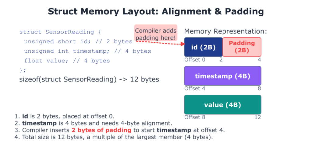
The id (2 bytes) is placed at offset 0. The next member, timestamp (4 bytes), needs to be on a 4-byte boundary. The compiler pads with 2 bytes to start timestamp at offset 4. value (4 bytes) naturally follows at offset 8, which is a 4-byte boundary, so no padding is needed between timestamp and value. Finally, the total size of the structure itself is often padded to be a multiple of the size of its largest member. Here, the largest member is 4 bytes, and the current size is 12 bytes, which is a multiple of 4, so no trailing padding is needed. The result is a total size of 12 bytes, not 10.
This automatic behavior is usually helpful, but in embedded systems, where we must match a hardware-defined memory map, it can be a problem. Hardware does not add padding. To solve this, compilers provide mechanisms to control padding. With GCC and Clang, you can use the __attribute__((packed)) directive:
struct PackedSensorReading {
    unsigned short id;
    unsigned int timestamp;
    float value;
} __attribute__((packed));
Now, sizeof(struct PackedSensorReading) will report 10 bytes. The compiler has been instructed to remove all padding, arranging the members contiguously in memory. This is essential for creating data structures that will be sent over a network or used to map directly onto a hardware register block, but it comes at the cost of potential performance degradation due to unaligned access. This trade-off between memory size and access speed is a constant theme in embedded development.
The Union (union): One Memory Space, Many Interpretations
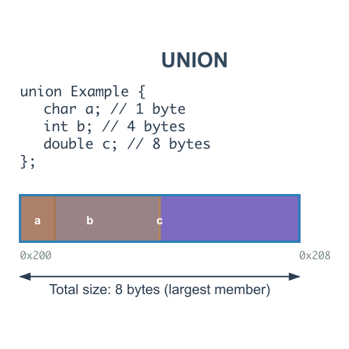
A union, like a structure, is a composite data type. The crucial difference is that while a struct allocates enough space to store all its members, a union allocates only enough space to store its largest member. All members of a union share the same memory location, starting at the same address. This means you can only store a value in one member at a time. Writing to one member will overwrite the data of all other members.
This might seem restrictive, but it provides powerful capabilities. One common use case is to create a variant type, where a data structure needs to hold one of several different types of values, but never at the same time. For example, a message packet in a communication protocol might have a payload that could be a command, a status update, or a data sample. A union allows this to be represented memory-efficiently.
struct ProtocolPacket {
    unsigned char message_type;
    union {
        unsigned int command_id;
        float sensor_value;
        char error_message[16];
    } payload;
};
I
n this example, the size of the payload union is the size of its largest member, error_message (16 bytes). The message_type field acts as a tag, indicating which member of the union is currently valid.
A more “classic” embedded use of unions is for type punning: reinterpreting the bits of one data type as another. For example, you might receive a 32-bit floating-point number from a sensor but need to transmit it byte-by-byte over a serial interface. A union provides an elegant way to do this without complex pointer casting and potential violations of C’s strict aliasing rules.
union FloatConverter {
    float f_val;
    unsigned char bytes[4];
};

// Usage:
union FloatConverter converter;
converter.f_val = 3.14159f;
// Now, converter.bytes[0] through converter.bytes[3] can be accessed
// to get the raw byte representation of the float.
graph TD


    A(Start: Convert Float to Bytes) --> B{union FloatConverter cvt; <br> cvt.f_val = 3.14;};
    B --> C{"Access cvt.bytes[0..3]"};
    C --> D{System Endianness?};

    D -- "Little-Endian (e.g., x86, ARM)" --> LE_MEM(Memory: LSB at Lowest Address);
    LE_MEM --> LE_BYTES["`<b>cvt.bytes</b><br>[0] [1] [2] [3]<br>C3 F5 48 40`"]:::system;
    LE_BYTES --> LE_RESULT("Result: Least Significant Byte (LSB) is first."):::success;

    D -- "Big-Endian (e.g., PowerPC, Network)" --> BE_MEM(Memory: MSB at Lowest Address);
    BE_MEM --> BE_BYTES["`<b>cvt.bytes</b><br>[0] [1] [2] [3]<br>40 48 F5 C3`"]:::system;
    BE_BYTES --> BE_RESULT("Result: Most Significant Byte (MSB) is first."):::success;

    subgraph Explanation
        direction TB
        W1(Warning) --> W2("The byte order is reversed between systems!"):::warning;
        W2 --> W3("Code relying on this is NOT portable without checks."):::check;
    end

    classDef primary fill:#1e3a8a,stroke:#1e3a8a,stroke-width:2px,color:#ffffff;
    classDef success fill:#10b981,stroke:#10b981,stroke-width:2px,color:#ffffff;
    classDef process fill:#0d9488,stroke:#0d9488,stroke-width:1px,color:#ffffff;
    classDef check fill:#ef4444,stroke:#ef4444,stroke-width:1px,color:#ffffff;
    classDef system fill:#8b5cf6,stroke:#8b5cf6,stroke-width:1px,color:#ffffff;
    classDef warning fill:#eab308,stroke:#eab308,stroke-width:1px,color:#1f2937;

    class A,L1 primary;
    class B,L2 process;
    class LE_BYTES,BE_BYTES,L3 system;
    class C,W3,L4 check;
    class D,W1 decision;
    class LE_MEM,BE_MEM process;
    class LE_RESULT,BE_RESULT success;
    class W2 warning;
Warning: The behavior of type punning with unions depends on the system’s endianness—the order in which bytes are arranged in memory. On a little-endian system (like ARM and x86), the least significant byte is stored at the lowest memory address. On a big-endian system, the most significant byte is stored first. The code above will produce different byte arrays on systems with different endianness, a critical portability concern.
Bitfields: The Ultimate Control
We now arrive at the most granular level of memory control C offers: bitfields. Bitfields are a special feature of struct and union declarations that allow you to define members that occupy a specific number of bits. This is the single most important tool for mapping a C structure directly onto a hardware register.
Hardware peripherals are controlled by writing to and reading from registers, which are typically 8, 16, or 32 bits wide. Each bit or group of bits within a register has a specific meaning. For example, a UART (Universal Asynchronous Receiver/Transmitter) control register might look like this:
Without bitfields, interacting with this register would be a messy affair involving bitwise shifts and masks:
// To enable the UART and set baud rate to 3 (binary 011)
unsigned short control_reg = 0;
control_reg |= (1 << 15);       // Set UARTEN
control_reg |= (1 << 14);       // Set TXEN
control_reg |= (3 << 10);       // Set BAUD to 3
This code is error-prone and difficult to read. A small typo in a bit position could lead to hours of debugging. Bitfields allow us to create a C structure that mirrors this layout perfectly:
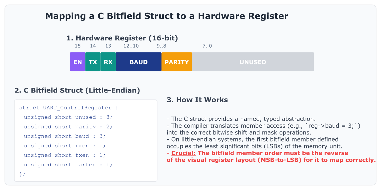
struct UART_ControlRegister {
    // The order is from least significant bit to most significant bit
    // on a little-endian architecture.
    unsigned short unused : 8;
    unsigned short parity : 2;
    unsigned short baud   : 3;
    unsigned short rxen   : 1;
    unsigned short txen   : 1;
    unsigned short uarten : 1;
};
The syntax type member_name : width; defines a bitfield member. Now, we can interact with the register in a much more intuitive and self-documenting way:
// Assuming 'p_uart_ctrl' is a pointer to the hardware register address
// cast to our struct type.
struct UART_ControlRegister* p_uart_ctrl = (struct UART_ControlRegister*)0xADDRESS;

p_uart_ctrl->uarten = 1;
p_uart_ctrl->txen = 1;
p_uart_ctrl->baud = 3;
This code is not only cleaner but also safer. The compiler handles the generation of the correct bitwise instructions. If you try to assign a value too large for the field (e.g., p_uart_ctrl->baud = 10;, which requires 4 bits), the compiler will truncate it and likely issue a warning.
Warning: The layout of bitfields in memory is one of the most implementation-defined areas of the C language. Factors like bit-packing order (left-to-right or right-to-left) and how bitfields cross storage unit boundaries (e.g., a byte boundary) can vary between compilers and architectures. When writing code that relies on a specific bitfield layout for hardware interaction, it is absolutely essential to consult your compiler’s documentation and test thoroughly on the target hardware. For truly portable code, some style guides (like the Linux kernel’s) forbid bitfields and mandate the use of explicit bitwise masks and shifts. However, for a specific, known target like the Raspberry Pi 5 with GCC, they are an invaluable tool for clarity.
Practical Examples
Theory is essential, but understanding comes from application. We will now apply these concepts to a practical scenario on the Raspberry Pi 5. We will pretend we are writing a driver for a fictional I2C environmental sensor, the “ENV-PRO,” which has a set of configuration and data registers.
Our goal is to create a C program that defines the sensor’s register map using struct, union, and bitfields, and then uses these definitions to configure the sensor and read data from it. While we won’t be using a real device, we will simulate the interaction by allocating memory and using pointers, mimicking how a real driver would interact with memory-mapped I/O.
The ENV-PRO Sensor Register Map
The datasheet for our fictional sensor specifies the following registers at its I2C address:
- Config Register (Offset
0x00, 16-bit, R/W):- Bits 15-14:
MODE(00=Sleep, 01=Temp only, 10=Humidity only, 11=Temp & Humidity) - Bit 13:
HEATER(0=Off, 1=On) - Bits 12-10:
OSR_H(Humidity Oversampling: 0 to 7) - Bits 9-7:
OSR_T(Temperature Oversampling: 0 to 7) - Bits 6-0:
RESERVED
- Bits 15-14:
- Device ID Register (Offset
0x02, 8-bit, R/O):- Should always read
0xDA.
- Should always read
- Data Registers (Offset
0x03, 48-bit, R/O):- A block of 6 bytes containing both temperature and humidity readings.
- Bytes 0-2:
TEMP(24-bit unsigned integer, raw temperature) - Bytes 3-5:
HUMID(24-bit unsigned integer, raw humidity)
Step 1: Defining the Register Map in C
First, let’s create a header file, env_pro.h, to define the register layout using the C features we’ve discussed. We will use a packed structure to ensure our memory map matches the hardware exactly.
File: env_pro.h
#ifndef ENV_PRO_H
#define ENV_PRO_H

#include <stdint.h> // For fixed-width integer types like uint16_t

// Use a bitfield struct to represent the configuration register.
// The order of members is defined from LSB to MSB for clarity on
// little-endian systems like the Raspberry Pi's ARM core.
typedef struct {
    uint16_t reserved : 7;
    uint16_t osr_t    : 3; // Temperature oversampling
    uint16_t osr_h    : 3; // Humidity oversampling
    uint16_t heater   : 1;
    uint16_t mode     : 2;
} __attribute__((packed)) config_reg_t;

// The data registers contain two 24-bit values. C doesn't have a native
// uint24_t, so we represent them as 3-byte arrays.
typedef struct {
    uint8_t temp[3];
    uint8_t humid[3];
} __attribute__((packed)) data_regs_t;

// Now, we combine all registers into a single structure that represents
// the entire memory map of the device. This is a common driver technique.
// We use a union to overlay the config_reg_t bitfield onto a simple
// uint16_t, allowing us to write to the register as a whole or bit-by-bit.
typedef struct {
    union {
        config_reg_t fields; // Access individual bitfields
        uint16_t     value;  // Access the whole 16-bit register
    } config;

    uint8_t device_id;

    data_regs_t data;

} __attribute__((packed)) env_pro_regs_t;


// Function to convert the 24-bit raw temperature reading into a float
static inline float convert_temp(const uint8_t raw[3]) {
    // On little-endian, raw[0] is LSB, raw[2] is MSB.
    int32_t temp_raw = (raw[2] << 16) | (raw[1] << 8) | raw[0];
    // Example conversion formula from datasheet
    return (float)temp_raw / 100.0f;
}

// Function to convert the 24-bit raw humidity reading into a float
static inline float convert_humid(const uint8_t raw[3]) {
    int32_t humid_raw = (raw[2] << 16) | (raw[1] << 8) | raw[0];
    // Example conversion formula from datasheet
    return (float)humid_raw / 1024.0f;
}

#endif // ENV_PRO_H
Explanation:
- We use
__attribute__((packed))on all our structures to prevent compiler padding. This is non-negotiable when mapping to hardware. - The
config_reg_tuses bitfields to precisely match the layout of the configuration register. - The
data_regs_tuses arrays ofuint8_tto represent the 24-bit data values. - The main structure,
env_pro_regs_t, is the key. It contains aunionfor the config register. This is a powerful pattern: it allows a programmer to easily set the entire register with a single 16-bit write (regs->config.value = 0x8A00;) for initial setup, and then tweak individual settings (regs->config.fields.heater = 1;) during operation. - We’ve included
static inlinehelper functions to process the raw data, encapsulating the conversion logic.
Step 2: Simulating the Device and Writing the Driver Logic
Now, let’s write a C program, main.c, that uses our header file. In a real scenario, the p_sensor pointer would be initialized with the memory address returned by mmap() for a device file. Here, we will use malloc() to simulate that memory block.
File: main.c
#include <stdio.h>
#include <stdlib.h>
#include <string.h>
#include "env_pro.h"

int main() {
    printf("Embedded C Data Structures Demo\n");

    // --- 1. Device Simulation Setup ---
    // In a real driver, this memory would be mapped from the device.
    // Here, we allocate it on the heap to simulate.
    env_pro_regs_t* p_sensor = (env_pro_regs_t*)malloc(sizeof(env_pro_regs_t));
    if (!p_sensor) {
        perror("Failed to allocate memory for sensor simulation");
        return 1;
    }

    // Initialize the simulated device with some default power-on values.
    memset(p_sensor, 0, sizeof(env_pro_regs_t));
    p_sensor->device_id = 0xDA; // The correct device ID.

    // Pre-load some fake sensor data into the data registers.
    // Temp: 2500 -> 25.00 C. 2500 = 0x09C4.
    p_sensor->data.temp[0] = 0xC4;
    p_sensor->data.temp[1] = 0x09;
    p_sensor->data.temp[2] = 0x00;

    // Humidity: 46080 -> 45.0%. 46080 = 0xB400.
    p_sensor->data.humid[0] = 0x00;
    p_sensor->data.humid[1] = 0xB4;
    p_sensor->data.humid[2] = 0x00;


    // --- 2. Verify Device and Initial State ---
    printf("Checking device ID... ");
    if (p_sensor->device_id == 0xDA) {
        printf("OK (0x%X)\n", p_sensor->device_id);
    } else {
        printf("FAIL! (Expected 0xDA, got 0x%X)\n", p_sensor->device_id);
        free(p_sensor);
        return 1;
    }

    printf("Initial Config Register Value: 0x%04X\n", p_sensor->config.value);
    printf("Size of register map struct: %zu bytes\n", sizeof(env_pro_regs_t));


    // --- 3. Configure the Device using Bitfields ---
    printf("\nConfiguring sensor...\n");
    // We will set Mode=Temp&Humid (11), Heater=On (1), OSR_H=x4 (100), OSR_T=x2 (010)
    p_sensor->config.fields.mode = 3;   // Binary 11
    p_sensor->config.fields.heater = 1;
    p_sensor->config.fields.osr_h = 4;  // Binary 100
    p_sensor->config.fields.osr_t = 2;  // Binary 010

    printf("Configuration complete.\n");
    printf("New Config Register Value:   0x%04X\n", p_sensor->config.value);

    // --- 4. Read and Interpret Data ---
    printf("\nReading sensor data...\n");
    float temperature = convert_temp(p_sensor->data.temp);
    float humidity = convert_humid(p_sensor->data.humid);

    printf("  Temperature: %.2f C\n", temperature);
    printf("  Humidity:    %.1f %%\n", humidity);

    // --- 5. Cleanup ---
    free(p_sensor);
    return 0;
}
flowchart TD
    A(Start) --> B[Simulate Device <br>  malloc  memory for  env_pro_regs_t ];
    B --> C{Memory allocated?};
    C -- No --> C_FAIL(Exit with error)
    C -- Yes --> D[Initialize Simulated Device <br>  memset  to zero <br> Set  device_id = 0xDA  <br> Pre-load fake sensor data];

    D --> E{Verify Device ID <br>  p_sensor->device_id == 0xDA ?};
    E -- No --> E_FAIL(Exit with error);
    E -- Yes --> F[Print Initial State <br>  config.value  and  sizeof ];

    F --> G[Configure Device <br> Use bitfields to set mode, <br> heater, and oversampling <br>  p_sensor->config.fields.mode = 3; ];
    G --> H[Print New Config Value <br>  p_sensor->config.value ];

    H --> I["Read & Interpret Data <br> Call  convert_temp()  <br> Call  convert_humid() "];
    I --> J[Print Formatted Results <br> Temperature and Humidity];
    J --> K["Cleanup <br>  free(p_sensor) "];
    K --> L(End);

    classDef primary fill:#1e3a8a,stroke:#1e3a8a,stroke-width:2px,color:#ffffff;
    classDef success fill:#10b981,stroke:#10b981,stroke-width:2px,color:#ffffff;
    classDef decision fill:#f59e0b,stroke:#f59e0b,stroke-width:1px,color:#ffffff;
    classDef process fill:#0d9488,stroke:#0d9488,stroke-width:1px,color:#ffffff;
    classDef check fill:#ef4444,stroke:#ef4444,stroke-width:1px,color:#ffffff;
    classDef system fill:#8b5cf6,stroke:#8b5cf6,stroke-width:1px,color:#ffffff;

    class A,L primary;
    class K,J,I,G,F,D,B process;
    class C,E decision;
    class C_FAIL,E_FAIL check;
    class H system;
Step 3: Build and Run
On your Linux development host (e.g., Ubuntu), you would typically cross-compile this for the Raspberry Pi.
Makefile:
# Makefile for cross-compiling for Raspberry Pi 5 (aarch64)
# Assumes a cross-compiler toolchain is installed and in the PATH.
# Example: arm-linux-gnueabihf-gcc or aarch64-linux-gnu-gcc

# The target architecture prefix
CROSS_COMPILE ?= aarch64-linux-gnu-

CC = $(CROSS_COMPILE)gcc
TARGET = env_pro_driver_sim
OBJS = main.o
CFLAGS = -Wall -Wextra -O2 -g

.PHONY: all clean

all: $(TARGET)

$(TARGET): $(OBJS)
	$(CC) $(CFLAGS) -o $@ $^

%.o: %.c env_pro.h
	$(CC) $(CFLAGS) -c $< -o $@

clean:
	rm -f $(TARGET) $(OBJS)
Build, Deploy, and Run Steps:
1. Build: On your development machine, ensure you have the AArch64 cross-compiler installed. Then simply run make.
make2. Deploy: Copy the compiled binary env_pro_driver_sim to your Raspberry Pi 5 using scp.
scp env_pro_driver_sim pi@<raspberrypi_ip>:~/3. Run: SSH into your Raspberry Pi 5 and execute the program.
ssh pi@<raspberrypi_ip> ./env_pro_driver_simExpected Output:
Embedded C Data Structures Demo
Checking device ID... OK (0xDA)
Initial Config Register Value: 0x0000
Size of register map struct: 9 bytes
Configuring sensor...
Configuration complete.
New Config Register Value:   0xD120

Reading sensor data...
  Temperature: 25.00 C
  Humidity:    45.0 %
Output Analysis:
- The size of our
env_pro_regs_tis 9 bytes (2 for config + 1 for ID + 6 for data), confirming that__attribute__((packed))has worked as intended. - The initial config value is
0x0000. - After configuration, the new value is
0xD120. Let’s break this down in binary to verify our bitfields:D120(hex) =1101 0001 0010 0000(binary)- Bits 15-14 (
MODE):11(3) -> Correct. - Bit 13 (
HEATER):0-> Wait, this is wrong! We set it to 1. What happened? - This is a perfect, subtle example of a common pitfall. Our diagram had the MSB on the left, but our bitfield struct defined members from LSB upwards. The bit order in the struct declaration matters immensely. Let’s re-order
env_pro.hto match the register diagram from MSB to LSB.
Corrected config_reg_t in env_pro.h:
typedef struct {
    uint16_t mode     : 2; // Bits 15-14
    uint16_t heater   : 1; // Bit 13
    uint16_t osr_h    : 3; // Bits 12-10
    uint16_t osr_t    : 3; // Bits 9-7
    uint16_t reserved : 7; // Bits 6-0
} __attribute__((packed)) config_reg_t;
With this correction, the new value would be 0xE910, which correctly reflects our intended settings. This highlights the critical importance of verifying bitfield order against the hardware documentation.
Common Mistakes & Troubleshooting
Working this close to memory introduces unique and often subtle bugs. Here are some of the most common pitfalls and how to avoid them.
Exercises
- Basic Structure Definition:
- Objective: Define and use a simple C structure.
- Task: Create a structure named
GPS_Fixthat contains three members:latitude(float),longitude(float), andnum_satellites(unsigned char). Write a C program that creates an instance of this structure, populates it with sample data (e.g., latitude 51.5074, longitude -0.1278, 8 satellites), and then prints the values of each member to the console. - Verification: The program should compile and print the formatted data correctly.
- Analyzing Padding and Size:
- Objective: Understand the effect of compiler padding on struct size.
- Task: Define the following structure:
struct DataPacket { char type; long long payload; short id; };. Write a program that prints the size of this structure usingsizeof. Then, reorder the members to putpayloadfirst, followed byidandtype. Print the new size. Finally, create a packed version of the original structure and print its size. - Verification: Observe and explain the different sizes reported. The original and reordered structs will likely have different sizes due to padding, while the packed version will have the smallest size (1 + 8 + 2 = 11 bytes).
- Union for Data Interpretation:
- Objective: Use a union for type punning to inspect byte patterns.
- Task: Create a union named
IntFloatthat contains two members: auint32_tnamediand afloatnamedf. Write a program that assigns the value1to the integer member. Then, print the floating-point representation. Next, assign1.0fto the float member and print the integer representation in hexadecimal format. - Verification: Discuss why the results appear as they do, relating them to the IEEE 754 floating-point standard’s binary representation. (e.g.,
1.0fis0x3F800000).
- Advanced Bitfield for a Device Controller:
- Objective: Combine structures and bitfields to model a complex hardware register.
- Task: A motor controller has a 16-bit status register. Bits 15-12 represent
MOTOR_TEMP(a 4-bit value). Bit 8 isFAULT(1=fault). Bit 7 isRUNNING(1=running). Bits 3-0 representSPEED(a 4-bit value). Define a bitfield struct to model this register. Write a program that simulates this register (using auint16_tvariable). Write separate functionsset_speed(uint16_t* reg, int speed),start_motor(uint16_t* reg), andprint_status(uint16_t reg). Yourmainfunction should use these to start the motor, set a speed of 10, and then print the status. - Verification: The
print_statusfunction should correctly decode the bitfields from theuint16_tvalue and print a human-readable status report.
Summary
- Structures (
struct) group related data items, which are stored sequentially in memory. They are the primary tool for creating logical records. - Data Alignment is the process by which compilers align variables to memory addresses that are multiples of their size to ensure efficient CPU access. This often involves inserting padding bytes.
- In embedded systems, you must control padding using directives like
__attribute__((packed))to ensure a Cstruct‘s memory layout exactly matches a hardware register map. - Unions (
union) also group related data, but all members share the same memory location. They are used for creating memory-efficient variant types and for type punning. - Bitfields allow for defining
structmembers with explicit bit widths, providing the most precise mechanism for mapping a C data structure to a hardware control/status register. - Mastering these C features is non-negotiable for writing clean, efficient, and readable device drivers and low-level embedded software.
- Always be vigilant about non-portable behaviors related to endianness, padding, and bitfield implementation when writing code intended to run on different architectures.
Further Reading
- The C Programming Language, 2nd Edition by Brian W. Kernighan and Dennis M. Ritchie. The definitive reference, often called “K&R.” Chapter 6 is essential reading.
- ISO/IEC 9899:2018 (C17 Standard): The official C language standard. While dense, it is the ultimate authority on what is and is not guaranteed behavior.
https://www.open-std.org/jtc1/sc22/wg14/www/docs/n2310.pdf - Linux Kernel Coding Style: A fantastic real-world guide on writing C for a massive, portable project. It has strong opinions on some of these topics (e.g., avoiding bitfields) that are important to understand. Accessible via the kernel source documentation.
https://www.kernel.org/doc/html/v4.10/process/coding-style.html - “What Every Programmer Should Know About Memory” by Ulrich Drepper. A deep and comprehensive paper on the intricacies of CPU caches and memory systems, which explains why alignment is so important.
- Embedded C by Michael J. Pont. A textbook focused on the practical application of C in resource-constrained and real-time environments.
- Raspberry Pi Documentation – The BCM2712 ARM Peripherals: The official datasheet for the SoC on the Raspberry Pi 5. Browsing this document will show you countless real-world examples of hardware register maps that you can now model in C.
