
Chapter 222: Blind and Shutter Control Systems
Chapter Objectives
By the end of this chapter, you will be able to:
- Understand the operating principles of stepper motors and the necessity of motor driver ICs.
- Interface a common 28BYJ-48 stepper motor and ULN2003 driver with an ESP32.
- Implement precise motor control logic using GPIOs and a high-resolution
esp_timer. - Develop a system to track the motor’s position using step counting.
- Build a simple web server on the ESP32 to provide remote control via a web browser.
- Implement high-level commands for opening, closing, and stopping the blinds.
- Recognize potential hardware and power supply issues common in motor control projects.
- Adapt the control system for different ESP32 variants and their capabilities.
Introduction
Automated window coverings, such as motorized blinds and shutters, are a cornerstone of modern smart homes and intelligent buildings. They offer more than just convenience; they are key players in energy management. By automatically adjusting to the time of day or sunlight conditions, they can reduce heating costs in the winter by allowing sunlight in, and lower cooling costs in the summer by blocking it out. They also enhance security by creating the impression that a building is occupied.
The ESP32, with its robust processing capabilities and built-in Wi-Fi, serves as an excellent brain for such a system. It can run both the motor control logic and the network communication stack simultaneously, allowing you to create a sophisticated, network-controlled system with a single, low-cost microcontroller. In this chapter, we will learn how to control a stepper motor with precision and build a web-based interface to command our own smart blind controller.
Theory
1. Stepper Motors
Unlike a standard DC motor that rotates continuously when power is applied, a stepper motor is a brushless DC electric motor that divides a full rotation into a number of equal, discrete steps. This property allows for very precise control of position and speed without needing a feedback sensor (like an encoder), making them ideal for applications like 3D printers, CNC machines, and, of course, our blind controller.
The motor we will use is the 28BYJ-48, a small but capable unipolar stepper motor commonly found in educational kits. “Unipolar” means its coils share a common wire. Inside, a series of electromagnets (the coils) are arranged around a central gear-shaped rotor. By energizing these coils in a specific sequence, we can “pull” the rotor to the next position, one step at a time.
Stepping Modes:
The way we energize the coils affects the motor’s behavior. The two most common modes for our motor are:
- Full-Step Mode: Energizes two coils at a time. This provides the most torque but has a lower angular resolution.
- Half-Step Mode: Alternates between energizing one coil and two coils. This doubles the resolution (more steps per revolution) and results in smoother rotation, but with slightly less torque at each step. We will use half-stepping for our project.
2. Motor Drivers: The ULN2003
A microcontroller’s GPIO pins can only source or sink a very small amount of current (typically 20-40mA). A motor, even a small one, requires significantly more current to operate. Attempting to power a motor directly from a GPIO pin will damage the ESP32.
This is why we need a motor driver. The driver acts as an intermediary, taking low-current logic-level signals from the ESP32 and using them to switch a higher-current power source for the motor. For the 28BYJ-48, we will use the ULN2003 driver board. This board contains a ULN2003 IC, which is an array of seven Darlington pairs—essentially, high-current switches. Our code will send signals to four of the ULN2003’s inputs, and the driver will switch the power to the four corresponding motor coils.
3. Control Sequence and Timing
To make the motor turn, we must energize the coils in a precise sequence. For the 28BYJ-48 in half-step mode, there is an 8-step sequence. Each step corresponds to a specific 4-bit pattern sent to the four input pins of the ULN2003 driver.
| Step | IN1 | IN2 | IN3 | IN4 |
|---|---|---|---|---|
| 1 | 1 | 0 | 0 | 0 |
| 2 | 1 | 1 | 0 | 0 |
| 3 | 0 | 1 | 0 | 0 |
| 4 | 0 | 1 | 1 | 0 |
| 5 | 0 | 0 | 1 | 0 |
| 6 | 0 | 0 | 1 | 1 |
| 7 | 0 | 0 | 0 | 1 |
| 8 | 1 | 0 | 0 | 1 |
To turn the motor clockwise, we iterate through the sequence from step 1 to 8. To turn it counter-clockwise, we iterate in reverse (8 to 1).
The speed of the motor is determined by the delay between these steps. A shorter delay results in faster rotation. To achieve a smooth and consistent speed, we need a reliable timing mechanism. The esp_timer component is perfect for this. It’s a high-resolution timer that can call a function (a callback) at a precise microsecond-level interval, allowing us to trigger each motor step with great accuracy.
4. Position Tracking and Remote Control
Stepper motors operate in an “open-loop” system. The controller assumes each commanded step is completed. We can track the blind’s position by simply counting the steps we’ve sent. For example, if it takes 4000 steps to go from fully open to fully closed, we can define the position at any time by the current step count. For more robust systems, physical limit switches (simple push buttons) can be placed at each end of travel to “home” the system and prevent the motor from stalling, ensuring the step count is always accurate.
To control the system remotely, we will use the esp_http_server component to create a small web server. We will configure it to:
- Serve a basic HTML page with buttons for “Open,” “Close,” and “Stop.”
- Listen for requests to specific URLs (e.g.,
/open). - When a request is received, it will trigger the corresponding motor control logic.
Practical Example: Wi-Fi Controlled Blind System
Hardware Required
- An ESP32 development board.
- A 28BYJ-48 stepper motor with its accompanying ULN2003 driver board.
- A separate 5V DC power supply (e.g., a 1A wall adapter). This is critical!
- A DC barrel jack adapter (optional, for easy connection of the power supply).
- Breadboard and jumper wires.
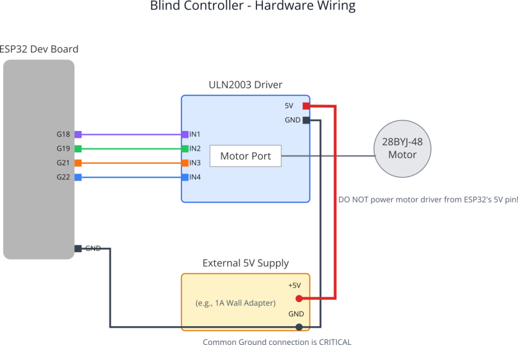
Wiring
Warning: The single most common failure in motor projects is an inadequate power supply. Do not power the ULN2003 driver board from the ESP32’s 5V pin. The motor’s current draw will cause the ESP32’s voltage to drop, leading to random resets (brownouts).
- Power Connections:
- Connect the
+and-terminals of your external 5V power supply to the power rails of your breadboard. - Connect the
5VandGNDpins of the ULN2003 driver board to the 5V and GND rails on the breadboard. - Connect a
GNDpin from the ESP32 to the GND rail on the breadboard. This common ground is essential for the logic signals to work.
- Connect the
- Logic Connections (ESP32 to ULN2003):
GPIO18->IN1GPIO19->IN2GPIO21->IN3GPIO22->IN4
- Motor Connection:
- Plug the 28BYJ-48 motor’s connector into the socket on the ULN2003 board.
Project Configuration
- Create a new ESP-IDF project.
- In
main/CMakeLists.txt, add the required components:# Inside idf_component_register(...)REQUIRESidf::nvs_flashidf::esp_wifiidf::esp_eventidf::esp_netifidf::esp_logidf::esp_http_serveridf::esp_timer - Run
idf.py menuconfig. - Navigate to
Example Connection Configurationand set your Wi-Fi SSID and Password.
Code Implementation
We’ll create a single main.c file containing the motor logic, web server, and main application task.
/* main/main.c */
#include <stdio.h>
#include <string.h>
#include "freertos/FreeRTOS.h"
#include "freertos/task.h"
#include "freertos/semphr.h"
#include "esp_log.h"
#include "esp_wifi.h"
#include "nvs_flash.h"
#include "esp_event.h"
#include "esp_netif.h"
#include "esp_http_server.h"
#include "driver/gpio.h"
#include "esp_timer.h"

static const char *TAG = "BLIND_CONTROLLER";

// --- Hardware Configuration ---
#define MOTOR_IN1_GPIO GPIO_NUM_18
#define MOTOR_IN2_GPIO GPIO_NUM_19
#define MOTOR_IN3_GPIO GPIO_NUM_21
#define MOTOR_IN4_GPIO GPIO_NUM_22

// --- Motor Logic Configuration ---
#define STEPS_PER_REVOLUTION 4096 // For 28BYJ-48 in half-step mode
#define TOTAL_TRAVEL_STEPS (STEPS_PER_REVOLUTION * 5) // Example: 5 full rotations for blinds
#define STEP_DELAY_US 1200 // Microseconds between steps. Controls speed.

typedef enum {
    STOPPED,
    MOVING_OPEN,
    MOVING_CLOSE
} motor_state_t;

// --- State Variables (protected by mutex) ---
static volatile motor_state_t current_motor_state = STOPPED;
static volatile int current_position_steps = 0;
static SemaphoreHandle_t state_mutex;
static esp_timer_handle_t motor_timer_handle;

// Half-step sequence (8 steps)
const int step_sequence[8][4] = {
    {1, 0, 0, 0}, {1, 1, 0, 0}, {0, 1, 0, 0}, {0, 1, 1, 0},
    {0, 0, 1, 0}, {0, 0, 1, 1}, {0, 0, 0, 1}, {0, 0, 0, 1}
};
static int current_step_index = 0;

// --- Function Prototypes ---
static void wifi_init(void);
static esp_err_t http_event_handler(httpd_req_t *req, httpd_err_code_t err);
static httpd_handle_t start_webserver(void);
static void configure_motor_gpio(void);
static void motor_timer_callback(void* arg);

// --- Motor Control Functions ---
void set_motor_step(int step) {
    gpio_set_level(MOTOR_IN1_GPIO, step_sequence[step][0]);
    gpio_set_level(MOTOR_IN2_GPIO, step_sequence[step][1]);
    gpio_set_level(MOTOR_IN3_GPIO, step_sequence[step][2]);
    gpio_set_level(MOTOR_IN4_GPIO, step_sequence[step][3]);
}

void stop_motor() {
    esp_timer_stop(motor_timer_handle);
    // De-energize coils to save power and reduce heat
    gpio_set_level(MOTOR_IN1_GPIO, 0);
    gpio_set_level(MOTOR_IN2_GPIO, 0);
    gpio_set_level(MOTOR_IN3_GPIO, 0);
    gpio_set_level(MOTOR_IN4_GPIO, 0);
}

static void motor_timer_callback(void* arg) {
    xSemaphoreTake(state_mutex, portMAX_DELAY);

    if (current_motor_state == MOVING_OPEN) {
        if (current_position_steps > 0) {
            current_step_index = (current_step_index - 1 + 8) % 8; // Move backwards
            set_motor_step(current_step_index);
            current_position_steps--;
        } else {
            current_motor_state = STOPPED;
        }
    } else if (current_motor_state == MOVING_CLOSE) {
        if (current_position_steps < TOTAL_TRAVEL_STEPS) {
            current_step_index = (current_step_index + 1) % 8; // Move forwards
            set_motor_step(current_step_index);
            current_position_steps++;
        } else {
            current_motor_state = STOPPED;
        }
    }

    if (current_motor_state == STOPPED) {
        stop_motor();
        ESP_LOGI(TAG, "Motor stopped at position: %d", current_position_steps);
    }

    xSemaphoreGive(state_mutex);
}

// --- Web Server Handlers ---
static esp_err_t root_get_handler(httpd_req_t *req) {
    char resp_str[512];
    snprintf(resp_str, sizeof(resp_str),
        "<html><body><h1>ESP32 Blind Control</h1>"
        "<p>Current Position: %d / %d</p>"
        "<button onclick=\"fetch('/open')\">Open</button>"
        "<button onclick=\"fetch('/close')\">Close</button>"
        "<button onclick=\"fetch('/stop')\">Stop</button>"
        "</body></html>",
        current_position_steps, TOTAL_TRAVEL_STEPS);

    httpd_resp_send(req, resp_str, HTTPD_RESP_USE_STRLEN);
    return ESP_OK;
}

static esp_err_t open_handler(httpd_req_t *req) {
    xSemaphoreTake(state_mutex, portMAX_DELAY);
    if(current_motor_state != MOVING_OPEN) {
        ESP_LOGI(TAG, "Command: OPEN");
        current_motor_state = MOVING_OPEN;
        esp_timer_start_periodic(motor_timer_handle, STEP_DELAY_US);
    }
    xSemaphoreGive(state_mutex);
    httpd_resp_send(req, "Opening...", HTTPD_RESP_USE_STRLEN);
    return ESP_OK;
}

static esp_err_t close_handler(httpd_req_t *req) {
    xSemaphoreTake(state_mutex, portMAX_DELAY);
    if(current_motor_state != MOVING_CLOSE) {
        ESP_LOGI(TAG, "Command: CLOSE");
        current_motor_state = MOVING_CLOSE;
        esp_timer_start_periodic(motor_timer_handle, STEP_DELAY_US);
    }
    xSemaphoreGive(state_mutex);
    httpd_resp_send(req, "Closing...", HTTPD_RESP_USE_STRLEN);
    return ESP_OK;
}

static esp_err_t stop_handler(httpd_req_t *req) {
    xSemaphoreTake(state_mutex, portMAX_DELAY);
    if(current_motor_state != STOPPED) {
        ESP_LOGI(TAG, "Command: STOP");
        current_motor_state = STOPPED;
        // The timer callback will handle the actual stopping
    }
    xSemaphoreGive(state_mutex);
    httpd_resp_send(req, "Stopping...", HTTPD_RESP_USE_STRLEN);
    return ESP_OK;
}

void app_main(void) {
    // Initialize NVS
    esp_err_t ret = nvs_flash_init();
    if (ret == ESP_ERR_NVS_NO_FREE_PAGES || ret == ESP_ERR_NVS_NEW_VERSION_FOUND) {
      ESP_ERROR_CHECK(nvs_flash_erase());
      ret = nvs_flash_init();
    }
    ESP_ERROR_CHECK(ret);

    state_mutex = xSemaphoreCreateMutex();
    configure_motor_gpio();

    // Create high-resolution timer
    const esp_timer_create_args_t motor_timer_args = {
            .callback = &motor_timer_callback,
            .name = "motor_step_timer"
    };
    ESP_ERROR_CHECK(esp_timer_create(&motor_timer_args, &motor_timer_handle));

    wifi_init();
    start_webserver();

    ESP_LOGI(TAG, "Initialization complete. Awaiting commands.");
}


// --- Initialization Functions (condensed for brevity) ---
static void configure_motor_gpio(void) {
    gpio_config_t io_conf = {
        .pin_bit_mask = (1ULL<<MOTOR_IN1_GPIO) | (1ULL<<MOTOR_IN2_GPIO) | (1ULL<<MOTOR_IN3_GPIO) | (1ULL<<MOTOR_IN4_GPIO),
        .mode = GPIO_MODE_OUTPUT,
        .intr_type = GPIO_INTR_DISABLE,
        .pull_down_en = 0,
        .pull_up_en = 0
    };
    gpio_config(&io_conf);
}

static httpd_uri_t root = { .uri = "/", .method = HTTP_GET, .handler = root_get_handler };
static httpd_uri_t open_uri = { .uri = "/open", .method = HTTP_GET, .handler = open_handler };
static httpd_uri_t close_uri = { .uri = "/close", .method = HTTP_GET, .handler = close_handler };
static httpd_uri_t stop_uri = { .uri = "/stop", .method = HTTP_GET, .handler = stop_handler };

static httpd_handle_t start_webserver(void) {
    httpd_handle_t server = NULL;
    httpd_config_t config = HTTPD_DEFAULT_CONFIG();
    config.lru_purge_enable = true;

    if (httpd_start(&server, &config) == ESP_OK) {
        httpd_register_uri_handler(server, &root);
        httpd_register_uri_handler(server, &open_uri);
        httpd_register_uri_handler(server, &close_uri);
        httpd_register_uri_handler(server, &stop_uri);
        return server;
    }
    return NULL;
}

static void wifi_event_handler(void* arg, esp_event_base_t event_base, int32_t event_id, void* event_data) {
    if (event_id == WIFI_EVENT_STA_START) {
        esp_wifi_connect();
    } else if (event_id == IP_EVENT_STA_GOT_IP) {
        ip_event_got_ip_t* event = (ip_event_got_ip_t*) event_data;
        ESP_LOGI(TAG, "Got IP address: " IPSTR, IP2STR(&event->ip_info.ip));
    }
}

static void wifi_init(void) {
    ESP_ERROR_CHECK(esp_netif_init());
    ESP_ERROR_CHECK(esp_event_loop_create_default());
    esp_netif_create_default_wifi_sta();
    wifi_init_config_t cfg = WIFI_INIT_CONFIG_DEFAULT();
    ESP_ERROR_CHECK(esp_wifi_init(&cfg));
    esp_event_handler_instance_t instance_any_id;
    esp_event_handler_instance_t instance_got_ip;
    ESP_ERROR_CHECK(esp_event_handler_instance_register(WIFI_EVENT, ESP_EVENT_ANY_ID, &wifi_event_handler, NULL, &instance_any_id));
    ESP_ERROR_CHECK(esp_event_handler_instance_register(IP_EVENT, IP_EVENT_STA_GOT_IP, &wifi_event_handler, NULL, &instance_got_ip));
    wifi_config_t wifi_config = {
        .sta = { .ssid = CONFIG_ESP_WIFI_SSID, .password = CONFIG_ESP_WIFI_PASSWORD },
    };
    ESP_ERROR_CHECK(esp_wifi_set_mode(WIFI_MODE_STA));
    ESP_ERROR_CHECK(esp_wifi_set_config(WIFI_IF_STA, &wifi_config));
    ESP_ERROR_CHECK(esp_wifi_start());
}
sequenceDiagram
    participant B as Browser
    participant E as ESP32 HTTP Server
    participant T as Motor Timer (esp_timer)

    B->>E: GET /close

    activate E
    E-->>T: Update state to MOVING_CLOSE
    E-->>T: esp_timer_start_periodic()
    E-->>B: HTTP 200 OK ("Closing...")
    deactivate E

    loop Motor is Moving
        T-->>T: timer_callback()
        Note over T: Check state is MOVING_CLOSE
        Note over T: Increment step count
        Note over T: Set GPIOs for next step
    end

    alt Position Limit Reached
        T-->>T: timer_callback()
        Note over T: current_position >= TOTAL_STEPS
        T-->>T: Update state to STOPPED
        T-->>T: esp_timer_stop()
    end
Build and Flash
- Connect your ESP32, ensuring the motor has its separate 5V supply.
- Use the VS Code ESP-IDF extension to select the COM port, then build, flash, and monitor.
- Watch the serial monitor. Once the ESP32 connects to Wi-Fi, it will print its IP address.
Observe the Output
- Open a web browser on a device connected to the same Wi-Fi network.
- Navigate to the IP address shown in the serial monitor (e.g.,
http://192.168.1.105). - You should see the control page. Click “Close” to start the motor. You’ll hear it turning and see the position count increase in the logs. Click “Stop” or “Open,” and observe the motor’s response. The motor will automatically stop when it reaches the
TOTAL_TRAVEL_STEPSlimit.
Variant Notes
- Power Stability: This is the most important variant-agnostic point. Smaller ESP32 modules, especially the C-series and H-series, are more sensitive to power supply fluctuations. The rule is universal: Always power your motors from a separate, dedicated power supply.
- GPIO Pins: The GPIOs used in this example (
18,19,21,22) are generally safe on most ESP32, S2, and S3 boards. On smaller boards like the ESP32-C3, you have fewer pins, so you must choose them carefully from the datasheet, avoiding pins used for strapping or other critical functions. - Performance: For this slow-moving application, driving the motor with GPIOs toggled by an
esp_timeris perfectly adequate for all variants. For applications requiring very high speeds or simultaneous control of multiple stepper motors, you could offload the pulse generation to hardware peripherals like the RMT (Remote Control) or MCPWM (Motor Control PWM) modules, which are available on most variants. This would free up the CPU for other tasks. - Wireless Protocols: This example uses Wi-Fi. It will work on the ESP32, S2, S3, C3, and C6. The ESP32-H2 lacks Wi-Fi but has IEEE 802.15.4 (Zigbee/Thread) and BLE. To adapt this project for an H2, the
esp_http_serverwould be replaced with a communication stack appropriate for those protocols, for instance, a BLE GATT server that exposes characteristics for “open,” “close,” and “position.”
Common Mistakes & Troubleshooting Tips
| Mistake / Issue | Symptom(s) | Troubleshooting / Solution |
|---|---|---|
| ESP32 constantly resets (brownout). | The device reboots as soon as the motor is commanded to move. The serial monitor shows a “Brownout detector was triggered” error. |
Use a Separate Power Supply: This is the most common issue. The motor’s current draw causes the ESP32’s voltage to dip.
|
| Motor buzzes/vibrates but won’t turn. | The motor makes noise and may twitch slightly but does not rotate smoothly. |
Check Wiring and Sequence: 1. Wiring: Carefully verify the connections from ESP32 GPIOs to the ULN2003’s IN1, IN2, IN3, and IN4 pins. An incorrect order will break the sequence. 2. Code Sequence: Double-check that the step_sequence array in your code is correct. A single incorrect value will disrupt the magnetic field rotation.
|
| Motor is weak or skips steps. | The motor tries to turn but seems to struggle, get stuck, or move erratically. |
Slow Down the Motor: The motor is being driven too fast. Increase the delay between steps. In the code, increase the value of STEP_DELAY_US (e.g., from 1200 to 1800 or 2000). Also, ensure your 5V power supply can provide sufficient current (at least 500mA).
|
| Motor turns in the wrong direction. | Clicking “Open” closes the blinds, and “Close” opens them. |
Invert the Step Logic: In the motor_timer_callback function, swap the logic for moving forwards and backwards. Change the MOVING_OPEN block to increment the step index (current_step_index++) and the MOVING_CLOSE block to decrement it (current_step_index--).
|
Exercises
- Implement Physical Limit Switches:
- Wire two push buttons to two free GPIO pins, configured as inputs with internal pull-ups. These will be your “fully open” and “fully closed” limit switches.
- Create a “homing” function that runs on startup. It should move the motor towards the “closed” direction until the closed limit switch is pressed. At this point, set
current_position_stepstoTOTAL_TRAVEL_STEPS. - Modify the
motor_timer_callbackto stop the motor immediately if the appropriate limit switch is pressed, regardless of the step count. This makes the system far more robust.
- Add Positional Control:
- Change the web interface. Replace the buttons with an HTML slider (
<input type="range" min="0" max="100">) and a “Go” button. - Write JavaScript to send the slider’s value to a new endpoint, e.g.,
/setpos?percent=50. - In your C code, add a handler for
/setpos. It should parse the percentage value, calculate the target step count (target_steps = (percent / 100.0) * TOTAL_TRAVEL_STEPS), and then move the motor to that position.
- Change the web interface. Replace the buttons with an HTML slider (
- Scheduled Operation with Time Sync:
- Integrate the SNTP client from Chapter 98 to synchronize the ESP32’s internal clock with a time server.
- Create a new FreeRTOS task that wakes up once per minute.
- In this new task, check the current time. If it’s a specific time (e.g., 7:00 AM), command the blinds to open. If it’s another time (e.g., 8:00 PM), command them to close. This adds true automation to your project.
Summary
- Stepper motors provide precise, step-by-step positional control, making them excellent for automated systems like blind controllers.
- A motor driver (like the ULN2003) is mandatory to safely interface a motor with a low-power microcontroller like the ESP32.
- Stable motor operation relies on a separate and adequate power supply to prevent system resets and ensure sufficient torque.
- The ESP-IDF
esp_timerprovides the high-resolution, periodic callbacks needed for generating clean, consistently timed step pulses. - The
esp_http_servercomponent allows you to quickly build a web-based user interface for remote control over Wi-Fi. - Combining state management (using enums and mutexes) with hardware control (timers and GPIO) is a fundamental pattern in embedded systems programming.
Further Reading
- ESP-IDF
esp_timerDocumentation: High Resolution Timer API Reference - ESP-IDF
esp_http_serverDocumentation: HTTP Server API Reference - 42bots: In-depth 28BYJ-48 Tutorial: Controlling 28BYJ-48 Stepper Motor with ULN2003 Driver (The principles and wiring are the same, even though the example uses Arduino).
