
Chapter 190: AS-Interface (AS-i) Implementation
Chapter Objectives
By the end of this chapter, you will be able to:
- Understand the fundamentals of AS-Interface (AS-i) as a sensor/actuator bus.
- Describe the unique characteristics of AS-i, including its two-wire cable for data and power.
- Explain the AS-i master-slave communication principle, including cyclic polling and addressing.
- Understand the basics of AS-i data exchange and telegram structure.
- Recognize the role of AS-i specific components like AS-i masters, power supplies, and slaves.
- Identify the critical need for dedicated AS-i ASICs or specialized controllers for implementing AS-i nodes.
- Discuss conceptual approaches for an ESP32 to interface with an AS-i controller IC to act as part of an AS-i device.
- Appreciate the differences among ESP32 variants concerning their suitability as host controllers for AS-i ICs.
- Be aware of common challenges in developing AS-i enabled devices.
Introduction
In the hierarchy of industrial automation networks, AS-Interface (Actuator Sensor Interface, commonly abbreviated as AS-i) occupies a unique position at the lowest level. It is designed as a simple, cost-effective, and efficient networking solution to connect binary (ON/OFF) sensors and actuators, as well as simple analog devices, to higher-level control systems. AS-i serves as a direct replacement for traditional parallel wiring, significantly reducing cabling complexity, installation time, and costs.
Unlike more complex fieldbuses or Industrial Ethernet protocols, AS-i focuses on simplicity and speed for a limited amount of data per device. Its most distinctive feature is the use of a single, unshielded, two-conductor flat yellow cable that carries both data and power for the connected slaves.
While an ESP32 cannot natively implement the AS-i physical layer or protocol using its standard peripherals (like UART, SPI, or TWAI), it can serve as a host microcontroller for a dedicated AS-i slave (or master) ASIC or a specialized module. This chapter will introduce the core concepts of AS-Interface and explore the conceptual integration of an ESP32 with such dedicated AS-i hardware, enabling the ESP32 to manage application logic for an AS-i connected device.
Theory
AS-Interface Overview
AS-Interface is an open standard (IEC 62026-2) designed for networking simple field devices in automation systems. It was developed to simplify the connection of binary sensors and actuators.
Key Characteristics:
- Simplicity: Easy to install, configure, and maintain.
- Cost-Effective: Reduces wiring costs significantly compared to parallel wiring.
- Two-Wire Bus: A single, unshielded, two-conductor flat (or round) cable carries both data and 24V DC power for many slave devices. The cable is often yellow for standard AS-i and black for auxiliary power AS-i.
- Master-Slave Architecture: A single AS-i master controls communication on the bus, cyclically polling connected slave devices.
- Fast Cycle Times: Typically around 5 ms for up to 31 standard slaves (or 10 ms for 62 extended address slaves), ensuring rapid updates for simple I/O.
- Flexible Topology: Supports line, star, tree, or mesh topologies.
- Insulation Displacement Connectors (IDCs): Allows for quick and easy connection of slaves to the flat cable without cutting or stripping wires.
AS-i Physical Layer
- Cabling:
- Yellow Cable: Standard AS-i cable, two conductors, typically flat and unshielded. Carries data and 24V DC power (up to 8A total for the segment).
- Black Cable: Used for AS-i networks requiring auxiliary power (e.g., for actuators with higher power demand). Data is still on the AS-i lines, but power is supplied separately via the black cable.
- The cable is designed to be self-healing from punctures made by IDC connectors.
- Data and Power Transmission:
- Data is modulated onto the 24V DC power supply voltage using Manchester II encoding.
- The AS-i master provides the power and the data clock.
- AS-i Power Supply: A specialized power supply unit is required for AS-i. It provides the 24V DC, decouples data from the power line for the master, and often includes earth fault monitoring.
- No Termination Resistors: Unlike CAN, AS-i does not require termination resistors at the bus ends. The network length is limited (typically 100m, extendable with repeaters up to 300m or more with specific network configurations).

AS-i Data Link Layer
- Master-Slave Polling:
- The AS-i master cyclically polls each configured slave device by sending a master call (telegram).
- The addressed slave responds with a slave response (telegram).
- Telegram Structure:
- Master Call: Contains Start Bit (SB), Control Bits (CB – indicating master or slave telegram), Slave Address (A0-A4), Information Bits (I0-I3 – typically outputs for the slave or parameter/command data), Parity Bit (PB), End Bit (EB).
- Slave Response: Contains SB, CB, Information Bits (I0-I3 – typically inputs from the slave or status data), Parity Bit (PB), End Bit (EB).
- Data transmission is typically 4 bits per slave per cycle in each direction.
- Manchester II Encoding: Ensures frequent signal transitions for clock recovery by the slaves and DC-free transmission.
- Addressing:
- Standard Addressing (AS-i Specification up to v2.0): Slaves have addresses from 0 to 31. Address 0 is often used for new/unconfigured slaves.
- Extended Addressing (A/B Addressing, AS-i Specification v2.1 and later): Allows up to 62 slaves (1A to 31A and 1B to 31B). Each physical address (1-31) can have two sub-addresses (A and B). This is achieved by the master polling A-slaves and B-slaves in alternate cycles or using specific command sequences.
- Slaves are typically assigned addresses by the master during commissioning or using a handheld addressing tool.
%%{ init: { 'theme': 'base', 'themeVariables': { 'fontFamily': 'Open Sans, sans-serif' } } }%%
graph TD
    subgraph AS-i Communication Cycle
        Master_Call(Master Call Telegram - 14 bits)
        Slave_Response(Slave Response Telegram - 7 bits)

        Master_Call -->|"Master polls one slave"| Pause1(Pause)
        Pause1 --> Slave_Response
        Slave_Response -->|"Slave responds"| Pause2(Pause)
        Pause2 -->|"Cycle repeats for next slave"| Master_Call
    end

    subgraph "Master Call Breakdown"
        direction TB
        SB1(SB) --- CB1(CB) --- A(A0-A4) --- I1(I0-I3) --- PB1(PB) --- EB1(EB)
    end

    subgraph "Slave Response Breakdown"
        direction TB
        SB2(SB) --- CB2(CB) --- I2(I0-I3) --- PB2(PB) --- EB2(EB)
    end

    subgraph "Field Descriptions"
        direction LR
        SB("<b>SB</b><br>Start Bit")
        CB("<b>CB</b><br>Control Bit")
        Addr("<b>A0-A4</b><br>Slave Address<br>(5 bits)")
        Info("<b>I0-I3</b><br>Information Bits<br>(4 bits of data)")
        PB("<b>PB</b><br>Parity Bit")
        EB("<b>EB</b><br>End Bit")
    end

    %% Styling
    style Master_Call fill:#EDE9FE,stroke:#5B21B6,stroke-width:2px,color:#5B21B6
    style Slave_Response fill:#DBEAFE,stroke:#2563EB,stroke-width:2px,color:#1E40AF
    style Pause1 fill:#F3F4F6,stroke:#6B7280
    style Pause2 fill:#F3F4F6,stroke:#6B7280

    style SB1 fill:#D1FAE5,stroke:#059669
    style CB1 fill:#D1FAE5,stroke:#059669
    style A fill:#FEF3C7,stroke:#D97706
    style I1 fill:#FEE2E2,stroke:#DC2626
    style PB1 fill:#D1FAE5,stroke:#059669
    style EB1 fill:#D1FAE5,stroke:#059669

    style SB2 fill:#D1FAE5,stroke:#059669
    style CB2 fill:#D1FAE5,stroke:#059669
    style I2 fill:#FEE2E2,stroke:#DC2626
    style PB2 fill:#D1FAE5,stroke:#059669
    style EB2 fill:#D1FAE5,stroke:#059669
AS-i Communication Cycle
- Master Call: The master sends a request to a specific slave address. This call includes 4 bits of output data for that slave.
- Pause 1: A short pause.
- Slave Response: The addressed slave responds with its 4 bits of input data.
- Pause 2: Another short pause.
- The master then polls the next slave address.
This sequence repeats for all configured slaves. Additionally, the master periodically sends management calls for diagnostics, parameter setting, and configuration.
AS-i Device Types
- AS-i Master: Controls the entire AS-i network segment. It interfaces with a higher-level controller (e.g., PLC, PC) via a fieldbus gateway (e.g., PROFIBUS, PROFINET, EtherNet/IP to AS-i gateway) or can be a PLC module itself.
- AS-i Slave: A sensor, actuator, or I/O module connected to the AS-i bus.
- Standard Slaves: Exchange 4 bits of input and 4 bits of output data per cycle.
- Analog Slaves: Use multiple cycles or specific profiles to transmit analog values (e.g., 12-bit or 16-bit values are transmitted over several cycles using 4-bit nibbles).
- Safety Slaves (ASIsafe): Special slaves used in safety-related applications, part of the ASIsafe protocol, which transmits safety data over the standard AS-i network.
- AS-i Power Supply: Provides the specialized 24V DC power with data decoupling.
- AS-i Repeater/Extender: Used to extend the network length or create galvanically isolated segments.
- AS-i Tuner/Addressing Device: Handheld device for setting slave addresses and diagnosing the network.
AS-i Profiles
To ensure interoperability for more complex slaves (especially analog slaves), AS-i defines profiles. A profile specifies the interpretation of the 4 data bits (I/O bits) and parameter bits. For example, an analog input profile might define how a 12-bit analog value is transmitted over three AS-i cycles.
The Need for Dedicated AS-i Hardware (ASICs)
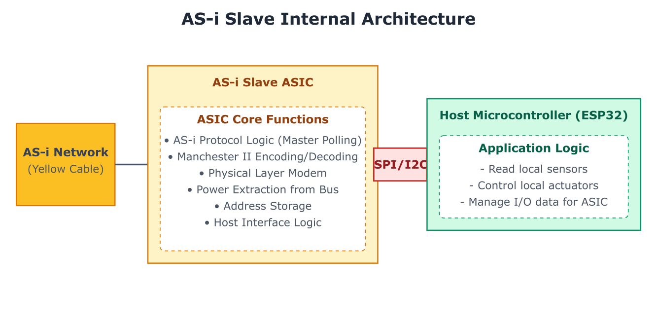
The unique physical layer (data and power on two wires, Manchester II encoding superimposed on DC) and the strict timing of the AS-i protocol mean that standard microcontroller peripherals (like UART, SPI, I2C, or even CAN controllers) cannot directly implement an AS-i interface.
- AS-i Slave ASIC/IC: Almost all AS-i slave devices contain a dedicated AS-i slave chip. This chip handles:
- Physical layer interface (modem functionality for Manchester II encoding/decoding).
- Power extraction from the AS-i line (for low-power slaves).
- AS-i protocol handling (telegram recognition, address matching, timing, response generation).
- Data exchange with a host microcontroller (e.g., via SPI, I2C, parallel I/O, or simple digital lines for binary slaves).
- Storing the slave’s address.
- AS-i Master ASIC/IC: Similarly, AS-i masters also use specialized ASICs or FPGA implementations to manage the bus, generate polling cycles, and interface with the higher-level control system.
Therefore, if an ESP32 is to be part of an AS-i slave device, it will act as the application host controller, communicating with a dedicated AS-i slave ASIC. The ESP32 would read sensor data or manage application logic and then pass the 4 bits of I/O data to/from the AS-i slave ASIC.
Practical Examples
This section will conceptually outline how an ESP32 might interface with a hypothetical AS-i slave ASIC via an SPI interface. The focus is on the interaction between the ESP32 and the ASIC, not on implementing the AS-i protocol itself on the ESP32.
Hardware Setup
- ESP32 Development Board.
- Hypothetical AS-i Slave ASIC Module: A module featuring an AS-i slave ASIC (e.g., based on chips like NXP A2SI, Infineon ASI4U, or similar, though specific chip details vary) that provides an SPI interface for a host microcontroller. This module would also have connections for the AS-i yellow cable.
- Connections (ESP32 to AS-i Slave ASIC via SPI):
- ESP32 SPI MOSI -> ASIC SPI MOSI
- ESP32 SPI MISO <- ASIC SPI MISO
- ESP32 SPI SCLK -> ASIC SPI SCLK
- ESP32 GPIO (CS) -> ASIC SPI Chip Select
- ESP32 GPIO (IRQ/DataReady) <- ASIC Interrupt/Data Ready Output (optional, depends on ASIC)
- Power and Ground connections.
- AS-i Master and Power Supply: A functioning AS-i network segment with a master and power supply.
- AS-i Cable.
Software: ESP32 Interfacing with an AS-i Slave ASIC (Conceptual)
We assume the AS-i slave ASIC handles all low-level AS-i communication. The ESP32’s role is to:
- Configure the ASIC (if necessary, e.g., setting operational modes).
- Periodically read input data (4 bits) received by the ASIC from the AS-i master.
- Periodically write output data (4 bits) to the ASIC to be sent to the AS-i master.
- Handle any parameter exchange if the ASIC supports it via the host interface.
Project Setup in VS Code
- Create a new ESP-IDF v5.x project (e.g.,
esp32_asi_slave_host). - No specific “AS-i stack” is typically run on the ESP32 for this setup, as the ASIC is the AS-i stack. The ESP32 code is an application driver for the ASIC.
Main Application Code (main/main.c)
This code focuses on initializing SPI for ASIC communication and simulating the periodic exchange of I/O data with the hypothetical AS-i slave ASIC.
#include <stdio.h>
#include <string.h>
#include "freertos/FreeRTOS.h"
#include "freertos/task.h"
#include "esp_system.h"
#include "esp_log.h"
#include "driver/spi_master.h"
#include "driver/gpio.h"
static const char *TAG = "ASI_APP_HOST";
// SPI Configuration for AS-i Slave ASIC (Example for VSPI bus)
#define ASI_ASIC_SPI_HOST SPI3_HOST
#define PIN_NUM_MOSI GPIO_NUM_23
#define PIN_NUM_MISO GPIO_NUM_19
#define PIN_NUM_CLK GPIO_NUM_18
#define PIN_NUM_CS GPIO_NUM_5
#define PIN_NUM_ASIC_IRQ GPIO_NUM_4 // Optional: ASIC interrupt/data ready
spi_device_handle_t g_asi_asic_spi_handle;
// Application data (representing the 4-bit I/O of a simple AS-i slave)
// The ESP32 application will read its sensor inputs into app_input_nibble
// and set app_output_nibble based on its logic or data from another interface.
uint8_t app_input_nibble = 0x0; // 4 bits (0-15) from sensors to AS-i master
uint8_t app_output_nibble = 0x0; // 4 bits (0-15) from AS-i master to actuators
// --- Hypothetical AS-i ASIC SPI Communication Functions ---
/**
* @brief Reads data from the AS-i ASIC (e.g., input nibble, status).
* This is highly dependent on the specific ASIC's SPI protocol.
*
* @param reg_addr Register or command to read.
* @param data Pointer to store read data.
* @param len Length of data to read.
* @return esp_err_t ESP_OK on success.
*/
esp_err_t asi_asic_read_spi(uint8_t reg_addr, uint8_t *data, size_t len) {
if (len == 0) return ESP_OK;
// Actual implementation depends on ASIC:
// May involve sending a command byte (reg_addr | READ_BIT), then clocking in data.
spi_transaction_t t;
memset(&t, 0, sizeof(t));
t.flags = 0; // Potentially SPI_TRANS_USE_TXDATA if sending command in tx_data
t.cmd = reg_addr; // Example: command/address phase
t.addr = 0; // No address phase or incorporated in cmd
t.length = 0; // Length of data to send (command only)
t.rxlength = len * 8; // Length of data to receive in bits
t.tx_buffer = NULL;
t.rx_buffer = data;
// For a common scenario: send command/address, then read data
// uint8_t tx_cmd[1] = {reg_addr | 0x80}; // Example: MSB set for read
// memset(&t, 0, sizeof(t));
// t.length = 8; // Command length
// t.tx_buffer = tx_cmd;
// t.rxlength = len * 8;
// t.rx_buffer = data;
// This is a placeholder for actual ASIC SPI read logic
ESP_LOGD(TAG, "Conceptual ASIC SPI Read: Reg 0x%02X, Len %d", reg_addr, len);
// Simulate reading: for input nibble, let's assume reg_addr 0x01 reads it
if (reg_addr == 0x01 && data && len > 0) {
*data = app_input_nibble & 0x0F; // Simulate ASIC providing the app's input
}
return ESP_OK; // Placeholder
}
/**
* @brief Writes data to the AS-i ASIC (e.g., output nibble, configuration).
* This is highly dependent on the specific ASIC's SPI protocol.
*
* @param reg_addr Register or command to write.
* @param data Pointer to data to write.
* @param len Length of data to write.
* @return esp_err_t ESP_OK on success.
*/
esp_err_t asi_asic_write_spi(uint8_t reg_addr, const uint8_t *data, size_t len) {
if (len == 0) return ESP_OK;
// Actual implementation depends on ASIC:
// May involve sending a command byte (reg_addr & ~READ_BIT), then data.
spi_transaction_t t;
memset(&t, 0, sizeof(t));
// Example: command/address phase followed by data phase
// uint8_t tx_payload[1 + len];
// tx_payload[0] = reg_addr; // Example: command/address
// memcpy(&tx_payload[1], data, len);
// t.length = (1 + len) * 8;
// t.tx_buffer = tx_payload;
// t.rxlength = 0;
// t.rx_buffer = NULL;
// This is a placeholder for actual ASIC SPI write logic
ESP_LOGD(TAG, "Conceptual ASIC SPI Write: Reg 0x%02X, Data 0x%02X, Len %d", reg_addr, (data ? *data : 0), len);
// Simulate writing: for output nibble, let's assume reg_addr 0x02 takes it
if (reg_addr == 0x02 && data && len > 0) {
app_output_nibble = (*data) & 0x0F; // Simulate ESP32 providing output to ASIC
// The ASIC would then make this available to AS-i master
ESP_LOGI(TAG, "App sets output nibble for ASIC: 0x%X", app_output_nibble);
}
return ESP_OK; // Placeholder
}
// --- End of Hypothetical ASIC SPI Functions ---
static void initialize_asic_spi_interface(void) {
spi_bus_config_t buscfg = {
.mosi_io_num = PIN_NUM_MOSI,
.miso_io_num = PIN_NUM_MISO,
.sclk_io_num = PIN_NUM_CLK,
.quadwp_io_num = -1,
.quadhd_io_num = -1,
.max_transfer_sz = 32 // AS-i data exchanges are small
};
spi_device_interface_config_t devcfg = {
.clock_speed_hz = 1 * 1000 * 1000, // Clock out at 1 MHz (ASIC dependent, often lower for AS-i ASICs)
.mode = 0, // SPI mode 0 (CPOL=0, CPHA=0) - verify with ASIC datasheet
.spics_io_num = PIN_NUM_CS,
.queue_size = 3
};
esp_err_t ret = spi_bus_initialize(ASI_ASIC_SPI_HOST, &buscfg, SPI_DMA_CH_AUTO);
ESP_ERROR_CHECK(ret);
ret = spi_bus_add_device(ASI_ASIC_SPI_HOST, &devcfg, &g_asi_asic_spi_handle);
ESP_ERROR_CHECK(ret);
ESP_LOGI(TAG, "AS-i ASIC SPI Initialized.");
// Configure ASIC IRQ pin if used
if (PIN_NUM_ASIC_IRQ != -1) {
gpio_config_t io_conf = {
.intr_type = GPIO_INTR_POSEDGE, // Or as specified by ASIC
.pin_bit_mask = (1ULL << PIN_NUM_ASIC_IRQ),
.mode = GPIO_MODE_INPUT,
.pull_up_en = GPIO_PULLUP_DISABLE, // Or as required
};
gpio_config(&io_conf);
// ISR setup would go here if using interrupts from ASIC
ESP_LOGI(TAG, "AS-i ASIC IRQ Pin %d configured (conceptual).", PIN_NUM_ASIC_IRQ);
}
}
void asi_host_application_task(void *pvParameters) {
ESP_LOGI(TAG, "AS-i Host Application Task Started.");
// Initialize application I/O data (example)
app_input_nibble = 0x0A; // e.g., binary sensors 1010
app_output_nibble = 0x00; // Outputs initially off
// In a real system, the AS-i ASIC is continuously polled by the AS-i master.
// The ESP32 needs to update/read data from the ASIC's shared memory/registers
// at a rate appropriate for the application and AS-i cycle.
// This might be synchronized with AS-i ASIC interrupts (e.g., "new data available" or "data consumed").
uint8_t current_asic_inputs = 0; // Data read from ASIC (master's outputs to this slave)
uint8_t data_to_asic_outputs = 0; // Data from ESP32 app to ASIC (slave's inputs to master)
while (1) {
// 1. Prepare data to be sent to AS-i master (slave inputs)
// This data comes from the ESP32 application's logic/sensors
data_to_asic_outputs = app_input_nibble & 0x0F;
// Write this data to the AS-i ASIC's output buffer/register via SPI
// The ASIC will then provide this data when polled by the AS-i master.
// Using conceptual register addresses: 0x01 for slave inputs (ESP32 writes to ASIC)
asi_asic_write_spi(0x01, &data_to_asic_outputs, 1); // Conceptual: ESP32 tells ASIC its inputs
// 2. Read data received from AS-i master (slave outputs)
// This data is in the AS-i ASIC's input buffer/register, placed there by the ASIC
// after an AS-i master call.
// Using conceptual register addresses: 0x02 for slave outputs (ESP32 reads from ASIC)
asi_asic_read_spi(0x02, ¤t_asic_inputs, 1); // Conceptual: ESP32 reads what master sent
app_output_nibble = current_asic_inputs & 0x0F;
// Application logic:
// - Update app_input_nibble based on local sensors connected to ESP32.
// - Act on app_output_nibble to control local actuators connected to ESP32.
ESP_LOGI(TAG, "AS-i Cycle Sim: Inputs to Master (via ASIC): 0x%X, Outputs from Master (via ASIC): 0x%X",
data_to_asic_outputs, app_output_nibble);
// Example: Toggle one bit of the input nibble for demonstration
static uint8_t sensor_val = 0;
sensor_val = !sensor_val;
if (sensor_val) {
app_input_nibble |= 0x01;
} else {
app_input_nibble &= ~0x01;
}
// Example: If master sends 0x05, turn on an ESP32-controlled LED
if (app_output_nibble == 0x05) {
// esp_rom_gpio_set_level(SOME_LED_GPIO, 1);
} else {
// esp_rom_gpio_set_level(SOME_LED_GPIO, 0);
}
vTaskDelay(pdMS_TO_TICKS(100)); // ESP32 application polls/updates ASIC data periodically
// This rate is not the AS-i bus cycle rate, but the app's update rate.
// The AS-i bus cycle is much faster (5-10ms) and handled by the ASIC.
}
}
void app_main(void) {
initialize_asic_spi_interface();
xTaskCreate(asi_host_application_task, "asi_host_task", 4096, NULL, 5, NULL);
}
main/CMakeLists.txt
idf_component_register(SRCS "main.c"
                       INCLUDE_DIRS ".")
Build Instructions
- Save
main.candCMakeLists.txtin themaindirectory. - Configure SPI pins in
main.cto match your ESP32-ASIC connections. - Build the project (
ESP-IDF: Build your project).
Run/Flash/Observe Steps
- Flash the firmware to your ESP32 board.
- Connect the ESP32-ASIC module to an active AS-i network (master, power supply).
- The AS-i master should be configured to communicate with the AS-i slave address programmed into your ASIC (addressing is usually done via an AS-i master or handheld tool directly to the ASIC, not via the ESP32).
- Open the ESP-IDF Monitor tool (
ESP-IDF: Monitor your device) to observe log messages from the ESP32. - Using the AS-i master’s diagnostic tools or programming interface:
- Observe the input data bits reported by the slave (which originate from
app_input_nibbleon the ESP32). - Try to change the output data bits for the slave from the master.
- Verify that
app_output_nibbleon the ESP32 reflects these changes, and the ESP32 application reacts accordingly.
- Observe the input data bits reported by the slave (which originate from
Tip: Debugging AS-i often involves an AS-i analyzer or the diagnostic features of the AS-i master to see the raw data being exchanged on the bus and the status of slaves.
Variant Notes
The ESP32’s role as a host controller for an AS-i slave ASIC is generally not demanding in terms of raw processing power for basic I/O.
- ESP32 (Original), ESP32-S2, ESP32-S3, ESP32-C3, ESP32-C6, ESP32-H2:
- All variants are capable of providing the SPI (or I2C, if the ASIC supports it) interface needed to communicate with an AS-i slave ASIC.
- CPU Performance: For simple binary I/O (4 bits in/out), the CPU load on the ESP32 will be minimal. Even the smaller C-series and H-series are more than adequate. If the ESP32 needs to perform complex application logic based on the AS-i data or manage more sophisticated AS-i profiles (like analog data handling over multiple cycles), then variants with more processing power (ESP32, ESP32-S3) might be preferred.
- Memory (RAM/Flash): The memory footprint for just relaying 4-bit I/O data is tiny. The ESP32’s application logic will be the primary consumer of memory. All variants should be sufficient for typical AS-i slave host applications.
- Peripherals: A free SPI interface is the main requirement.
General Considerations:
- AS-i ASIC Choice: The choice of AS-i slave ASIC is more critical than the ESP32 variant. The ASIC dictates the AS-i capabilities, power consumption from the bus, and the host interface (SPI, I2C, parallel).
- Simplicity of AS-i: Because AS-i is designed for simple devices, the demands on the host ESP32 are often low, allowing the ESP32 to handle other tasks simultaneously (e.g., Wi-Fi/Bluetooth communication for diagnostics or configuration, managing a local display).
Common Mistakes & Troubleshooting Tips
| Mistake / Issue | Symptom(s) | Troubleshooting / Solution |
|---|---|---|
| Direct Bus Connection | Attempting to connect ESP32 GPIOs directly to the yellow AS-i cable. This can damage the ESP32. | This will never work. You must use a dedicated AS-i slave ASIC between the ESP32 and the AS-i bus. |
| Incorrect Slave Addressing | Slave does not respond. Master reports “missing slave” or “configuration error”. Duplicate address causes network faults. | The ESP32 does not set the AS-i address. Use an AS-i master or handheld addressing tool to set a unique address (0-31 or A/B) on the slave ASIC itself. |
| ASIC Interface Errors (SPI/I2C) | ESP32 cannot communicate with the AS-i ASIC. I/O data read from ASIC is always zero or incorrect. | Use a logic analyzer to inspect the SPI/I2C bus. Verify wiring, SPI mode, and clock speed. Meticulously read the ASIC datasheet to understand its register map and access protocol. |
| AS-i Power Supply Issue | The entire network segment is down. No slaves are detected. Intermittent faults. | AS-i requires a special power supply with data decoupling. Verify the power supply is an “AS-i Power Supply” and is functioning correctly. Check for cable shorts or ground faults. |
| I/O Data Mapping Error | The slave is online, but sensor states are not reported correctly, or actuators don’t respond as expected. | This is an application logic issue on the ESP32. Debug the mapping between your application’s variables and the 4-bit I/O nibbles exchanged with the ASIC. Ensure bits are not flipped or misinterpreted. |
Exercises
- Exercise 1: AS-i Slave ASIC Datasheet Review
- Search online for a datasheet of a common AS-i slave ASIC (e.g., NXP A2SI series, Infineon ASI4U, or similar).
- Identify:
- The type of host microcontroller interface it provides (e.g., SPI, I2C, parallel).
- How the 4-bit input data (DI0-DI3) and 4-bit output data (DO0-DO3) are accessed by the host microcontroller.
- How the AS-i address is typically set for the ASIC.
- Does it support extended addressing (A/B slaves)?
- Exercise 2: Conceptual Data Mapping
- Imagine your ESP32 is connected to an AS-i slave ASIC. The ESP32 has two digital sensors (SensorA, SensorB) connected to its GPIOs and needs to control two LEDs (LED_X, LED_Y) via its GPIOs.
- Describe how you would map these four signals to the 4-bit input nibble (DI) and 4-bit output nibble (DO) that the ESP32 exchanges with the AS-i slave ASIC. For example:
- DI0 = SensorA state
- DI1 = SensorB state
- DO0 controls LED_X
- DO1 controls LED_Y
- What would the ESP32 application code (pseudo-code) look like to read sensor states and update
app_input_nibble, and to readapp_output_nibbleand control the LEDs?
- Exercise 3: AS-i Network Components Identification
- Research and list the essential components required to build a minimal functional AS-i network segment.
- For each component, briefly describe its role in the network (e.g., AS-i Master, AS-i Power Supply, AS-i Slave, AS-i Cable).
Summary
- AS-Interface (AS-i) is a simple, cost-effective sensor/actuator bus using a two-wire cable for both data and power, primarily for binary I/O.
- It operates on a master-slave principle with cyclic polling, providing fast updates for simple devices (typically 4 bits in/out per slave per cycle).
- Implementing an AS-i node (slave or master) requires a dedicated AS-i ASIC or specialized controller IC due to its unique physical layer and protocol timing.
- An ESP32 can act as a host microcontroller to an AS-i slave ASIC, managing application logic and exchanging I/O data with the ASIC via interfaces like SPI or I2C.
- The ESP32 itself does not directly handle the AS-i protocol; this is the role of the specialized AS-i chip.
- AS-i is well-suited for collecting signals from many simple sensors or controlling many simple actuators distributed over an area, significantly reducing wiring complexity.
Further Reading
- AS-Interface Organization (AS-International Association): https://www.as-interface.net/ – Official source for AS-i specifications, technical information, product catalogs, and news.
- IEC 62026-2: The international standard for AS-Interface.
- Datasheets for AS-i Slave ASICs: Search for chips from manufacturers like NXP (e.g., A2SI series), Infineon (e.g., ASI4U, SAP V3.0), Renesas, STMicroelectronics.
- Application Notes from AS-i ASIC Manufacturers: These often provide valuable information on interfacing AS-i ASICs with host microcontrollers.
- Books on Industrial Automation and Fieldbuses: Many texts cover AS-Interface as part of the broader landscape of industrial networks.
