
Chapter 144: PWM Signal Generation with ESP32
Chapter Objectives
By the end of this chapter, you will be able to:
- Understand the fundamental concept of Pulse Width Modulation (PWM).
- Define and explain key PWM parameters: period, frequency, and duty cycle.
- Identify the ESP32 peripherals available for PWM generation (LEDC and MCPWM).
- Understand the basic architecture of the LEDC (LED Control) peripheral.
- Configure and use the LEDC peripheral to generate a PWM signal on a GPIO pin.
- Control the duty cycle of a PWM signal to vary the output.
- Recognize how PWM is used in practical applications like LED dimming and servo motor control.
- Be aware of differences in PWM capabilities across various ESP32 variants.
Introduction
Pulse Width Modulation (PWM) is a powerful technique used extensively in embedded systems to control analog circuits with digital outputs. Imagine you want to control the brightness of an LED, the speed of a DC motor, or the position of a servo motor. These devices often require an analog voltage level for control, but microcontrollers like the ESP32 primarily deal with digital signals (either fully ON or fully OFF). PWM provides an elegant solution to bridge this gap.
By rapidly switching a digital signal ON and OFF, and varying the proportion of ON time to OFF time, we can effectively simulate an analog voltage level. This “average” voltage is what the connected analog device responds to. This chapter will delve into the theory of PWM, explore how ESP32 devices generate PWM signals (primarily focusing on the LEDC peripheral for general-purpose tasks), and guide you through practical examples.
Check our Interactive PWM generator Lab at https://circuitlabs.net/labs/interactive-pwm-signal-generator-lab/
Theory
What is Pulse Width Modulation (PWM)?
Pulse Width Modulation (PWM) is a modulation technique where the width of a pulse in a square wave is varied, while the total period (or frequency) of the wave remains constant. The term “duty cycle” is used to describe the ratio of the pulse’s ON time to the total period of the wave.
Key PWM parameters:
| Parameter | Symbol | Definition | Formula | Typical Units |
|---|---|---|---|---|
| Period | T | The total time for one complete cycle of the waveform (ON time + OFF time). | T = T_on + T_off | seconds (s), milliseconds (ms), microseconds (µs) |
| Frequency | f | The number of cycles per second. It is the reciprocal of the period. | f = 1 / T | Hertz (Hz), Kilohertz (kHz) |
| Duty Cycle | D | The percentage or fraction of the period during which the signal is active (high or ON). | D = (T_on / T) * 100% | Percentage (%) |
| ON Time | T_on | The duration within one period for which the signal is active (high). | Derived: T_on = D * T (where D is 0-1) | seconds (s), milliseconds (ms), microseconds (µs) |
| OFF Time | T_off | The duration within one period for which the signal is inactive (low). | Derived: T_off = (1 – D) * T (where D is 0-1) | seconds (s), milliseconds (ms), microseconds (µs) |
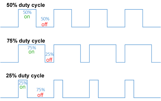
Analogy: The Light Switch
Imagine you are controlling a room light with a simple ON/OFF switch.
- If you leave the switch OFF, the room is dark (0% duty cycle).
- If you leave the switch ON, the room is fully lit (100% duty cycle).Now, imagine you could flick the switch ON and OFF very rapidly. If you flick it ON for a short duration and OFF for a longer duration within a fixed time interval (say, 1/10th of a second), your eyes would perceive the light as being dim. If you flick it ON for a longer duration and OFF for a shorter duration in that same interval, the light would appear brighter. This rapid switching, controlling the proportion of ON time, is the essence of PWM. The “average” brightness you perceive is analogous to the average voltage a device sees from a PWM signal.
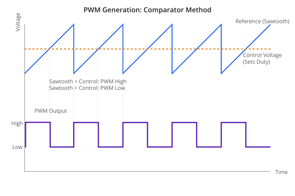
How is PWM Generated?
Conceptually, a PWM signal can be generated by comparing a reference signal (often a sawtooth or triangle wave) with a desired control voltage (the level that determines the duty cycle). When the reference signal’s voltage is less than the control voltage, the PWM output is high; otherwise, it’s low (or vice-versa depending on the design).
PWM on ESP32 Microcontrollers
ESP32 series SoCs are equipped with dedicated hardware peripherals for generating PWM signals efficiently without consuming significant CPU resources. The two primary peripherals are:
- LEDC (LED Control) Peripheral:
- Designed primarily for LED control applications, such as dimming and color mixing, but versatile enough for other general-purpose PWM tasks.
- It features configurable timers to set the PWM frequency and channels to control the duty cycle on specific GPIO pins.
- It supports multiple independent channels and different duty cycle resolutions.
- This peripheral will be our main focus for general PWM generation in this chapter and will be explored in greater depth in Chapter 145.
- MCPWM (Motor Control PWM) Peripheral:
- A more advanced and complex peripheral tailored for applications requiring precise control of motors (DC, brushless DC, stepper) and power converters.
- It offers features like dead-time generation (critical for H-bridge control to prevent shoot-through), fault detection, capture units, and synchronization capabilities.
- While extremely powerful, its complexity makes it more suitable for specialized motor control scenarios. We will briefly touch upon it but focus on LEDC for introductory PWM.
| Feature | LEDC (LED Control) Peripheral | MCPWM (Motor Control PWM) Peripheral |
|---|---|---|
| Primary Design Purpose | LED dimming, color mixing, general-purpose PWM tasks. | Precise control of motors (DC, BLDC, Stepper), power converters. |
| Complexity | Simpler, easier to configure for common tasks. | More advanced and complex, with specialized features. |
| Key Features |
– Configurable timers for frequency. – Multiple independent channels for duty cycle control. – Adjustable duty cycle resolution. – High-speed and Low-speed modes. |
– Dead-time generation (for H-bridges). – Fault detection inputs. – Capture units for feedback (e.g., Hall sensors). – Synchronization capabilities. – Carrier modulation. |
| Typical Use Cases |
– LED brightness control. – Simple fan speed control. – Generating signals for standard servo motors. – DAC-like analog voltage simulation. |
– Driving H-bridges for DC motors. – Controlling Brushless DC (BLDC) motors. – Controlling stepper motors (with appropriate drivers). – Switched-Mode Power Supply (SMPS) control. |
| Availability on RISC-V Variants (e.g., ESP32-C3/C6/H2) | Generally available (may have unified HS/LS modes). | Not available. These variants rely on LEDC or LP_PWM. |
For most common PWM tasks like LED dimming, simple motor speed control (not requiring advanced features), or generating signals for servos, the LEDC peripheral is sufficient and easier to configure.
LEDC Peripheral: A Brief Overview
The LEDC peripheral consists of the following main components:
- Timers: These are the heart of the PWM generation, responsible for setting the base frequency of the PWM signal. Each timer can be configured with a specific frequency and duty cycle resolution.
- Channels: These link a timer to an output GPIO pin. Each channel is configured to use a specific timer as its source, and its primary role is to control the duty cycle of the PWM signal output on its assigned GPIO.
- Duty Resolution: This determines the number of discrete steps available for setting the duty cycle. For example, a 10-bit resolution allows for 210 = 1024 steps (from 0 to 1023). A higher resolution allows for finer control over the duty cycle.
- Speed Modes: LEDC timers and channels can operate in either High-Speed (HS) or Low-Speed (LS) mode. This allows for flexibility in resource allocation and power management. HS timers can only be used with HS channels, and LS timers with LS channels.
The basic workflow for using LEDC involves:
- Configuring a timer (setting frequency and resolution).
- Configuring a channel (assigning it to a GPIO, linking it to a timer, and setting an initial duty cycle).
- Optionally, updating the duty cycle dynamically.
graph TD
    A[Start: Configure LEDC PWM] --> B{Define LEDC Parameters};
    style A fill:#EDE9FE,stroke:#5B21B6,stroke-width:2px,color:#5B21B6
    style B fill:#FEF3C7,stroke:#D97706,stroke-width:1px,color:#92400E

    B --> C["1- Configure LEDC Timer <br> <br> Set: <br> - Speed Mode (HS/LS) <br> - Timer Number <br> - Duty Resolution <br> - Frequency (Hz) <br> - Clock Source (e.g., LEDC_AUTO_CLK) <br> <br> Function: <i>ledc_timer_config()</i>"];
    style C fill:#DBEAFE,stroke:#2563EB,stroke-width:1px,color:#1E40AF

    C --> D["2- Configure LEDC Channel <br> <br> Set: <br> - Speed Mode (match timer) <br> - Channel Number <br> - Timer Select (link to timer) <br> - GPIO for output <br> - Initial Duty Cycle <br> - Hpoint (usually 0) <br> <br> Function: <i>ledc_channel_config()</i>"];
    style D fill:#DBEAFE,stroke:#2563EB,stroke-width:1px,color:#1E40AF

    D --> E{Need to Change Duty Cycle?};
    style E fill:#FEF3C7,stroke:#D97706,stroke-width:1px,color:#92400E

    E -- Yes --> F["3- Set New Duty Cycle <br> <br> Function: <i>ledc_set_duty()</i>"];
    style F fill:#DBEAFE,stroke:#2563EB,stroke-width:1px,color:#1E40AF

    F --> G["4- Apply Duty Cycle Change <br> <br> Function: <i>ledc_update_duty()</i>"];
    style G fill:#DBEAFE,stroke:#2563EB,stroke-width:1px,color:#1E40AF

    G --> H{Continue Operation / Further Changes?};
    style H fill:#FEF3C7,stroke:#D97706,stroke-width:1px,color:#92400E

    H -- Yes --> E;
    E -- No --> I[PWM Signal Outputting on GPIO];
    H -- No / End Task --> I;
    style I fill:#D1FAE5,stroke:#059669,stroke-width:2px,color:#065F46

    %% Mermaid class definitions for styling (optional if using inline styles extensively)
    classDef startNode fill:#EDE9FE,stroke:#5B21B6,stroke-width:2px,color:#5B21B6;
    classDef processNode fill:#DBEAFE,stroke:#2563EB,stroke-width:1px,color:#1E40AF;
    classDef decisionNode fill:#FEF3C7,stroke:#D97706,stroke-width:1px,color:#92400E;
    classDef endNode fill:#D1FAE5,stroke:#059669,stroke-width:2px,color:#065F46;
    classDef checkNode fill:#FEE2E2,stroke:#DC2626,stroke-width:1px,color:#991B1B;
Practical Examples
Let’s put theory into practice by generating a PWM signal to control the brightness of an LED.
Example 1: Dimming an LED using LEDC
In this example, we will configure an LEDC channel to output a PWM signal to an LED. We will then programmatically change the duty cycle to make the LED fade in and out.
Hardware Required:
- ESP32 development board (any variant supporting LEDC).
- One LED.
- One current-limiting resistor (e.g., 220Ω – 330Ω, depending on your LED’s specifications).
- Breadboard and jumper wires.
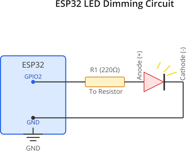
Connections:
- Connect the ESP32’s GND pin to one rail of the breadboard (the ground rail).
- Connect the chosen GPIO pin (e.g., GPIO2 for this example) to the positive (anode) leg of the LED through the current-limiting resistor.
- Connect the negative (cathode) leg of the LED to the ground rail on the breadboard.
Software:
Create a new ESP-IDF project in VS Code. Replace the content of your main.c file with the following code:
#include <stdio.h>
#include "freertos/FreeRTOS.h"
#include "freertos/task.h"
#include "driver/ledc.h"
#include "esp_err.h"

// Define the GPIO pin for the LED
#define LEDC_OUTPUT_GPIO (2) // Example: GPIO2. Choose an appropriate GPIO for your board.

// LEDC Configuration
#define LEDC_TIMER              LEDC_TIMER_0
#define LEDC_MODE               LEDC_HIGH_SPEED_MODE // Or LEDC_LOW_SPEED_MODE
#define LEDC_CHANNEL            LEDC_CHANNEL_0
#define LEDC_DUTY_RES           LEDC_TIMER_10_BIT // Set duty resolution to 10 bits (0-1023)
#define LEDC_FREQUENCY          (5000) // Frequency in Hertz (5 kHz)

void app_main(void)
{
    // 1. Configure LEDC Timer
    ledc_timer_config_t ledc_timer = {
        .speed_mode       = LEDC_MODE,
        .timer_num        = LEDC_TIMER,
        .duty_resolution  = LEDC_DUTY_RES,
        .freq_hz          = LEDC_FREQUENCY,
        .clk_cfg          = LEDC_AUTO_CLK // Automatically select the clock source
    };
    ESP_ERROR_CHECK(ledc_timer_config(&ledc_timer));
    printf("LEDC timer configured.\n");

    // 2. Configure LEDC Channel
    ledc_channel_config_t ledc_channel = {
        .speed_mode     = LEDC_MODE,
        .channel        = LEDC_CHANNEL,
        .timer_sel      = LEDC_TIMER,
        .intr_type      = LEDC_INTR_DISABLE, // No interrupt
        .gpio_num       = LEDC_OUTPUT_GPIO,
        .duty           = 0, // Initial duty cycle (0%)
        .hpoint         = 0  // Phase = 0
    };
    ESP_ERROR_CHECK(ledc_channel_config(&ledc_channel));
    printf("LEDC channel configured for GPIO %d.\n", LEDC_OUTPUT_GPIO);

    // 3. Gradually change duty cycle to fade LED
    printf("Starting LED fade example...\n");
    uint32_t max_duty = (1 << LEDC_DUTY_RES) - 1; // Max duty value for the configured resolution (1023 for 10-bit)

    while (1) {
        // Fade In
        for (uint32_t duty = 0; duty <= max_duty; duty += 10) { // Increment by a small step
            ESP_ERROR_CHECK(ledc_set_duty(LEDC_MODE, LEDC_CHANNEL, duty));
            ESP_ERROR_CHECK(ledc_update_duty(LEDC_MODE, LEDC_CHANNEL));
            vTaskDelay(pdMS_TO_TICKS(20)); // Delay for visibility
        }
        printf("LED Faded In (Max Brightness)\n");

        // Fade Out
        for (uint32_t duty = max_duty; duty > 0; duty -= 10) { // Decrement by a small step
            ESP_ERROR_CHECK(ledc_set_duty(LEDC_MODE, LEDC_CHANNEL, duty));
            ESP_ERROR_CHECK(ledc_update_duty(LEDC_MODE, LEDC_CHANNEL));
            vTaskDelay(pdMS_TO_TICKS(20));
        }
        // Ensure duty is set to 0 at the end of fade out
        ESP_ERROR_CHECK(ledc_set_duty(LEDC_MODE, LEDC_CHANNEL, 0));
        ESP_ERROR_CHECK(ledc_update_duty(LEDC_MODE, LEDC_CHANNEL));
        printf("LED Faded Out (Min Brightness)\n");

        vTaskDelay(pdMS_TO_TICKS(500)); // Wait before repeating
    }
}
Code Explanation:
- Includes:
driver/ledc.h: Header for the LEDC driver.esp_err.h: For ESP error checking utilities.
- Defines:
LEDC_OUTPUT_GPIO: The GPIO pin connected to the LED. Ensure this GPIO is valid for LEDC output on your specific ESP32 variant and board.LEDC_TIMER: Specifies which LEDC timer to use (e.g.,LEDC_TIMER_0).LEDC_MODE:LEDC_HIGH_SPEED_MODEorLEDC_LOW_SPEED_MODE.LEDC_CHANNEL: Specifies which LEDC channel to use (e.g.,LEDC_CHANNEL_0).LEDC_DUTY_RES: Sets the resolution for the duty cycle.LEDC_TIMER_10_BITmeans the duty cycle can be set from 0 to 1023.LEDC_FREQUENCY: The desired PWM frequency in Hz (e.g., 5000 Hz = 5 kHz).
app_main()function:- Timer Configuration (
ledc_timer_config_t):speed_mode: Must match the channel’s speed mode.timer_num: The timer to configure.duty_resolution: Precision of the duty cycle.freq_hz: Target PWM frequency.clk_cfg:LEDC_AUTO_CLKlets ESP-IDF choose an appropriate clock source (APB_CLK or REF_TICK).ledc_timer_config(): Applies the timer configuration.
- Channel Configuration (
ledc_channel_config_t):speed_mode: Must match the timer’s speed mode.channel: The channel to configure.timer_sel: Links this channel to the previously configured timer.intr_type: Interrupt type (disabled for this simple example).gpio_num: The GPIO pin to output the PWM signal.duty: Initial duty cycle value. For 10-bit resolution, 0 is 0% and 1023 is 100%.hpoint: Horizontal point, typically 0 for standard PWM. It’s used for phase shifting.ledc_channel_config(): Applies the channel configuration.
- Fading Loop:
max_duty: Calculates the maximum duty value based on the resolution (e.g., 210 – 1 = 1023).- The
while(1)loop continuously fades the LED in and out. ledc_set_duty(): Sets the new duty cycle for the specified channel.ledc_update_duty(): Applies the duty cycle change. This function is crucial for the new duty cycle to take effect.vTaskDelay(): Adds a small delay to make the fading effect visible.
- Timer Configuration (
Build Instructions:
- Save the
main.cfile. - Open the ESP-IDF terminal in VS Code (Terminal > New Terminal, then ensure the ESP-IDF environment is activated).
- Navigate to your project directory.
- Build the project:
idf.py build
Run/Flash/Observe Steps:
- Connect your ESP32 board to your computer.
- Flash the project:
idf.py -p (YourCOMPort) flash(replace(YourCOMPort)with your ESP32’s serial port, e.g.,COM3or/dev/ttyUSB0). - Monitor the output:
idf.py -p (YourCOMPort) monitor - Observe: You should see the LED connected to
LEDC_OUTPUT_GPIOgradually brighten and dim, repeating the cycle. The serial monitor will print messages indicating the progress.
Tip: If the LED doesn’t light up or the brightness doesn’t change, double-check your wiring, the GPIO pin number, and the resistor value. Also, ensure the chosen GPIO is not used by other peripherals (like JTAG by default on some pins).
Example 2: Conceptual Servo Motor Control
Servo motors are commonly used in robotics and hobbyist projects to control the angular position of a mechanical part. Standard hobby servos are typically controlled by a PWM signal with a frequency of 50 Hz (a period of 20 ms). The width of the pulse within this 20 ms period determines the servo’s angle:
- ~1 ms pulse width: 0 degrees (minimum angle).
- ~1.5 ms pulse width: 90 degrees (neutral/center position).
- ~2 ms pulse width: 180 degrees (maximum angle).
The LEDC peripheral can be configured to generate these signals.
Conceptual Code Snippet (Illustrative – not a full servo library):
// --- Assumed LEDC Timer and Channel already configured for 50Hz ---
// For 50Hz and 10-bit resolution (1024 steps over 20ms):
// Each step = 20ms / 1024 = ~19.53 µs
// Target 1ms pulse (0 degrees) = 1000 µs / 19.53 µs/step ≈ 51 steps
// Target 1.5ms pulse (90 degrees) = 1500 µs / 19.53 µs/step ≈ 77 steps
// Target 2ms pulse (180 degrees) = 2000 µs / 19.53 µs/step ≈ 102 steps

// Function to set servo angle (approximate)
void set_servo_angle(uint8_t angle_degrees) {
    // Ensure angle is within 0-180
    if (angle_degrees > 180) angle_degrees = 180;

    // Map angle (0-180) to duty cycle (e.g., 51-102 for 10-bit @ 50Hz)
    // This mapping needs to be precise for your specific servo and resolution
    uint32_t min_duty_for_servo = 51; // Corresponds to ~1ms
    uint32_t max_duty_for_servo = 102; // Corresponds to ~2ms

    uint32_t duty = min_duty_for_servo + ((max_duty_for_servo - min_duty_for_servo) * angle_degrees) / 180;

    ESP_ERROR_CHECK(ledc_set_duty(LEDC_MODE, LEDC_CHANNEL, duty)); // Assuming LEDC_MODE and LEDC_CHANNEL are defined
    ESP_ERROR_CHECK(ledc_update_duty(LEDC_MODE, LEDC_CHANNEL));
    printf("Servo angle set to %d degrees (duty: %lu)\n", angle_degrees, duty);
}

// In app_main, after LEDC setup:
// set_servo_angle(0);   // Go to 0 degrees
// vTaskDelay(pdMS_TO_TICKS(1000));
// set_servo_angle(90);  // Go to 90 degrees
// vTaskDelay(pdMS_TO_TICKS(1000));
// set_servo_angle(180); // Go to 180 degrees
Warning: The exact duty cycle values for 0, 90, and 180 degrees can vary slightly between servo motor models. Calibration is often required for precise control. This conceptual example illustrates how LEDC can generate the necessary signals, but a robust servo library would handle timing and calibration more meticulously.
Variant Notes
The LEDC and MCPWM peripherals are available on most ESP32 variants, but there can be differences in the number of channels, timers, and specific GPIOs that can be used.
| Feature | ESP32 (Classic) | ESP32-S2 | ESP32-S3 | ESP32-C3 | ESP32-C6 | ESP32-H2 |
|---|---|---|---|---|---|---|
| LEDC Timers | 4 HS, 4 LS | 4 HS, 4 LS | 4 HS, 4 LS | 4 (shared HS/LS) | 4 (shared HS/LS) | 2 (shared HS/LS) |
| LEDC Channels | 8 HS, 8 LS | 8 HS, 8 LS | 8 HS, 8 LS | 6 (shared HS/LS) | 8 (shared HS/LS) | 4 (shared HS/LS) |
| MCPWM Units | 2 units | 1 unit | 2 units | 0 units | 0 units | 0 units |
| LP PWM | No | No | No | No | Yes (1 unit, 6 ch) | Yes (1 unit, 2 ch) |
| GPIO Matrix for PWM | Most GPIOs < 34 | Most GPIOs | Most GPIOs | Most GPIOs | Most GPIOs | Most GPIOs |
Key Considerations:
- LEDC Timers/Channels:
- ESP32, ESP32-S2, ESP32-S3 have distinct High-Speed (HS) and Low-Speed (LS) timers/channels. HS timers can only drive HS channels, and LS timers can only drive LS channels.
- ESP32-C3, ESP32-C6, ESP32-H2 have a unified set of timers and channels that can be configured for either HS or LS mode, but the total number is fixed. For example, ESP32-C3 has 6 channels that can be individually configured as HS or LS, drawing from 4 timers that can also be HS or LS.
- MCPWM: The MCPWM peripheral is not available on RISC-V based variants like ESP32-C3, ESP32-C6, and ESP32-H2. These variants rely on LEDC or the new LP_PWM for PWM generation.
- LP_PWM (Low-Power PWM): ESP32-C6 and ESP32-H2 introduce a new Low-Power PWM peripheral. This is designed for applications requiring PWM generation during light sleep modes, offering better power efficiency for such use cases. Its API and capabilities differ from LEDC.
- GPIO Availability: While the GPIO matrix allows flexible routing of peripherals to pins, always consult the datasheet for your specific ESP32 variant to confirm which GPIOs are recommended or have limitations for PWM output (e.g., some pins might be input-only, strapping pins, or have high capacitive loads). Generally, most digital GPIOs can be used.
- API Consistency: The LEDC driver API (
driver/ledc.h) is largely consistent across variants that support LEDC. However, the underlying number of resources (timers, channels) changes.
When developing, always refer to the latest ESP-IDF documentation and the specific datasheet for your target ESP32 variant to ensure compatibility and optimal configuration.
Common Mistakes & Troubleshooting Tips
| Mistake / Issue | Symptom(s) | Troubleshooting / Solution |
|---|---|---|
| Incorrect GPIO Selection or Wiring |
– LED does not light up or is always ON/OFF. – Servo motor jitters or doesn’t move. – ESP32 behaves erratically or fails to boot (if strapping pin used). |
– Verify GPIO: Consult ESP32 variant datasheet for valid PWM output pins. Avoid strapping pins (e.g., GPIO0, GPIO2 during boot if not careful) or pins used by other peripherals (JTAG, SPI flash). – Check Wiring: Ensure correct LED polarity (anode to GPIO via resistor, cathode to GND). Confirm resistor value is appropriate. For servos, check VCC, GND, and Signal connections. |
| Mismatched Speed Modes for Timer and Channel |
– ledc_timer_config() or ledc_channel_config() returns an error. – No PWM output, or unexpected behavior. |
– (For ESP32, S2, S3): Ensure speed_mode in ledc_timer_config_t and ledc_channel_config_t are identical (both LEDC_HIGH_SPEED_MODE or both LEDC_LOW_SPEED_MODE). – (For C3, C6, H2): Timers/channels are shared; ensure consistent mode selection if applicable based on overall design. |
| Forgetting ledc_update_duty() | – Initial duty cycle works, but subsequent calls to ledc_set_duty() do not change the LED brightness or servo position. | – Always call ledc_update_duty(LEDC_MODE, LEDC_CHANNEL) immediately after ledc_set_duty(LEDC_MODE, LEDC_CHANNEL, new_duty_value) for the change to take effect. |
| Duty Cycle Calculation Errors or Resolution Misunderstanding |
– LED brightness is not as expected (too dim, too bright, not scaling linearly). – Servo moves to incorrect angles. |
– Max duty value = (1 << duty_resolution_bits) - 1. (e.g., for 10-bit, max is 1023). – Duty for X% = (X / 100.0) * max_duty_value. – Ensure the calculated duty value does not exceed the maximum. |
| Frequency vs. Resolution Trade-offs Ignored |
– PWM output is unstable, frequency is incorrect, or actual resolution is lower than configured. – ledc_timer_config() might return an error if combination is impossible. |
– Higher frequency might require lower resolution, and vice-versa. The formula is approx: freq_hz = clk_source_freq / (1 << duty_resolution). – Use LEDC_AUTO_CLK and check documentation for limits. If issues persist, try reducing frequency or resolution. |
| Incorrect Resistor for LED |
– LED is very dim or burns out quickly. – ESP32 GPIO pin might be damaged due to overcurrent. |
– Always use a current-limiting resistor with LEDs. Calculate value using Ohm’s Law: R = (V_source – V_fwd_LED) / I_fwd_LED. Common values are 220Ω to 330Ω for standard LEDs with 3.3V GPIOs. |
| Servo Power Issues | – Servo jitters, doesn’t move, or resets the ESP32. | – Servos can draw significant current. Powering a servo directly from an ESP32 GPIO pin (for VCC) is generally not recommended, especially for larger servos. Use a separate, adequate power supply for the servo, ensuring a common ground with the ESP32. |
Exercises
- Breathing LED: Modify the LED dimming example to create a “breathing” effect where the LED smoothly fades in and then smoothly fades out, continuously. (Hint: The provided example already does this, but try to adjust the step size and delay for different breathing speeds).
- Dual LED Control: Configure two different LEDs on two different GPIO pins. Control their brightness independently using two separate LEDC channels. Make one LED brighter while the other is dimmer, and then swap their brightness levels.
- Specific PWM Signal: Calculate the LEDC timer and duty settings required to generate a 1 kHz PWM signal with a precise 25% duty cycle. Use a 12-bit duty resolution. Implement this, and if you have an LED, observe its brightness (it should be relatively dim).
- PWM in Audio: Research and write a short paragraph explaining how PWM is utilized in Class-D audio amplifiers to efficiently drive speakers.
- Oscilloscope Verification (Advanced): If you have access to an oscilloscope, connect its probe to the GPIO pin outputting the PWM signal in the LED dimming example. Observe the waveform. Verify that the frequency matches your configuration (e.g., 5 kHz). Manually set a fixed duty cycle (e.g., 25%, 50%, 75%) and verify the pulse width changes accordingly on the oscilloscope.
Summary
- Pulse Width Modulation (PWM) is a technique to control analog devices using a digital signal by varying the ON time (pulse width) of a square wave while keeping its frequency constant.
- Key parameters are Period, Frequency, and Duty Cycle (percentage of ON time).
- ESP32 microcontrollers feature dedicated hardware for PWM: LEDC (for general-purpose PWM, LED control) and MCPWM (for advanced motor control). Newer variants like ESP32-C6/H2 also have LP_PWM.
- The LEDC peripheral uses timers (to set frequency and resolution) and channels (to output PWM on a GPIO and control duty cycle).
- Configuration involves setting up an LEDC timer (
ledc_timer_config_t) and an LEDC channel (ledc_channel_config_t). - The duty cycle is set using
ledc_set_duty()and applied withledc_update_duty(). - PWM is widely used for LED dimming, motor speed control, servo motor positioning, and generating analog-like voltage levels.
- Different ESP32 variants have varying numbers of LEDC/MCPWM resources; always check the datasheet.
Further Reading
- ESP-IDF LEDC Driver Documentation:
- ESP-IDF MCPWM Driver Documentation:
- ESP-IDF MCPWM API Reference (Check for variant availability).
- ESP-IDF LP_PWM Driver Documentation (for ESP32-C6, ESP32-H2, etc.):
- Refer to the specific variant’s peripheral documentation in the ESP-IDF API reference.
- General Article on PWM:
- Wikipedia: Pulse-width modulation
- Many electronics tutorial websites (e.g., SparkFun, Adafruit) have excellent articles explaining PWM.
