
Chapter 143: RMT for WS2812/NeoPixel LED Control
Chapter Objectives
After completing this chapter, you will be able to:
- Understand the working principle of WS2812/NeoPixel addressable LEDs.
- Describe the WS2812B timing protocol for data transmission.
- Represent LED colors in RGB format and prepare them for WS2812 transmission (GRB order).
- Configure the RMT TX channel to generate WS2812B-compliant control signals.
- Utilize RMT encoders, particularly the
bytes_encoder, to convert color data into RMT symbols. - Write ESP-IDF v5.x applications to control a strip of WS2812 LEDs, setting individual colors and creating simple animations.
- Understand power supply considerations for WS2812 LED strips.
- Be aware of common issues and troubleshooting techniques when working with WS2812 LEDs and ESP32.
Introduction
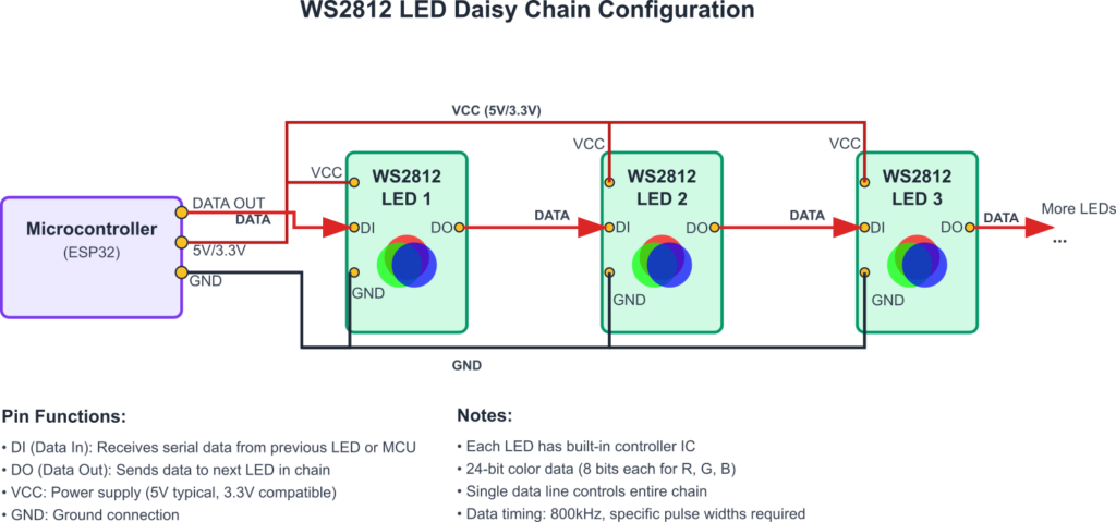
Individually addressable RGB LEDs, popularly known by brand names like NeoPixel (from Adafruit) which often use controllers like the WS2812, WS2812B, SK6812, etc., have revolutionized how we add dynamic lighting to projects. These LEDs allow for complex lighting effects with minimal wiring – typically just power, ground, and a single data line. Each LED in a strip or matrix contains a small microcontroller that receives color data, displays its assigned color, and then passes the remaining data down the chain to the next LED.
The control protocol for these LEDs relies on very specific pulse timings, making them an excellent candidate for the ESP32’s RMT (Remote Control) peripheral. While bit-banging the protocol is possible, it’s CPU-intensive and can be unreliable in a multitasking environment like FreeRTOS. The RMT peripheral can offload this task, generating the precise waveforms with hardware accuracy and freeing up the CPU for other tasks.
In this chapter, we will dive into the specifics of the WS2812B protocol (one of the most common types) and learn how to use the ESP-IDF’s RMT driver to control these vibrant LEDs, bringing colorful displays to your ESP32 projects.
Theory
WS2812/NeoPixel Basics
- Individually Addressable: Each LED in a chain can be set to a unique color and brightness.
- Integrated Controller: Each LED package contains a small IC (like the WS2812B) that handles the protocol, color data storage (3 x 8-bit registers for RGB), and PWM drive for its internal red, green, and blue LEDs.
- Data Line: A single data line is used to send color information to all LEDs in a chain.
- Daisy-Chaining: LEDs are connected in a series. The
Data Out(DO) pin of one LED connects to theData In(DI) pin of the next. The first LED in the chain receives data from the microcontroller. - Data Propagation: When an LED receives data, it “latches” the first 24 bits of color information intended for it, then passes the rest of the data stream along to the next LED. This continues down the chain.
graph TD
    subgraph "WS2812 LED Strip - Data Flow"
        MCU["ESP32 Microcontroller <br> (RMT TX Output on GPIO)"] -->|"Data Stream (GRB for LED1, LED2, LED3...)"| LED1_DI((DI));

        subgraph "LED 1"
            direction LR
            LED1_DI --> LED1_IC[Internal Controller <br> & RGB LED];
            LED1_IC -- Latches 24 bits (G1,R1,B1) --> LED1_Display[Displays Its Color];
            LED1_IC -- Passes Remaining Data --> LED1_DO((DO));
        end
        style LED1_DI fill:#EDE9FE,stroke:#5B21B6,stroke-width:2px,color:#5B21B6;
        style LED1_DO fill:#EDE9FE,stroke:#5B21B6,stroke-width:2px,color:#5B21B6;
        style LED1_IC fill:#DBEAFE,stroke:#2563EB,stroke-width:1px,color:#1E40AF;
        style LED1_Display fill:#D1FAE5,stroke:#059669,stroke-width:1px,color:#065F46;

        LED1_DO -->|"Data Stream (GRB for LED2, LED3...)"| LED2_DI((DI));

        subgraph "LED 2"
            direction LR
            LED2_DI --> LED2_IC[Internal Controller <br> & RGB LED];
            LED2_IC -- Latches 24 bits (G2,R2,B2) --> LED2_Display[Displays Its Color];
            LED2_IC -- Passes Remaining Data --> LED2_DO((DO));
        end
        style LED2_DI fill:#EDE9FE,stroke:#5B21B6,stroke-width:2px,color:#5B21B6;
        style LED2_DO fill:#EDE9FE,stroke:#5B21B6,stroke-width:2px,color:#5B21B6;
        style LED2_IC fill:#DBEAFE,stroke:#2563EB,stroke-width:1px,color:#1E40AF;
        style LED2_Display fill:#D1FAE5,stroke:#059669,stroke-width:1px,color:#065F46;

        LED2_DO -->|"Data Stream (GRB for LED3...)"| LED3_DI((DI));

        subgraph "LED 3 (and so on...)"
            direction LR
            LED3_DI --> LED3_IC[Internal Controller <br> & RGB LED];
            LED3_IC -- Latches 24 bits (G3,R3,B3) --> LED3_Display[Displays Its Color];
            LED3_IC -- Passes Remaining Data --> LED3_DO((DO));
        end
        style LED3_DI fill:#EDE9FE,stroke:#5B21B6,stroke-width:2px,color:#5B21B6;
        style LED3_DO fill:#EDE9FE,stroke:#5B21B6,stroke-width:2px,color:#5B21B6;
        style LED3_IC fill:#DBEAFE,stroke:#2563EB,stroke-width:1px,color:#1E40AF;
        style LED3_Display fill:#D1FAE5,stroke:#059669,stroke-width:1px,color:#065F46;

        LED3_DO --> MoreLEDs[... To Next LED or End of Strip];
        style MoreLEDs fill:#FEF3C7,stroke:#D97706,stroke-width:1px,color:#92400E;

        Note1[Note: VCC and GND connections to all LEDs are omitted for clarity on data flow.]
        style Note1 fill:#F3F4F6,stroke:#9CA3AF,color:#4B5563,stroke-dasharray:5 5;
    end
WS2812B Data Protocol and Timings
The WS2812B (a very common variant) uses a specific one-wire protocol where data bits (0 or 1) are encoded by the duration of high and low pulses. The data is sent as a stream of 24-bit color values (8 bits for Green, 8 bits for Red, 8 bits for Blue – GRB order) for each LED, one after another.
Timings (for WS2812B, typically running at 800kHz data rate):
The total period for one bit is approximately 1.25µs.
| Signal Component | Parameter | Typical Duration (µs) | Typical Tolerance (µs) | RMT Ticks (@10MHz resolution, 1 tick=0.1µs) |
|---|---|---|---|---|
| Logical ‘0’ | T0H (High Time) | 0.35 – 0.4 | ±0.15 | 3 – 4 |
| T0L (Low Time) | 0.8 – 0.9 | ±0.15 | 8 – 9 | |
| Logical ‘1’ | T1H (High Time) | 0.7 – 0.8 | ±0.15 | 7 – 8 |
| T1L (Low Time) | 0.45 – 0.6 | ±0.15 | 4 – 6 | |
| Total Bit Period (T0H+T0L or T1H+T1L) | – | ~1.25 | – | ~12 – 13 |
| Reset Code (RES) | Low Time | >50 (older chips) >280 (newer chips) |
– | >500 / >2800 |
Timings are typical for WS2812B at an 800kHz data rate. Always consult the specific datasheet for your LED variant.
RMT tick values are examples and depend on the chosen resolution_hz. The example uses 1 tick = 0.1µs (100ns).
|
||||

Data Format:
- Each LED requires 24 bits of color data.
- The order is typically Green-Red-Blue (GRB), most significant bit (MSB) first for each color component.
- Example:
G7G6G5G4G3G2G1G0 R7R6R5R4R3R2R1R0 B7B6B5B4B3B2B1B0
- Example:
- To control a strip of
NLEDs, you sendN * 24bits of data followed by a Reset pulse.
sequenceDiagram
    participant MCU as ESP32 (RMT TX)
    participant LED1 as LED 1
    participant LED2 as LED 2
    participant LEDN as LED N

    MCU->>LED1: GRB Data for LED1 (24 bits)
    MCU->>LED1: GRB Data for LED2 (24 bits)
    MCU->>LED1: ...
    MCU->>LED1: GRB Data for LEDN (24 bits)

    activate LED1
    LED1-->>LED1: Latch G1,R1,B1
    LED1->>LED2: GRB Data for LED2 (24 bits)
    LED1->>LED2: ...
    LED1->>LED2: GRB Data for LEDN (24 bits)
    deactivate LED1

    activate LED2
    LED2-->>LED2: Latch G2,R2,B2
    LED2->>LEDN: ...
    LED2->>LEDN: GRB Data for LEDN (24 bits)
    deactivate LED2

    activate LEDN
    LEDN-->>LEDN: Latch GN,RN,BN
    deactivate LEDN

    Note over MCU,LEDN: After all data is sent...
    MCU-->>LED1: RESET Pulse (>50µs Low)
    MCU-->>LED2: RESET Pulse (>50µs Low)
    MCU-->>LEDN: RESET Pulse (>50µs Low)

    LED1-->>LED1: Display Latched Color
    LED2-->>LED2: Display Latched Color
    LEDN-->>LEDN: Display Latched Color
Warning: Always check the datasheet for your specific LED variant (WS2812, WS2812B, SK6812, etc.) as timings can vary slightly. The GRB order is common for WS2812B, but other types might use RGB or other orders.
Mapping WS2812B Timings to RMT Symbols
To use the RMT peripheral, we need to convert these WS2812B pulse timings into rmt_symbol_word_t items. Each bit of the 24-bit color data will be represented by one RMT symbol, defining its high pulse and low pulse.
Let’s assume an RMT channel resolution_hz that allows us to achieve the required sub-microsecond precision. A common choice is a high resolution like 10MHz (1 tick = 0.1µs = 100ns) or even higher if supported and necessary for finer tuning. The ESP-IDF RMT driver often uses a default clock that provides sufficient resolution (e.g., APB_CLK divided). For WS2812B, the APB clock (typically 80MHz) can be divided to get a resolution that works well. For example, if resolution_hz is set to 10,000,000 Hz (10 MHz), then 1 RMT tick = 0.1 µs.
- T0H (0.4µs):
duration0 = 4ticks,level0 = 1 - T0L (0.85µs):
duration1 = 8or9ticks,level1 = 0- So, a ‘0’ bit:
{.duration0 = 4, .level0 = 1, .duration1 = 9, .level1 = 0}(using 0.4µs and 0.9µs as example targets)
- So, a ‘0’ bit:
- T1H (0.8µs):
duration0 = 8ticks,level0 = 1 - T1L (0.45µs):
duration1 = 4or5ticks,level1 = 0- So, a ‘1’ bit:
{.duration0 = 8, .level0 = 1, .duration1 = 5, .level1 = 0}(using 0.8µs and 0.5µs as example targets)
- So, a ‘1’ bit:
The exact tick values need to be tuned based on the chosen resolution_hz and the specific timings from the LED datasheet. The ESP-IDF includes a built-in led_strip component that handles these conversions and provides a higher-level API, but understanding the RMT symbol mapping is valuable.
RMT Encoders for WS2812
While you could manually create an array of rmt_symbol_word_t for each bit of each LED, this is cumbersome. The RMT driver’s encoder system simplifies this. For WS2812, where we send a stream of bytes (3 bytes per LED), the rmt_bytes_encoder_t is particularly useful.
rmt_bytes_encoder_config_t:
| Parameter | Type | Description for WS2812B | Example Value (10MHz RMT) |
|---|---|---|---|
bit0 |
rmt_symbol_word_t |
Defines the RMT symbol (pulse pair) representing a logical ‘0’ data bit. This includes T0H and T0L timings. | {.level0=1, .duration0=4, .level1=0, .duration1=9} (T0H=0.4µs, T0L=0.9µs) |
bit1 |
rmt_symbol_word_t |
Defines the RMT symbol (pulse pair) representing a logical ‘1’ data bit. This includes T1H and T1L timings. | {.level0=1, .duration0=8, .level1=0, .duration1=5} (T1H=0.8µs, T1L=0.5µs) |
flags.msb_first |
uint32_t (bit field) |
Set to 1 if the bytes being encoded should be processed MSB (Most Significant Bit) first. For WS2812, each byte of color data (G, R, B) is sent MSB first. | 1 |
When you call rmt_transmit() with this encoder and your array of GRB color data (e.g., uint8_t pixel_data[] = {G1, R1, B1, G2, R2, B2, ...};), the encoder will iterate through each byte, and for each bit within that byte, it will select either the bit0 or bit1 RMT symbol and queue it for transmission.
The ESP-IDF also provides a dedicated led_strip component (which internally uses RMT) that offers an even higher-level API (e.g., led_strip_set_pixel(), led_strip_refresh()). For learning RMT fundamentals, directly using the RMT driver with a bytes encoder is instructive. For production projects, the led_strip component is often more convenient. This chapter will focus on using the RMT driver directly to illustrate the underlying mechanism.
graph TD
    subgraph "RMT TX Process for WS2812 LEDs"
        A["Application Defines <br> LED Colors (Array of GRB values) <br> e.g., <b>uint8_t</b> led_pixels[NUM_LEDS*3]"] --> B{"RMT Bytes Encoder <br> (Configured with WS2812 bit0/bit1 RMT symbols & MSB_first)"};
        style A fill:#DBEAFE,stroke:#2563EB,stroke-width:1px,color:#1E40AF
        style B fill:#FEF3C7,stroke:#D97706,stroke-width:1px,color:#92400E

        B -- Iterates through each byte & bit of GRB data --> C["Generates Stream of RMT Symbols <br> (<b>rmt_symbol_word_t</b> for each '0' or '1' bit)"];
        style C fill:#DBEAFE,stroke:#2563EB,stroke-width:1px,color:#1E40AF

        C --> D{"RMT TX Channel Hardware <br> (Configured with WS2812 <b>resolution_hz</b>)"};
        style D fill:#EDE9FE,stroke:#5B21B6,stroke-width:2px,color:#5B21B6

        D -- Sends pulse sequence via GPIO --> E["WS2812 Data Signal <br> (Precise High/Low Pulses)"];
        style E fill:#DBEAFE,stroke:#2563EB,stroke-width:1px,color:#1E40AF

        E --> F((LED Strip Receives Data <br> & Displays Colors after Reset Pulse));
        style F fill:#D1FAE5,stroke:#059669,stroke-width:2px,color:#065F46

        Note["Note: Reset pulse (long low) is typically achieved by bus idle time after rmt_transmit() completes and rmt_tx_wait_all_done() is called."]
        style Note fill:#F3F4F6,stroke:#9CA3AF,color:#4B5563,stroke-dasharray:5 5;
        D -.-> Note;
    end
Reset Pulse with RMT:
The reset pulse (long low) is typically handled by ensuring no RMT transmissions occur for the required duration. After rmt_transmit() finishes sending the color data, the RMT line will go to its idle state (usually low if not inverted). If this idle time is naturally longer than the reset period, it works. Alternatively, one could transmit a final “dummy” symbol with a very long low duration, or simply rely on the rmt_tx_wait_all_done() followed by a software delay if precise RMT-controlled reset timing is needed, though often the natural idle time after transmission suffices. The led_strip component handles this automatically.
Practical Example: Controlling a WS2812B LED Strip
This example demonstrates how to control a strip of WS2812B LEDs, setting them to a static color pattern.
1. Hardware Setup:
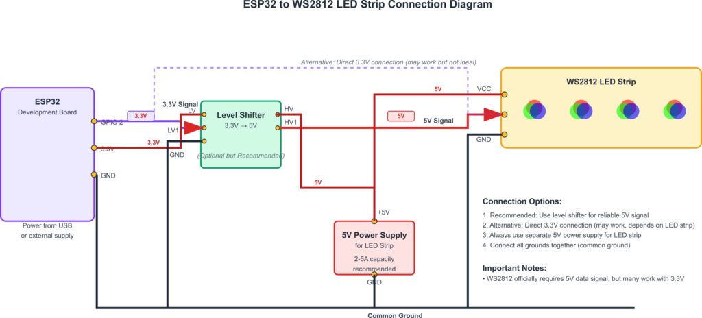
- WS2812B LED Strip: Connect:
GNDof the strip to ESP32GND.VCCor5Vof the strip to an appropriate 5V power supply.- > Warning: Powering more than a few LEDs directly from the ESP32’s 3.3V or 5V pin is NOT recommended. Each LED can draw up to 60mA at full brightness white. A dedicated, robust 5V power supply is essential for strips of any significant length. Ensure the ESP32’s GND is connected to the power supply’s GND.
Data In(DI) of the strip to the ESP32 GPIO pin defined byRMT_LED_STRIP_GPIO_NUM.
- Level Shifter (Recommended for 5V Strips): WS2812 LEDs are typically 5V devices. While some may work with the ESP32’s 3.3V logic signal, it’s often out of spec and can lead to unreliable behavior, flickering, or incorrect colors. Using a level shifter (e.g., 74AHCT125, SN74LVC1T45) to convert the ESP32’s 3.3V data signal to 5V is highly recommended for robust operation.
- Power Supply Considerations:
| Consideration | Details | Recommendation / Notes |
|---|---|---|
| Voltage | WS2812B LEDs typically operate at 5V. | Use a stable 5V power supply. ESP32’s 3.3V output is generally insufficient for VCC. |
| Current per LED | Up to ~60mA per LED at full brightness white (20mA per R, G, B channel). Average current is usually lower for typical colors and brightness levels. | Calculate total potential current: Number of LEDs * 60mA. Choose a power supply rated significantly above this. |
| Powering from ESP32 | Highly NOT recommended for more than a few (1-3) LEDs due to current limitations of ESP32’s VOUT pins. | Can lead to dim LEDs, flickering, ESP32 instability, or damage. Always prefer an external power supply. |
| External Power Supply | Dedicated 5V PSU with sufficient amperage. | Example: For 50 LEDs, max current ~3A (50*0.06A). A 5V 4A or 5A PSU would be a good choice. |
| Ground Connection | Crucial: The ground (GND) of the external LED power supply MUST be connected to the ESP32’s GND. | This common ground reference is essential for the data signal to be interpreted correctly. |
| Wire Gauge | For longer strips or high LED counts, power wires (VCC and GND) need to be adequately sized to handle the current and avoid voltage drop. | Use thicker wires for power lines, especially if injecting power at multiple points on a long strip. |
| Decoupling Capacitor | A large capacitor (e.g., 1000µF, 6.3V or higher) across VCC and GND of the LED strip, near the power input. | Helps to smooth out power supply fluctuations, especially during rapid changes in LED brightness/color. Place close to the strip. |
| Logic Level Shifting | ESP32 outputs 3.3V logic. WS2812B data input (DI) expects ~5V logic for reliable operation. | Use a logic level shifter (e.g., 74AHCT125, SN74LVC1T45) to convert the 3.3V data signal from ESP32 to 5V for the LED strip’s DI pin. Skipping this can lead to unreliable behavior. |
2. Project Setup:
Ensure the rmt component is in your main/CMakeLists.txt.
idf_component_register(...
                    REQUIRES esp_log rmt esp_common # esp_common for ESP_RETURN_ON_ERROR
                    ...)
3. Code (main/ws2812_control_main.c):
#include <stdio.h>
#include "freertos/FreeRTOS.h"
#include "freertos/task.h"
#include "esp_log.h"
#include "driver/rmt_tx.h"
#include "esp_check.h" // For ESP_RETURN_ON_ERROR

#define RMT_LED_STRIP_GPIO_NUM  GPIO_NUM_18 // GPIO connected to data line of WS2812
#define RMT_LED_STRIP_RESOLUTION_HZ 10000000 // 10MHz resolution, 1 tick = 0.1us (100ns)
#define NUM_LEDS                8           // Number of LEDs in your strip

// Define WS2812B timings in RMT ticks (based on 10MHz resolution)
// T0H: 0.4us => 4 ticks
// T0L: 0.85us => 8.5 ticks (use 8 or 9, adjust if needed)
// T1H: 0.8us => 8 ticks
// T1L: 0.45us => 4.5 ticks (use 4 or 5, adjust if needed)

// Using common timings that work for WS2812B with 10MHz RMT resolution:
#define WS2812_T0H_TICKS (4)  // 0.4us
#define WS2812_T0L_TICKS (9)  // 0.9us (Total 1.3us for '0')
#define WS2812_T1H_TICKS (8)  // 0.8us
#define WS2812_T1L_TICKS (5)  // 0.5us (Total 1.3us for '1')
// Note: Sum of T0H+T0L or T1H+T1L should be around 1.25us to 1.3us for 800kHz data rate.
// These values (4,9 and 8,5) sum to 1.3us.

#define RMT_TX_MEM_BLOCK_SYMBOLS (NUM_LEDS * 24 * 1) // Each bit is one RMT symbol.
                                                    // Ensure this is <= max symbols for the RMT channel block.
                                                    // For ESP32, one block is 64 symbols.
                                                    // If NUM_LEDS * 24 > 64, you need more blocks or a different strategy.
                                                    // The driver can allocate more if `mem_block_symbols` in config is 0 or small.
                                                    // Let's use a safe value that fits in one block for small NUM_LEDS.
                                                    // Or rely on driver to allocate by setting mem_block_symbols to a value like 64.

static const char *TAG = "WS2812_CTRL";

// Buffer to store GRB data for all LEDs
// Each LED needs 3 bytes (Green, Red, Blue)
static uint8_t led_strip_pixels[NUM_LEDS * 3];

void app_main(void)
{
    ESP_LOGI(TAG, "Create RMT TX channel for WS2812");
    rmt_tx_channel_config_t tx_chan_config = {
        .gpio_num = RMT_LED_STRIP_GPIO_NUM,
        .clk_src = RMT_CLK_SRC_DEFAULT, // Use default clock source (usually APB CLK)
        .resolution_hz = RMT_LED_STRIP_RESOLUTION_HZ,
        .mem_block_symbols = 64, // ESP32/S3/S2 typically have 64 symbols per block.
                                 // C3/C6/H2 might have 48. Driver can chain blocks if needed.
                                 // Set to a value >= (bytes_to_transmit * 8) if you want to ensure one transaction.
                                 // Or let driver manage it.
        .trans_queue_depth = 4, // Allows queuing of transactions
        .flags.invert_out = false, // WS2812 data is not typically inverted
    };
    rmt_channel_handle_t rmt_tx_channel = NULL;
    ESP_ERROR_CHECK(rmt_new_tx_channel(&tx_chan_config, &rmt_tx_channel));

    ESP_LOGI(TAG, "Install RMT bytes encoder for WS2812");
    rmt_bytes_encoder_config_t bytes_encoder_config = {
        .bit0 = {
            .level0 = 1,
            .duration0 = WS2812_T0H_TICKS,
            .level1 = 0,
            .duration1 = WS2812_T0L_TICKS,
        },
        .bit1 = {
            .level0 = 1,
            .duration0 = WS2812_T1H_TICKS,
            .level1 = 0,
            .duration1 = WS2812_T1L_TICKS,
        },
        .flags.msb_first = 1 // WS2812 data is MSB first
    };
    rmt_encoder_handle_t rmt_bytes_encoder = NULL;
    ESP_ERROR_CHECK(rmt_new_bytes_encoder(&bytes_encoder_config, &rmt_bytes_encoder));

    ESP_LOGI(TAG, "Enable RMT TX channel");
    ESP_ERROR_CHECK(rmt_enable(rmt_tx_channel));

    rmt_transmit_config_t transmit_config = {
        .loop_count = 0, // Transmit once
    };

    // Simple animation: cycle through red, green, blue for all LEDs
    uint8_t red = 255, green = 0, blue = 0;
    int color_state = 0; // 0: Red, 1: Green, 2: Blue

    while (1) {
        // Set pixel data
        for (int i = 0; i < NUM_LEDS; i++) {
            // GRB order
            led_strip_pixels[i * 3 + 0] = green;
            led_strip_pixels[i * 3 + 1] = red;
            led_strip_pixels[i * 3 + 2] = blue;
        }

        // Transmit the pixel data
        ESP_ERROR_CHECK(rmt_transmit(rmt_tx_channel, rmt_bytes_encoder, led_strip_pixels, sizeof(led_strip_pixels), &transmit_config));

        // Wait for the transmission to complete to ensure the ~50us+ reset time
        // This also ensures the data is latched by the LEDs before changing the buffer for the next frame.
        // The RMT driver automatically handles the reset time if the bus is idle after transmission.
        // rmt_tx_wait_all_done is good practice here.
        esp_err_t ret = rmt_tx_wait_all_done(rmt_tx_channel, pdMS_TO_TICKS(100)); // Timeout 100ms
        if (ret != ESP_OK) {
            ESP_LOGW(TAG, "RMT TX wait all done failed: %s", esp_err_to_name(ret));
            // Potentially re-initialize or handle error
        }


        // Cycle colors
        switch (color_state) {
        case 0: // Red -> Green
            red = 0; green = 255; blue = 0;
            color_state = 1;
            break;
        case 1: // Green -> Blue
            red = 0; green = 0; blue = 255;
            color_state = 2;
            break;
        case 2: // Blue -> Red
            red = 255; green = 0; blue = 0;
            color_state = 0;
            break;
        }
        ESP_LOGI(TAG, "Set color to R:%d G:%d B:%d", red, green, blue);

        vTaskDelay(pdMS_TO_TICKS(1000)); // Update color every second
    }

    // Cleanup (not usually reached in this example)
    // ESP_ERROR_CHECK(rmt_disable(rmt_tx_channel));
    // ESP_ERROR_CHECK(rmt_del_encoder(rmt_bytes_encoder));
    // ESP_ERROR_CHECK(rmt_del_channel(rmt_tx_channel));
}
4. Build, Flash, and Observe:
- Compile and flash the code to your ESP32.
- Ensure your WS2812 strip is correctly wired and powered.
- You should see all LEDs in the strip cycle through red, then green, then blue, changing every second.
Tip: The led_strip component in ESP-IDF (driver/led_strip.h) provides a higher-level abstraction specifically for addressable LEDs and is recommended for most projects. It handles RMT configuration, symbol encoding, and refresh timing internally. This example uses the raw RMT driver for educational purposes to show how it works underneath.
Variant Notes
The RMT peripheral is available on ESP32, ESP32-S2, ESP32-S3, ESP32-C3, ESP32-C6, and ESP32-H2, making them all capable of controlling WS2812-type LEDs.
- Number of RMT Channels:
- ESP32: 8 TX/RX channels.
- ESP32-S2: 4 TX/RX channels.
- ESP32-S3: 4 dedicated TX channels.
- ESP32-C3/C6/H2: 2 dedicated TX channels.
- This determines how many separate LED strips (each on a different GPIO) you can control simultaneously, each requiring one RMT TX channel.
- RMT Memory (
mem_block_symbols):- ESP32/S2/S3: Typically 64 symbols (32-bit words) per hardware block.
- ESP32-C3/C6/H2: Typically 48 symbols per hardware block.
- Each bit of WS2812 data requires one RMT symbol. So,
NLEDs requireN * 24RMT symbols. - If
N * 24exceeds the capacity of a single RMT memory block (e.g., 64 symbols for ESP32), the RMT driver can automatically chain multiple memory blocks or use interrupts to stream data for longer strips ifmem_block_symbolsinrmt_tx_channel_config_tis configured appropriately (e.g., set to a value larger than one block, or the driver handles this if you provide a large enough buffer tormt_transmit). Theled_stripcomponent handles this transparently.
- Clock Sources and Resolution: All variants provide clock sources suitable for achieving the ~100ns timing resolution needed for WS2812. The
RMT_CLK_SRC_DEFAULTusually picks an appropriate clock (like APB_CLK at 80MHz or a PLL clock) that can be divided down. - GPIO Matrix: All these variants have a flexible GPIO matrix, allowing RMT channels to be routed to most GPIO pins.
Performance Considerations:
Sending data to a long strip of WS2812 LEDs takes time. Each bit takes ~1.25µs. For 200 LEDs: 200 LEDs * 24 bits/LED * 1.25 µs/bit = 6000 µs = 6 ms. This means the maximum refresh rate is around 1 / (0.006s + ResetTime) = ~160 Hz. This is usually fine for visual effects. The RMT peripheral handles this transmission in hardware, so the CPU is free during this time, except for initiating the transfer.
Common Mistakes & Troubleshooting Tips
| Mistake / Issue | Symptom(s) | Troubleshooting / Solution |
|---|---|---|
| Insufficient Power Supply | LEDs are dim, flickering, show wrong colors (often reddish), ESP32 resets, first few LEDs work but then behavior is erratic. |
Solution:
|
| Incorrect Wiring | No LEDs light up, only first LED lights up, erratic behavior, colors stuck. |
Solution:
|
| Missing/Incorrect Level Shifter (3.3V to 5V) | Unreliable operation, flickering, incorrect colors, first LED works but subsequent ones don’t, especially on longer strips. |
Solution:
|
| WS2812 Timings Mismatch in RMT Config | LEDs show random colors, flicker, or don’t respond correctly to data. |
Solution:
|
| Incorrect Data Format (GRB vs RGB) or Bit Order | Colors are swapped (e.g., red appears as green). |
Solution:
|
| No Reset Pulse or Insufficient Reset Time | LEDs don’t update/latch new colors, or update sporadically. |
Solution:
|
RMT Channel Memory / mem_block_symbols |
Errors during RMT channel creation or transmission, especially with long strips. ESP_ERR_NO_MEM or truncated data. |
Solution:
|
| First LED Damaged | None of the LEDs in the strip work, or only the first LED shows erratic behavior and no data passes. |
Solution:
|
Exercises
- Rainbow Cycle:
- Modify the practical example to make the LEDs display a smoothly cycling rainbow pattern across the entire strip. Each LED should have a slightly different color that shifts over time.
- Hint: Use HSV (Hue, Saturation, Value) color space and convert to RGB. Increment the Hue for each LED and over time.
- Knight Rider Scanner:
- Create a “Knight Rider” (KITT) scanner effect: a group of red LEDs (e.g., 3-4 LEDs lit) that sweeps back and forth across the strip. Implement a fading tail for the scanner.
- Button-Controlled Patterns:
- Connect a push button to another GPIO on the ESP32.
- Implement 2-3 different LED patterns (e.g., static color, blinking, the rainbow from Exercise 1).
- Each press of the button should cycle to the next pattern.
- Brightness Control with ADC:
- Connect a potentiometer to an ADC pin on the ESP32.
- Read the ADC value and use it to control the overall brightness of the LED strip for any active pattern.
- Remember to scale the ADC reading appropriately and apply it to each color component (R, G, B) before sending data to the LEDs. Be careful not to simply multiply by a factor that might cause overflow beyond 255.
Summary
- WS2812/NeoPixel LEDs are individually addressable RGB LEDs controlled via a single data line using a precisely timed protocol.
- The WS2812B protocol encodes bits using different high/low pulse durations (T0H/T0L for ‘0’, T1H/T1L for ‘1’) and requires a Reset pulse (>50µs low) to latch data.
- Color data is typically sent in GRB (Green, Red, Blue) order, 24 bits per LED, MSB first.
- The ESP32’s RMT peripheral is well-suited for generating these timings accurately.
- The
rmt_bytes_encodercan be configured with RMT symbols for ‘0’ and ‘1’ bits to convert an array of byte data (GRB values) into the RMT pulse stream. - Proper power supply (external 5V with sufficient current and common GND) and logic level shifting (3.3V to 5V for data) are crucial for reliable operation.
- The ESP-IDF
led_stripcomponent provides a higher-level API for WS2812 control, simplifying development. - RMT channel and memory limitations on different ESP32 variants affect the number of strips or maximum LEDs per strip that can be easily controlled without more advanced streaming techniques.
Further Reading
- ESP-IDF RMT Driver Documentation:
- ESP-IDF LED Strip Component:
- WS2812B Datasheet:
- Search for “WS2812B datasheet” (e.g., from WorldSemi). This is the definitive source for timings and electrical characteristics.
- Adafruit NeoPixel Uberguide:
- Adafruit NeoPixel Uberguide – A comprehensive guide covering NeoPixel basics, wiring, power, and software. While often focused on Arduino, the principles are widely applicable.
