
Chapter 137: UART DMA Mode for ESP32
Chapter Objectives
Upon completing this chapter, you will be able to:
- Understand the fundamental concept of Direct Memory Access (DMA).
- Explain the benefits of using DMA for UART communication, such as reduced CPU load and higher throughput.
- Describe how the ESP-IDF UART driver implicitly utilizes DMA for data transfers.
- Recognize scenarios where DMA is most effective for UART communication.
- Understand considerations for buffer management when DMA is involved.
- Be aware of potential differences in DMA capabilities across ESP32 variants.
Introduction
In the previous chapters, we’ve explored UART communication using CPU-polled methods and interrupt-driven techniques. While these are suitable for many applications, they can become a bottleneck when dealing with high data rates or when the CPU is heavily loaded with other tasks. Continuously polling UART registers consumes significant CPU cycles, and frequent interrupts for every byte or small chunk of data can lead to high interrupt overhead.
| Method | CPU Involvement | Efficiency | Typical Use Cases | Pros | Cons |
|---|---|---|---|---|---|
| CPU-Polled I/O | Very High (Constant Checking) | Low | Simple, low-speed applications; debugging. | Simple to implement. | Wastes CPU cycles; not suitable for high speeds or multitasking. |
| Interrupt-Driven I/O | Moderate (Per byte/small chunk) | Medium | General purpose UART communication at low to moderate speeds. | CPU free between interrupts; more efficient than polling. | High interrupt overhead at high speeds; context switching costs. |
| Direct Memory Access (DMA) | Low (Setup & Completion) | High | High-speed data transfer; large data blocks; CPU-intensive applications. | Minimal CPU intervention; high throughput; CPU free for other tasks. | More complex to setup (though abstracted by ESP-IDF); buffer management considerations. |
This is where Direct Memory Access (DMA) comes into play. DMA allows peripherals, like UART controllers, to transfer data directly to or from memory without constant CPU intervention. For UART communication, this means data can be moved between RAM buffers and the UART’s hardware FIFOs efficiently, freeing up the CPU to perform other critical operations. This chapter will introduce the concept of DMA, explain how the ESP-IDF UART driver leverages it, and discuss the practical benefits and considerations for achieving high-throughput serial communication.
Theory
1. What is DMA?
Direct Memory Access (DMA) is a feature of computer systems that allows certain hardware subsystems to access main system memory (RAM) independently of the central processing unit (CPU).
- The Dedicated Assistant Analogy: Think of the CPU as a busy manager. For simple tasks like moving small notes (bytes of data) between a peripheral (like a UART’s mailbox) and a main storage area (RAM), the manager (CPU) could do it. However, if there are many notes or large documents to move, it becomes inefficient for the manager to handle this directly. A DMA controller (DMAC) acts like a dedicated assistant. The CPU (manager) tells the DMAC (assistant), “Please move this block of data from this memory location to that peripheral, or vice-versa, and let me know when you’re done.” The DMAC then handles the entire transfer, allowing the CPU to focus on other, more complex tasks.
graph LR
    subgraph "Traditional Data Transfer (No DMA)"
        direction LR
        Manager_CPU["Manager (CPU)"]
        Task1["Move Small Notes (Bytes)"]
        Peripheral_Mailbox["Peripheral Mailbox (UART FIFO)"]
        Main_Storage_RAM["Main Storage (RAM)"]

        Manager_CPU -- "Handles every note" --> Task1
        Task1 -- "Moves between" --> Peripheral_Mailbox
        Task1 -- "Moves between" --> Main_Storage_RAM
    end

    subgraph "DMA-Assisted Data Transfer"
        direction LR
        Manager_CPU_DMA["Manager (CPU)"]
        Assistant_DMAC["Dedicated Assistant (DMAC)"]
        Task_DMA["Move Large Documents (Data Blocks)"]
        Peripheral_Mailbox_DMA["Peripheral Mailbox (UART FIFO)"]
        Main_Storage_RAM_DMA["Main Storage (RAM)"]

        Manager_CPU_DMA -- "1- Delegates task" --> Assistant_DMAC
        Assistant_DMAC -- "2- Handles entire transfer" --> Task_DMA
        Task_DMA -- "Moves between" --> Peripheral_Mailbox_DMA
        Task_DMA -- "Moves between" --> Main_Storage_RAM_DMA
        Assistant_DMAC -- "3- Notifies when done" --> Manager_CPU_DMA
        Manager_CPU_DMA -. "Focuses on other work" .-> Other_Tasks["Other Complex Tasks"]
    end

    classDef primary fill:#EDE9FE,stroke:#5B21B6,stroke-width:2px,color:#5B21B6;
    classDef process fill:#DBEAFE,stroke:#2563EB,stroke-width:1px,color:#1E40AF;
    classDef success fill:#D1FAE5,stroke:#059669,stroke-width:2px,color:#065F46;

    class Manager_CPU,Manager_CPU_DMA primary;
    class Assistant_DMAC success;
    class Task1,Peripheral_Mailbox,Main_Storage_RAM,Task_DMA,Peripheral_Mailbox_DMA,Main_Storage_RAM_DMA,Other_Tasks process;
- CPU Offloading: The primary purpose of DMA is to offload data transfer tasks from the CPU. Without DMA, the CPU would typically execute instructions to read data from a peripheral and write it to memory, or read from memory and write to a peripheral, byte by byte or word by word. This is known as Programmed I/O (PIO).
- DMA Controller (DMAC): The DMA process is managed by a specialized hardware unit called the DMA Controller. The CPU initializes the DMAC with information about the transfer:
| Parameter | Description | Example Value / Role |
|---|---|---|
| Source Address | The memory or peripheral address from which data will be read. | For UART TX: Address of the application buffer in RAM. For UART RX: Address of the UART RX FIFO. |
| Destination Address | The memory or peripheral address to which data will be written. | For UART TX: Address of the UART TX FIFO. For UART RX: Address of the application buffer in RAM. |
| Amount of Data (Transfer Size/Count) | The total number of bytes or words to transfer. | e.g., 1024 bytes. The DMAC decrements this count as data is transferred. |
| Direction of Transfer | Specifies whether the transfer is memory-to-peripheral, peripheral-to-memory, or memory-to-memory. | Memory-to-Peripheral (e.g., UART TX). Peripheral-to-Memory (e.g., UART RX). |
| Transfer Mode | Defines how the DMA transfer is initiated and proceeds (e.g., single, block, demand). | Block Transfer: Moves the entire specified amount of data. Demand Mode: Peripheral signals DMAC when ready for data. |
| Channel Priority (if applicable) | If multiple DMA channels are active, this determines access priority to the bus. | Higher priority for time-sensitive peripherals. |
| Interrupt Configuration | Specifies if an interrupt should be generated upon completion or error. | e.g., “Interrupt on Transfer Complete”. |
- DMA Channels: A DMAC typically has several independent channels. Each channel can be programmed to manage a separate data transfer operation for a specific peripheral. This allows multiple DMA operations to be configured or even occur concurrently (depending on the DMAC architecture and bus access).
- DMA Descriptors (Advanced): For more complex scatter-gather operations (transferring data from multiple non-contiguous memory blocks to a single destination, or vice-versa), DMA controllers often use linked lists of descriptors. Each descriptor points to a data block and the next descriptor. The ESP-IDF drivers often manage these complexities internally.
Once the DMAC is programmed, it takes control of the system bus (or a dedicated DMA bus) to perform the data transfer. When the transfer is complete, the DMAC typically signals the CPU via an interrupt.
flowchart TD
    A[CPU Initiates Transfer] -- "1- Configures DMAC with<br>Source Addr, Dest Addr,<br>Data Size, Direction" --> B((DMAC Programmed));
    B -- "2- DMAC Requests Bus Control" --> C{System Bus Available?};
    C -- Yes --> D["DMAC Gains Bus Control"];
    C -- No --> E["DMAC Waits for Bus"];
    E --> C;
    D -- "3- DMAC Performs Data Transfer<br>(Memory <-> Peripheral)" --> F[Data Transfer in Progress...];
    F -- "Entire Block Transferred" --> G((Transfer Complete));
    G -- "4- DMAC Signals CPU" --> H["Generates Interrupt to CPU"];
    H -- "CPU Acknowledges & Handles Interrupt" --> I[CPU Resumes/Processes Data];

    %% Styling
    classDef primary fill:#EDE9FE,stroke:#5B21B6,stroke-width:2px,color:#5B21B6;
    classDef process fill:#DBEAFE,stroke:#2563EB,stroke-width:1px,color:#1E40AF;
    classDef decision fill:#FEF3C7,stroke:#D97706,stroke-width:1px,color:#92400E;
    classDef success fill:#D1FAE5,stroke:#059669,stroke-width:2px,color:#065F46;
    classDef check fill:#FEE2E2,stroke:#DC2626,stroke-width:1px,color:#991B1B;

    class A,B,G,H,I primary;
    class C decision;
    class D,F process;
    class E check;
2. Why Use DMA with UART?
Using DMA for UART communication offers significant advantages over CPU-intensive PIO or purely interrupt-driven methods, especially at high baud rates or with large data volumes:
- Reduced CPU Intervention: The CPU only needs to set up the DMA transfer and handle a completion interrupt. It doesn’t need to service an interrupt for every byte or small chunk of data received or transmitted. This drastically reduces CPU load.
- Higher Throughput: DMA can transfer data at speeds closer to the memory bus speed or peripheral capability, often faster than the CPU can achieve with PIO, especially when the CPU is also handling other tasks. This allows for more reliable communication at higher baud rates.
- CPU Free for Other Tasks: With the CPU freed from managing data transfers, it can dedicate more processing power to the main application logic, real-time control tasks, or other peripheral management.
- More Predictable Data Transfer: DMA transfers are generally more deterministic in timing than CPU-managed transfers, which can be affected by other interrupts or task scheduling. This can be beneficial for real-time communication protocols.
- Power Efficiency: In some scenarios, allowing the CPU to enter a lower power state while DMA handles transfers can lead to overall system power savings compared to keeping the CPU active for PIO.
| Benefit | Explanation | Impact on UART Communication |
|---|---|---|
| Reduced CPU Intervention | CPU sets up DMA and is interrupted only on completion/error, not for every byte. | Frees CPU from byte-by-byte data handling, significantly lowering CPU load. |
| Higher Throughput | DMA transfers data at speeds closer to memory bus or peripheral limits. | Enables reliable communication at higher baud rates (e.g., Mbps range). |
| CPU Free for Other Tasks | Offloading data transfer allows CPU to focus on application logic, other peripherals, or complex computations. | Improves overall system responsiveness and capacity for concurrent operations. |
| More Predictable Data Transfer | DMA transfers are often more deterministic in timing than CPU-managed transfers. | Beneficial for real-time protocols or applications requiring consistent data flow with minimal jitter. |
| Power Efficiency | CPU can enter lower power states while DMA handles transfers. | Can lead to overall system power savings, especially in battery-powered devices. |
| Efficient Handling of Large Data Blocks | DMA excels at moving large chunks of data without continuous CPU oversight. | Ideal for streaming data, file transfers, or long messages. |
Limitations of other methods:
- Polled I/O: Very CPU intensive; the CPU constantly checks UART status registers. Unsuitable for most non-trivial applications.
- Interrupt-Driven I/O (Byte-by-Byte): At high baud rates, the sheer number of interrupts (e.g., one per byte or per few bytes in FIFO) can overwhelm the CPU. The time spent entering and exiting interrupt service routines (ISR context switching) becomes significant, limiting effective throughput and starving other tasks.
DMA helps bridge this gap by handling larger blocks of data per interaction.
3. DMA Operation with ESP32 UART (Conceptual)
On ESP32 microcontrollers, the UART peripherals can work in conjunction with the system’s DMA controller(s) (e.g., the GDMA on newer variants like ESP32-S3, ESP32-C3, etc., or the older DMA on the original ESP32).
graph TD
    subgraph "System Memory"
        RAM[("Application RAM Buffers<br>(TX Buffer / RX Buffer)")]
    end

    subgraph "DMA Controller"
        DMAC[DMAC]
    end

    subgraph "UART Peripheral"
        direction LR
        UART_CTRL[UART Controller] --- UART_PHY["UART TX/RX Lines<br>(Serial Data In/Out)"]
        UART_CTRL --- TX_FIFO["TX FIFO"]
        UART_CTRL --- RX_FIFO["RX FIFO"]
    end

    RAM -- "TX Data (Write)" --> DMAC
    DMAC -- "TX Data (Write)" --> TX_FIFO
    TX_FIFO -- "Serial Out" --> UART_CTRL

    UART_CTRL -- "Serial In" --> RX_FIFO
    RX_FIFO -- "RX Data (Read)" --> DMAC
    DMAC -- "RX Data (Read)" --> RAM

    %% Arrows showing control/setup
    CPU([CPU via UART Driver]) -.-> DMAC;
    CPU -.-> UART_CTRL;

    %% Styling
    classDef primary fill:#EDE9FE,stroke:#5B21B6,stroke-width:2px,color:#5B21B6;
    classDef process fill:#DBEAFE,stroke:#2563EB,stroke-width:1px,color:#1E40AF;
    classDef memory fill:#D1FAE5,stroke:#059669,stroke-width:1px,color:#065F46;
    classDef peripheral fill:#FEFBF0,stroke:#D97706,stroke-width:1px,color:#92400E;


    class RAM memory;
    class DMAC primary;
    class TX_FIFO,RX_FIFO,UART_CTRL,UART_PHY peripheral;
    class CPU process;

    linkStyle 0,1,4,5 stroke:#2563EB,stroke-width:2px,color:#1E40AF,font-style:italic;
    linkStyle 2,3 stroke:#059669,stroke-width:1.5px;
    linkStyle 6,7 stroke:#7C3AED,stroke-width:1.5px,color:#5B21B6,stroke-dasharray:5 5;
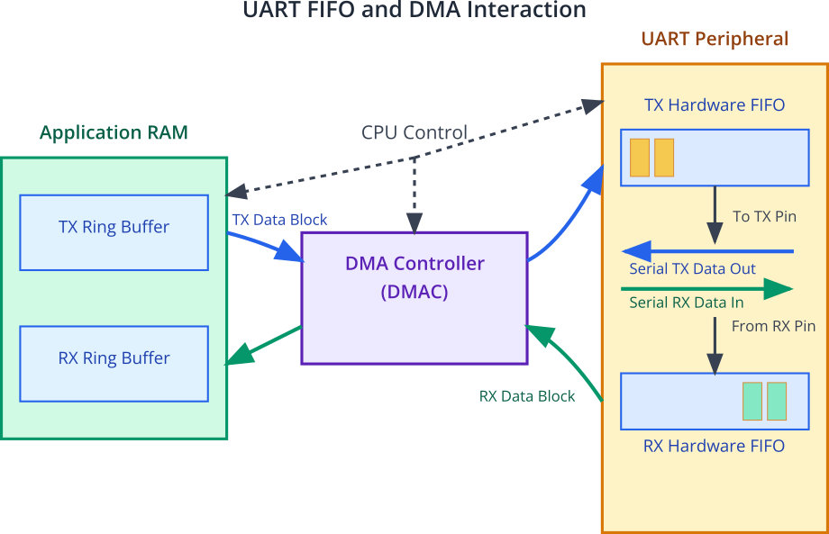
Data Flow for UART Transmission (TX) with DMA:
- The application prepares data in a RAM buffer.
- The CPU (via the UART driver) configures a DMA channel to transfer data from this RAM buffer to the UART’s Transmit FIFO (TX FIFO).
- The DMAC reads data from the RAM buffer and writes it into the UART TX FIFO.
- The UART peripheral automatically takes data from its TX FIFO and transmits it serially over the TX line.
- Once the DMA transfer is complete (all data moved from RAM to TX FIFO, or TX FIFO is continuously fed), the DMAC can notify the CPU.
flowchart TD
    A["Application prepares data<br>in RAM TX Buffer"] --> B{"CPU (via UART Driver)<br>Configures DMA Channel"};
    B -- "Params: RAM Addr, UART TX FIFO Addr, Size" --> C["DMAC Initiates Transfer"];
    C --> D["DMAC Reads Data<br>from RAM Buffer"];
    D --> E["DMAC Writes Data<br>to UART TX FIFO"];
    E --> F{"TX FIFO has data?"};
    F -- Yes --> G["UART Peripheral<br>transmits data serially<br>from TX FIFO over TX line"];
    G --> F;
    F -- No (or DMA block done) --> H{"DMA Transfer Complete?"};
    H -- Yes --> I["DMAC Notifies CPU<br>(e.g., Interrupt)"];
    I --> J["CPU Handles Completion<br>(e.g., free buffer, start next transfer)"];
    H -- No (more data in block) --> D;

    %% Styling
    classDef primary fill:#EDE9FE,stroke:#5B21B6,stroke-width:2px,color:#5B21B6;
    classDef process fill:#DBEAFE,stroke:#2563EB,stroke-width:1px,color:#1E40AF;
    classDef decision fill:#FEF3C7,stroke:#D97706,stroke-width:1px,color:#92400E;
    classDef success fill:#D1FAE5,stroke:#059669,stroke-width:2px,color:#065F46;

    class A,B,I,J primary;
    class C,D,E,G process;
    class F,H decision;
Data Flow for UART Reception (RX) with DMA:
- The UART peripheral receives serial data on its RX line and stores it in its Receive FIFO (RX FIFO).
- The CPU (via the UART driver) configures a DMA channel to transfer data from the UART RX FIFO to a designated RAM buffer.
- When data arrives in the RX FIFO (or a certain threshold is reached), the DMAC reads it from the RX FIFO and writes it into the RAM buffer.
- Once the DMA transfer is complete (e.g., buffer full or a specific amount of data transferred), the DMAC can notify the CPU.
flowchart TD
    A["UART Peripheral receives serial data<br>on RX line"] --> B["Data stored in UART RX FIFO"];
    B --> C{"CPU (via UART Driver)<br>Configures DMA Channel"};
    C -- "Params: UART RX FIFO Addr, RAM Addr, Size" --> D{"RX FIFO Threshold Reached<br>OR DMA Triggered"};
    D -- Yes --> E["DMAC Initiates Transfer"];
    E --> F["DMAC Reads Data<br>from UART RX FIFO"];
    F --> G["DMAC Writes Data<br>to RAM RX Buffer"];
    G --> H{"DMA Transfer Complete?<br>(e.g., buffer full, timeout)"};
    H -- Yes --> I["DMAC Notifies CPU<br>(e.g., Interrupt)"];
    I --> J["CPU Handles Completion<br>(e.g., process received data, prepare next buffer)"];
    H -- No (more space in buffer / expecting more data) --> D;

    %% Styling
    classDef primary fill:#EDE9FE,stroke:#5B21B6,stroke-width:2px,color:#5B21B6;
    classDef process fill:#DBEAFE,stroke:#2563EB,stroke-width:1px,color:#1E40AF;
    classDef decision fill:#FEF3C7,stroke:#D97706,stroke-width:1px,color:#92400E;
    classDef success fill:#D1FAE5,stroke:#059669,stroke-width:2px,color:#065F46;
    classDef check fill:#FEE2E2,stroke:#DC2626,stroke-width:1px,color:#991B1B;

    class A,B,F,G process;
    class C,I,J primary;
    class D,H decision;
    class E success;
Role of UART FIFOs:
UART peripherals have small hardware First-In-First-Out buffers (FIFOs) for both transmit and receive. These FIFOs act as a small temporary storage, decoupling the byte-by-byte serial transmission/reception from the block-oriented DMA transfers. DMA typically moves data in bursts to/from these FIFOs.
4. ESP-IDF UART Driver and DMA
A key point to understand when working with ESP-IDF is that the standard UART driver (driver/uart.h) often uses DMA implicitly (“under the hood”) when you configure it with transmit and receive buffers. Users typically do not need to manually configure DMA channels or descriptors for UART communication; the driver abstracts this complexity.
- Implicit DMA Usage via uart_driver_install():When you call uart_driver_install(uart_port_num, rx_buffer_size, tx_buffer_size, queue_size, &uart_queue, intr_alloc_flags), if rx_buffer_size and/or tx_buffer_size are non-zero, the driver allocates internal ring buffers of these sizes. The driver then uses the most efficient method available (which is often DMA, if supported by the hardware and enabled in Kconfig) to move data between these application-level ring buffers and the UART’s hardware FIFOs.
rx_buffer_size: Size of the ring buffer for incoming data. DMA will move data from the UART RX FIFO into this buffer.tx_buffer_size: Size of the ring buffer for outgoing data. If this is zero,uart_write_bytesmight block until all data is physically sent or copied to the TX FIFO. If non-zero,uart_write_bytescopies data to this TX ring buffer, and DMA (or interrupts) will handle sending it from this buffer to the TX FIFO.
- No Explicit “Enable DMA” API for UART: You won’t find a function like
uart_enable_dma()in the high-level UART driver API. The decision to use DMA is generally an internal optimization strategy of the driver based on the chip’s capabilities, Kconfig settings, and the buffer configuration you provide. - Driver Manages DMA Resources: The UART driver, when using DMA, is responsible for acquiring DMA channels, setting up DMA descriptors (if needed), and handling DMA completion interrupts. This simplifies UART usage for the application developer.
graph TD
    subgraph "User Application Layer"
        AppCode["Application Code<br>e.g., <b>uart_write_bytes()</b>,<br><b>uart_read_bytes()</b>"]
    end

    subgraph "ESP-IDF UART Driver Layer (Abstraction)"
        UARTDriver["ESP-IDF UART Driver<br>(driver/uart.h)"]
        RingBuffers["Manages TX/RX Ring Buffers"]
        DMASetup["Handles DMA Configuration<br>(Channels, Descriptors)"]
        InterruptHandling["Manages DMA/UART Interrupts"]
        UARTDriver --> RingBuffers
        UARTDriver --> DMASetup
        UARTDriver --> InterruptHandling
    end

    subgraph "Hardware Abstraction Layer (HAL) / Low-Level"
        DMAC["DMA Controller Hardware"]
        UARTHW["UART Peripheral Hardware"]
        TXFIFO["(TX FIFO)"]
        RXFIFO["(RX FIFO)"]
        UARTHW --> TXFIFO
        UARTHW --> RXFIFO
    end

    AppCode -- "API Calls" --> UARTDriver;

    RingBuffers -- "Data to/from for DMA" --> DMAC;
    DMASetup -- "Configures" --> DMAC;
    InterruptHandling -- "Responds to" --> DMAC;

    DMAC -- "Direct Memory Access" --> RingBuffers;
    DMAC -- "Moves data to/from" --> TXFIFO;
    DMAC -- "Moves data to/from" --> RXFIFO;

    InterruptHandling -- "Responds to" --> UARTHW;


    %% Styling
    classDef app fill:#FEF3C7,stroke:#D97706,stroke-width:1.5px,color:#92400E;
    classDef driver fill:#EDE9FE,stroke:#5B21B6,stroke-width:2px,color:#5B21B6;
    classDef driverInternal fill:#F3E8FF,stroke:#7C3AED,stroke-width:1px,color:#5B21B6;
    classDef hw fill:#DBEAFE,stroke:#2563EB,stroke-width:1.5px,color:#1E40AF;
    classDef hwInternal fill:#EFF6FF,stroke:#3B82F6,stroke-width:1px,color:#1E40AF;

    class AppCode app;
    class UARTDriver driver;
    class RingBuffers,DMASetup,InterruptHandling driverInternal;
    class DMAC,UARTHW hw;
    class TXFIFO,RXFIFO hwInternal;
- Kconfig Options: Certain Kconfig options related to DMA or specific peripherals might influence whether DMA is available or preferred for UART. However, for typical usage, the buffer sizes in
uart_driver_installare the primary user-facing controls that enable DMA-backed operation.
The functions uart_write_bytes() and uart_read_bytes() operate on these driver-managed ring buffers. If DMA is active:
uart_write_bytes(): Copies data from your application buffer to the TX ring buffer. DMA then asynchronously transfers this data from the TX ring buffer to the UART TX FIFO.uart_read_bytes(): Copies data from the RX ring buffer (which DMA has filled from the UART RX FIFO) to your application buffer.
Parameter in uart_driver_install() |
Description | Relevance to DMA |
|---|---|---|
uart_port_num |
UART port number (e.g., UART_NUM_0). |
Identifies the UART peripheral that will use DMA. |
rx_buffer_size |
Size of the internal ring buffer for incoming data (bytes). | If non-zero, the driver allocates this buffer. DMA is typically used to move data from the UART RX FIFO into this ring buffer. A larger size allows DMA to transfer more data before the application needs to read it. |
tx_buffer_size |
Size of the internal ring buffer for outgoing data (bytes). | If non-zero, uart_write_bytes() copies data here. DMA is then typically used to move data from this ring buffer to the UART TX FIFO. A larger size allows more data to be queued for DMA transmission. If 0, writes might be blocking and DMA usage for TX might be different or less efficient for asynchronous operations. |
queue_size |
Size of the UART event queue. Set to 0 if no event queue is needed. | Not directly for DMA data transfer, but can report events like UART_DATA, UART_FIFO_OVF, which are relevant when using DMA-backed buffers. |
&uart_queue |
Pointer to a FreeRTOS queue handle for UART events. | Used in conjunction with queue_size. |
intr_alloc_flags |
Flags for interrupt allocation. | DMA operations often conclude with an interrupt. These flags configure how that interrupt is handled. |
5. When is DMA Most Effective for UART?
While DMA is a powerful feature, its benefits are most pronounced in specific scenarios:
- High Baud Rates: At baud rates like 1 Mbps, 2 Mbps, or higher, the CPU might struggle to keep up with data using interrupts alone. DMA can handle these speeds much more efficiently.
- Large, Continuous Data Streams: When transmitting or receiving large files, long messages, or continuous sensor data, DMA significantly reduces the per-byte processing overhead.
- CPU-Intensive Applications: If your ESP32 application needs to perform complex calculations, manage other peripherals, or run network stacks concurrently, offloading UART data transfers to DMA frees up critical CPU resources.
- Real-time Constraints: For applications where consistent UART data flow with minimal jitter is important, DMA can provide more predictable transfer performance than interrupt-driven I/O, which can be affected by varying interrupt latencies and task scheduling.
| Scenario | Why DMA is Effective | Example Application |
|---|---|---|
| High Baud Rates | CPU struggles with interrupt overhead (per byte/few bytes) at speeds like 1 Mbps, 2 Mbps, or higher. DMA handles data bursts efficiently. | High-speed data logging, communication with fast peripherals (e.g., other MCUs, FPGAs), GPS modules outputting NMEA at high rates. |
| Large, Continuous Data Streams | DMA significantly reduces per-byte processing overhead when transmitting or receiving large files, long messages, or continuous sensor data. | Streaming audio or sensor data, firmware updates over UART, transferring large configuration files. |
| CPU-Intensive Applications | Offloading UART data transfers to DMA frees critical CPU resources for complex calculations, managing other peripherals, or running network stacks. | Applications running complex algorithms (e.g., DSP, AI inference) while also needing UART communication. IoT devices managing Wi-Fi/Bluetooth and sensor data via UART. |
| Real-time Constraints | DMA can provide more predictable transfer performance with minimal jitter compared to interrupt-driven I/O, which can be affected by varying interrupt latencies. | Industrial control systems, robotics, or any application where consistent UART data flow timing is crucial. |
| Power-Sensitive Applications (with Light Sleep) | Allows the CPU to enter light sleep modes while DMA continues to handle UART transfers in the background. | Battery-powered sensors that periodically transmit data and need to conserve power between transmissions. |
For very low baud rates and infrequent, small data packets, the overhead of setting up DMA might not provide a substantial benefit over simple interrupt-driven I/O, and the driver might internally opt for a simpler mechanism. However, the ESP-IDF driver is designed to choose an optimal strategy.
Practical Examples
The following examples will use the standard ESP-IDF UART driver. While we don’t explicitly “turn on” DMA, by providing appropriately sized TX and RX buffers to uart_driver_install(), we enable the driver to use DMA if it deems it efficient for the underlying hardware. The focus is on scenarios where DMA’s benefits (handling larger data chunks, higher speeds) become apparent.
Example 1: UART Echo at High Baud Rate (DMA-backed)
This example sets up a UART port to echo received data back to the sender at a high baud rate (e.g., 1 Mbps). The use of RX and TX buffers in uart_driver_install allows the driver to utilize DMA for efficient data handling.
Code (main/main.c):
#include <stdio.h>
#include <string.h>
#include "freertos/FreeRTOS.h"
#include "freertos/task.h"
#include "driver/uart.h"
#include "driver/gpio.h"
#include "esp_log.h"

#define UART_PORT_NUM      UART_NUM_1
#define UART_BAUD_RATE     1000000    // 1 Mbps
#define UART_RX_BUF_SIZE   (1024 * 2) // 2KB RX buffer
#define UART_TX_BUF_SIZE   (1024 * 2) // 2KB TX buffer (important for DMA to have space)

// Define UART pins (Change these to your desired pins)
#define UART_TXD_PIN  (GPIO_NUM_17)
#define UART_RXD_PIN  (GPIO_NUM_16)
#define UART_RTS_PIN  (UART_PIN_NO_CHANGE)
#define UART_CTS_PIN  (UART_PIN_NO_CHANGE)

static const char *TAG = "UART_DMA_ECHO";

static void uart_dma_echo_task(void *arg) {
    uint8_t *data = (uint8_t *) malloc(UART_RX_BUF_SIZE);
    if (data == NULL) {
        ESP_LOGE(TAG, "Failed to allocate memory for UART data buffer");
        vTaskDelete(NULL);
        return;
    }

    ESP_LOGI(TAG, "UART DMA echo task started. Baud: %d. Waiting for data...", UART_BAUD_RATE);

    while (1) {
        // Read data from the UART
        // The timeout helps prevent blocking indefinitely if no data arrives.
        int len = uart_read_bytes(UART_PORT_NUM, data, UART_RX_BUF_SIZE -1 , pdMS_TO_TICKS(100));

        if (len > 0) {
            data[len] = '\0'; // Null-terminate for logging if it's string data
            ESP_LOGI(TAG, "Received %d bytes. First few: %c%c%c...", len,
                     len > 0 ? data[0] : ' ',
                     len > 1 ? data[1] : ' ',
                     len > 2 ? data[2] : ' ');

            // Write data back to the UART
            int written = uart_write_bytes(UART_PORT_NUM, (const char *)data, len);
            if (written != len) {
                ESP_LOGW(TAG, "UART write error. Expected %d, wrote %d", len, written);
            } else {
                ESP_LOGI(TAG, "Echoed %d bytes.", written);
            }
        }
    }
    free(data);
    vTaskDelete(NULL);
}

void app_main(void) {
    uart_config_t uart_config = {
        .baud_rate = UART_BAUD_RATE,
        .data_bits = UART_DATA_8_BITS,
        .parity    = UART_PARITY_DISABLE,
        .stop_bits = UART_STOP_BITS_1,
        .flow_ctrl = UART_HW_FLOWCTRL_DISABLE, // Keep it simple, no flow control for this example
        .source_clk = UART_SCLK_DEFAULT,
    };

    ESP_LOGI(TAG, "Configuring UART%d for DMA-backed echo...", UART_PORT_NUM);

    // Install UART driver with sufficiently large RX and TX buffers.
    // This enables the driver to use DMA effectively.
    // No event queue for this simple echo example.
    ESP_ERROR_CHECK(uart_driver_install(UART_PORT_NUM, UART_RX_BUF_SIZE, UART_TX_BUF_SIZE, 0, NULL, 0));
    ESP_ERROR_CHECK(uart_param_config(UART_PORT_NUM, &uart_config));

    ESP_LOGI(TAG, "Setting UART%d pins: TXD=%d, RXD=%d", UART_PORT_NUM, UART_TXD_PIN, UART_RXD_PIN);
    ESP_ERROR_CHECK(uart_set_pin(UART_PORT_NUM, UART_TXD_PIN, UART_RXD_PIN, UART_RTS_PIN, UART_CTS_PIN));

    ESP_LOGI(TAG, "UART driver installed. DMA should be utilized by the driver for buffer transfers.");

    xTaskCreate(uart_dma_echo_task, "uart_dma_echo_task", 4096, NULL, 10, NULL); // Increased stack for logging
    ESP_LOGI(TAG, "UART DMA echo task created.");
}
Build Instructions:
- Save
main.c. - Build:
idf.py build
Run/Flash/Observe Steps:
- Hardware Connection: Connect ESP32 UART1 (TXD=GPIO17, RXD=GPIO16 in example) to a PC using a USB-to-Serial adapter capable of handling 1 Mbps (e.g., FT232RL based adapters usually work well). Ensure GND is connected.
- Flashing:
idf.py -p <YOUR_SERIAL_PORT> flash monitor - Observe:
- Open a serial terminal program (e.g., PuTTY, Tera Term, CoolTerm) connected to your USB-to-Serial adapter.
- Configure the terminal for 1000000 baud (1 Mbps), 8 data bits, no parity, 1 stop bit (8N1), and no flow control.
- Try sending larger blocks of text or a file through the serial terminal.
- Observe the ESP-IDF monitor for log messages indicating received and echoed data.
- You should see the data echoed back in your serial terminal. At 1 Mbps, DMA is crucial for the ESP32 to keep up without overwhelming the CPU. If DMA wasn’t being used effectively, you’d likely see data loss or very sluggish performance.
Example 2: High-Speed Continuous Data Transmission
This example demonstrates continuously transmitting a data pattern at a high baud rate. The TX buffer in uart_driver_install allows the UART driver to use DMA to feed the UART TX FIFO from this buffer.
Code (main/main.c):
#include <stdio.h>
#include <string.h>
#include "freertos/FreeRTOS.h"
#include "freertos/task.h"
#include "driver/uart.h"
#include "driver/gpio.h"
#include "esp_log.h"

#define UART_PORT_NUM      UART_NUM_1
#define UART_BAUD_RATE     2000000    // 2 Mbps
#define UART_TX_ONLY_BUF_SIZE (1024 * 4) // 4KB TX buffer
#define PACKET_SIZE        (1000)     // Size of packet to send repeatedly

#define UART_TXD_PIN  (GPIO_NUM_17)
#define UART_RXD_PIN  (GPIO_NUM_16) // Define RXD even if not actively used for TX only
#define UART_RTS_PIN  (UART_PIN_NO_CHANGE)
#define UART_CTS_PIN  (UART_PIN_NO_CHANGE)

static const char *TAG = "UART_DMA_TX_STREAM";
static uint8_t tx_packet[PACKET_SIZE];

static void uart_dma_tx_stream_task(void *arg) {
    // Initialize the packet with a pattern
    for (int i = 0; i < PACKET_SIZE; i++) {
        tx_packet[i] = (uint8_t)(i % 256);
    }

    ESP_LOGI(TAG, "UART DMA TX stream task started. Baud: %d. Sending %d byte packets...",
             UART_BAUD_RATE, PACKET_SIZE);

    uint64_t total_bytes_sent = 0;
    int64_t start_time = esp_timer_get_time();

    while (1) {
        int written = uart_write_bytes(UART_PORT_NUM, (const char *)tx_packet, PACKET_SIZE);

        if (written == PACKET_SIZE) {
            total_bytes_sent += written;
            // Optional: Log throughput periodically, not too often to affect performance
            if ((total_bytes_sent % (PACKET_SIZE * 100)) == 0) { // Log every 100 packets
                 int64_t current_time = esp_timer_get_time();
                 float duration_sec = (float)(current_time - start_time) / 1000000.0f;
                 float throughput_kbps = (float)(total_bytes_sent * 8) / (duration_sec * 1024.0f);
                 ESP_LOGI(TAG, "Total sent: %llu bytes. Throughput: %.2f Kbps", total_bytes_sent, throughput_kbps);
            }
        } else {
            ESP_LOGW(TAG, "UART write error or timeout. Expected %d, wrote %d. Retrying...", PACKET_SIZE, written);
            // The TX buffer might be full if uart_write_bytes doesn't write all.
            // A small delay can allow DMA to clear some buffer space.
            vTaskDelay(pdMS_TO_TICKS(10));
        }
        // No vTaskDelay here to push data as fast as possible, relying on uart_write_bytes blocking
        // or the TX buffer filling up to regulate flow.
        // If uart_write_bytes returns less than PACKET_SIZE, it means the TX buffer is full,
        // and it will block until space is available or timeout (if configured in uart_write_bytes_with_timeout).
        // For this example, uart_write_bytes will block if the TX buffer (UART_TX_ONLY_BUF_SIZE) is full.
    }
    vTaskDelete(NULL);
}

void app_main(void) {
    uart_config_t uart_config = {
        .baud_rate = UART_BAUD_RATE,
        .data_bits = UART_DATA_8_BITS,
        .parity    = UART_PARITY_DISABLE,
        .stop_bits = UART_STOP_BITS_1,
        .flow_ctrl = UART_HW_FLOWCTRL_DISABLE,
        .source_clk = UART_SCLK_DEFAULT,
    };

    ESP_LOGI(TAG, "Configuring UART%d for DMA-backed TX streaming...", UART_PORT_NUM);

    // Install UART driver with a large TX buffer, RX buffer size can be minimal if not used.
    ESP_ERROR_CHECK(uart_driver_install(UART_PORT_NUM, 256, UART_TX_ONLY_BUF_SIZE, 0, NULL, 0));
    ESP_ERROR_CHECK(uart_param_config(UART_PORT_NUM, &uart_config));

    ESP_LOGI(TAG, "Setting UART%d pins: TXD=%d", UART_PORT_NUM, UART_TXD_PIN);
    ESP_ERROR_CHECK(uart_set_pin(UART_PORT_NUM, UART_TXD_PIN, UART_RXD_PIN, UART_RTS_PIN, UART_CTS_PIN));

    ESP_LOGI(TAG, "UART driver installed. DMA will be used for TX buffer transfers.");

    xTaskCreate(uart_dma_tx_stream_task, "uart_dma_tx_stream_task", 4096, NULL, 10, NULL);
    ESP_LOGI(TAG, "UART DMA TX stream task created.");
}
Build and Run:
- Save, build, and flash.
- Hardware Connection: Connect ESP32 UART1 TXD (GPIO17) to the RXD of a receiving device (e.g., PC with USB-to-Serial adapter capable of 2 Mbps, or another microcontroller). Connect GND.
- Observe:
- Use a serial terminal or a custom receiver application on the PC capable of displaying or saving incoming data at 2 Mbps.
- Monitor the ESP-IDF log for throughput messages. You should see a high data rate.
- Note: Achieving sustained 2 Mbps without data loss on the receiving end can be challenging for some standard PC serial terminals. Specialized tools or a dedicated hardware receiver might be needed for verification. The ESP32 itself, with DMA, is capable of transmitting at this speed. The bottleneck is often the receiver or the USB-to-Serial adapter.
Variant Notes
The ESP32 family includes various System-on-Chips (SoCs), and their DMA capabilities can differ:
- ESP32 (Original): Features a DMA controller that can be used by peripherals like UART. It has a limited number of DMA channels shared among peripherals.
- ESP32-S2, ESP32-S3, ESP32-C3, ESP32-C6, ESP32-H2: These newer variants typically feature a more advanced GDMA (General DMA) controller. GDMA often offers more channels, more flexibility (e.g., linked list descriptors for scatter-gather operations), and potentially higher performance.
- Implicit DMA Usage: Regardless of the specific DMA controller type, the ESP-IDF UART driver aims to abstract these differences. When you enable TX/RX buffers via
uart_driver_install(), the driver utilizes the available DMA resources on the specific chip to handle data transfers between these buffers and the UART FIFOs. - Number of DMA Channels: The total number of available DMA channels is finite. If many peripherals are using DMA concurrently (e.g., SPI, I2S, ADC DMA, and UART DMA), there could be contention for channels on older chips with fewer DMA resources. Newer chips with GDMA usually have more channels, mitigating this. The UART driver requests a DMA channel when installed; if one isn’t available, it might fall back to interrupt-only operation or fail installation.
- Performance: While all support DMA for UART, the maximum sustained throughput without issues might vary slightly due to differences in CPU speed, memory architecture, and DMA controller efficiency. However, for most UART applications, the DMA capabilities of all ESP32 variants are generally sufficient for high baud rates.
| Feature | ESP32 (Original) | ESP32-S2 | ESP32-S3 | ESP32-C3 / C6 / H2 (Typical GDMA) |
|---|---|---|---|---|
| DMA Controller Type | DMA | DMA (sometimes referred to as GDMA-like features, but distinct from later GDMA) | GDMA (General DMA) | GDMA (General DMA) |
| Number of Channels | Limited (shared among peripherals, e.g., 2-4 usable by general peripherals depending on configuration) | More channels than original ESP32 (e.g., 4-5 pairs for TX/RX) | Multiple channels (e.g., 5 pairs for TX/RX) | Multiple channels (e.g., 3-5 pairs for TX/RX, varies by specific C/H chip) |
| Descriptor Support | Basic descriptor support. | Improved descriptor support, linked lists. | Advanced linked-list descriptors for scatter-gather operations. | Advanced linked-list descriptors for scatter-gather operations. |
| Flexibility | Moderate | Improved | High | High |
| Typical Max Throughput | Good, can handle high UART baud rates. | Improved, generally higher potential. | Very good, designed for high-speed peripheral data transfer. | Very good, efficient for various data transfer tasks. |
| ESP-IDF Driver Abstraction | The ESP-IDF UART driver aims to abstract these hardware differences. Users interact with uart_driver_install() and buffer configurations; the driver utilizes the underlying DMA/GDMA capabilities optimally. |
|||
Tip: The ESP-IDF documentation for the specific chip variant (components/hal/<target>/include/hal/dma_types.h or similar, and the TRM) provides details on the DMA controller if you need to delve deeper, but for UART, direct interaction is usually not required.
Common Mistakes & Troubleshooting Tips
| Mistake / Issue | Symptom(s) | Troubleshooting / Solution |
|---|---|---|
Insufficient Buffer Sizes in uart_driver_install() |
Data loss, UART_BUFFER_FULL or UART_FIFO_OVF events, uart_write_bytes() blocking or returning short writes. DMA effectiveness reduced. |
Increase rx_buffer_size and tx_buffer_size. Rule of thumb: at least 2x expected max packet size, or larger (e.g., 1024, 2048 bytes) for continuous streams. |
Misunderstanding uart_write_bytes() Blocking |
Application hangs or slows down during UART writes, even with a TX buffer. | Understand that uart_write_bytes() blocks if the TX ring buffer is full (default timeout portMAX_DELAY). Design logic accordingly, or use uart_tx_chars() / uart_write_bytes_with_timeout(). |
| Ignoring Return Values of UART functions | Silent failure to send all data; processing incomplete/incorrect received data. | Always check bytes written by uart_write_bytes() and bytes read by uart_read_bytes(). Handle discrepancies. |
| Receiver Not Keeping Up | Data loss/corruption on the receiving end, even if ESP32 reports successful TX. | Ensure receiver can handle the baud rate and data volume. Implement flow control (Chapter 136). Use appropriate high-speed capture tools on PC. |
| DMA and Low Power Modes (Deep Sleep) | UART communication stops/corrupts when entering/exiting deep sleep. | DMA context is usually lost in deep sleep. Re-initialize UART (and DMA via driver install) after waking. DMA typically works with light sleep. Check chip-specific power management docs. |
| Incorrect UART Pin Configuration | No data transmitted or received; garbage data. | Double-check uart_set_pin() arguments. Ensure physical connections match defined pins. Verify TX/RX are not swapped. |
| Baud Rate Mismatch | Garbled or no data on the receiving end. | Ensure both ESP32 and the connected device are configured for the exact same baud rate, data bits, parity, and stop bits. |
| Task Stack Overflow | Crashes or erratic behavior, especially when using logging (ESP_LOGI) or complex logic within the UART task. |
Increase stack size for the UART handling task in xTaskCreate(). Monitor stack high water mark if possible. |
Exercises
- Throughput Measurement:
- Modify “Example 2: High-Speed Continuous Data Transmission.”
- Implement a mechanism on a receiving device (e.g., another ESP32 or a PC program) to accurately count the number of bytes received over a fixed period (e.g., 10 seconds).
- Experiment with different baud rates (e.g., 1 Mbps, 1.5 Mbps, 2 Mbps) and
PACKET_SIZE. - Calculate and compare the actual throughput achieved. Observe if the ESP32’s TX buffer size in
uart_driver_installinfluences this. - Goal: Understand the practical limits and factors affecting high-speed UART DMA transfers.
- DMA-backed Bidirectional Data Exchange:
- Set up two ESP32 boards.
- Configure UART1 on both boards for a high baud rate (e.g., 1 Mbps) with reasonably sized RX and TX buffers for DMA.
- Board A: Periodically sends a data packet (e.g., 512 bytes with a sequence number and a small payload) to Board B.
- Board B: Receives the packet, verifies the sequence number, and sends an acknowledgment packet (e.g., 64 bytes) back to Board A.
- Board A: Receives and verifies the acknowledgment.
- Log any errors, timeouts, or sequence number mismatches on both boards.
- Goal: Create a robust, high-speed, bidirectional communication link leveraging DMA on both ends.
- CPU Load Observation (Conceptual):
- Take “Example 1: UART Echo at High Baud Rate.”
- Add a separate FreeRTOS task that performs a computationally intensive loop (e.g., calculating a large number of prime numbers or a complex mathematical function) and periodically prints its progress or a “heartbeat” message to the console (UART0).
- Run the UART echo on UART1 at a high baud rate (1 Mbps) and send a continuous stream of data to it.
- Observe the responsiveness and progress of the computationally intensive task.
- Then, significantly reduce the
UART_RX_BUF_SIZEandUART_TX_BUF_SIZEfor UART1 (e.g., to 64 bytes) or try to force a more interrupt-heavy mode (if possible through Kconfig, though harder with the standard driver). - Again, send a continuous stream to UART1 and observe the impact on the computationally intensive task.
- Goal: Conceptually understand how offloading UART to DMA can free up CPU resources for other tasks. (Actual CPU load measurement tools would be needed for precise numbers, but qualitative observation can be insightful).
Summary
- DMA (Direct Memory Access) allows peripherals to transfer data to/from RAM without direct CPU involvement, significantly reducing CPU load.
- The ESP-IDF UART driver implicitly uses DMA when TX and RX buffers are configured in
uart_driver_install(), especially for ESP32 variants with capable DMA controllers. - Benefits of UART with DMA include higher throughput, reduced CPU intervention, and freeing the CPU for other application tasks.
- DMA is most effective for high baud rates and large/continuous data streams.
- Proper buffer sizing in
uart_driver_install()is crucial for efficient DMA operation. - Newer ESP32 variants (S2, S3, C-series, H-series) feature more advanced GDMA controllers, offering more channels and flexibility.
- While DMA operation is largely abstracted by the UART driver, understanding its presence helps in designing high-performance serial communication and troubleshooting.
Further Reading
- ESP-IDF UART Driver Documentation: (Already provided in previous chapters, but always relevant)
- ESP-IDF DMA Controller Documentation (General):
- While you don’t typically use this directly for UART, understanding the underlying DMA capabilities can be useful. Search for “DMA Controller” or “GDMA Controller” in the ESP-IDF documentation or the Technical Reference Manual (TRM) for your specific ESP32 variant.
- Example (ESP32-S3 TRM): The Technical Reference Manual for the ESP32-S3 will have a dedicated chapter on its GDMA controller.
- Application Notes on High-Speed Data Transfer: Search Espressif’s website for application notes related to data streaming or DMA usage.
