
Chapter 19: ESP32 Power Modes and Management
Chapter Objectives
- Understand the importance of power management in embedded systems, especially battery-powered ones.
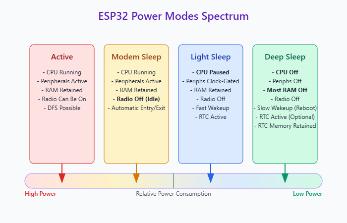
- Learn about the different power modes available on ESP32: Active, Modem Sleep, Light Sleep, Deep Sleep.
- Understand the role of the Real-Time Clock (RTC) controller and RTC peripherals in low-power operation.
- Configure various wakeup sources: Timer, GPIO, Touch Pad, UART, etc.
- Implement manual entry into Light Sleep and Deep Sleep modes using ESP-IDF APIs.
- Learn how to retain data across Deep Sleep cycles using RTC memory.
- Understand and configure the ESP-IDF Power Management system for automatic Light Sleep and Dynamic Frequency Scaling (DFS).
- Use power management locks (
esp_pm_lock) to control automatic power-saving behavior. - Recognize the differences in power modes and features across various ESP32 variants.
- Identify and troubleshoot common power management issues.
Introduction
One of the most significant advantages of the ESP32 platform is its suitability for battery-powered IoT applications. However, achieving long battery life requires careful management of power consumption. Microcontrollers consume the most power when their CPU cores and peripherals are fully active. By strategically placing the chip into low-power sleep modes when idle and only waking it up when necessary, we can dramatically reduce the average power consumption and extend battery life from hours to potentially months or even years, depending on the application’s duty cycle.
The ESP32 family offers several power modes, ranging from fully active to deep sleep states where most of the chip is powered down. Transitioning between these states, retaining essential data during sleep, and configuring appropriate wakeup triggers are fundamental skills for developing power-efficient applications.
This chapter explores the different power modes available in ESP-IDF v5.x, the underlying hardware mechanisms involving the RTC (Real-Time Clock) controller, and the APIs used to manage power states and configure wakeup sources. We will cover both manual sleep invocation and the automated power management features provided by ESP-IDF.
Theory
Power Consumption Basics
In an embedded system like the ESP32, power consumption is primarily driven by:
- CPU Core Activity: Running instructions consumes significant power. Higher clock frequencies generally mean higher power consumption.
- Peripheral Activity: Active peripherals (WiFi, Bluetooth, SPI, I2C, timers, etc.) draw power.
- Memory Access: Reading from and writing to memory (Flash, RAM, RTC memory) consumes power.
- Radio Transceivers (WiFi/Bluetooth): Transmitting and receiving data are among the most power-intensive operations.
- Static Leakage: Even when idle, transistors leak a small amount of current, contributing to static power consumption. This becomes more significant in very low-power modes.
Power management aims to minimize these factors by slowing down clocks, disabling unused peripherals, and powering down parts of the chip when they are not needed.
ESP32 Power Modes
ESP-IDF defines several primary power modes:
| Power Mode | CPU State | RAM State | Digital Peripherals | Radio (WiFi/BT) | RTC Domain | Wakeup | Power Consumption |
|---|---|---|---|---|---|---|---|
| Active | Running (Frequency may vary with DFS) | Active / Retained | Active / Clocked | Can be Active | Active | N/A (Already awake) | Highest |
| Modem Sleep | Running | Active / Retained | Active / Clocked | Radio/Baseband Off (when idle but associated) | Active | Radio activity (TX/RX), other interrupts | Medium-High (depends on radio config/activity) |
| Light Sleep | Paused (Clock Gated) | Retained | Clock Gated (potentially Power Gated) | Off | Active | Fast (CPU resumes execution), requires specific trigger (Timer, GPIO, UART, Touch, etc.) | Low |
| Deep Sleep | Powered Down | Most RAM Powered Down (Lost) | Powered Down | Off | Active (Controller, Peripherals, RTC Memory optional) | Slow (Full Reboot), requires specific RTC trigger (Timer, RTC GPIO, Touch, ULP, etc.) | Lowest |
- Active Mode:
- CPU cores and all configured peripherals are active and running.
- Radio transceivers (WiFi/Bluetooth) can be enabled and operating.
- Highest power consumption state.
- The CPU clock speed can often be adjusted dynamically (Dynamic Frequency Scaling – DFS) to save power even within Active mode.
- Modem Sleep Mode:
- CPUs are operational, and peripherals are active.
- The WiFi/Bluetooth baseband and radio sections are powered down when not actively transmitting or receiving.
- This mode is automatically entered by the WiFi/Bluetooth drivers when the radios are idle but still associated (e.g., connected to a WiFi AP).
- Provides significant power savings compared to Active mode if radio usage is intermittent, without requiring explicit entry/exit by the application firmware for the sleep itself (though radio usage patterns dictate it).
- Power consumption depends heavily on the WiFi/Bluetooth configuration (e.g., DTIM interval for WiFi).
- Light Sleep Mode:
- CPU cores are paused (
clk_cpuis gated). - Digital peripherals are clock-gated, potentially power-gated depending on configuration.
- Most RAM and peripheral state are retained.
- The RTC controller and RTC peripherals remain active.
- Wakeup is fast as the CPU resumes execution from where it left off without a full reboot.
- Requires an explicit wakeup trigger (Timer, GPIO, UART, Touch Pad, etc.).
- Offers moderate power savings.
- CPU cores are paused (
- Deep Sleep Mode:
- CPU cores are powered down.
- Most RAM is powered down (contents lost).
- Digital peripherals are powered down.
- Main system clock is off.
- Only the RTC controller, RTC peripherals (like Timer, some GPIOs), and RTC memory remain powered (optionally).
- Lowest power consumption state.
- Wakeup causes a full system reboot. Execution does not resume from where it left off; the chip starts executing from the bootloader.
- State must be explicitly saved to RTC memory or external non-volatile storage if it needs to be preserved across deep sleep cycles.
- Requires an explicit wakeup trigger configured via the RTC controller.
The RTC (Real-Time Clock) Domain
The RTC controller and its associated peripherals and memory form a separate power domain that can remain powered even when the main digital core (CPU, most peripherals, main RAM) is in Light or Deep Sleep. This is crucial for low-power operation:
| Component | Role in Low Power Modes (Light/Deep Sleep) | Key ESP-IDF Attribute/Notes |
|---|---|---|
| RTC Controller | Manages entry into sleep modes, configures and monitors wakeup sources, controls power gating of other domains. Remains active. | Core logic for esp_sleep functions. |
| RTC Timers | Can remain active and trigger a wakeup after a specified duration. | Used by esp_sleep_enable_timer_wakeup(). |
| RTC GPIOs | Specific GPIO pins that can remain active and trigger wakeup based on input level or edge changes during sleep. | Requires initialization via rtc_gpio_... functions. Used by esp_sleep_enable_gpio_wakeup(), esp_sleep_enable_ext0_wakeup(), esp_sleep_enable_ext1_wakeup(). Check datasheet for which pins are RTC capable. |
| RTC Memory (Slow & Fast) | Small blocks of SRAM within the RTC domain that retain their contents during Deep Sleep. Essential for preserving state across reboots caused by deep sleep wakeup. | RTC_DATA_ATTR / RTC_SLOW_ATTR (Slow RAM), RTC_FAST_ATTR (Fast RAM). Availability/size varies by chip. |
| ULP Co-processor (if available) | A simple, low-power co-processor that can run independently while main CPUs are in Deep Sleep. Can perform basic tasks (sensor reads) and trigger wakeup based on conditions. | Requires specific ULP toolchain and programming. Wakeup via esp_sleep_enable_ulp_wakeup(). |
| RTC Peripherals (subset) | Some peripherals might have RTC domain components allowing limited functionality or wakeup capability (e.g., Touch Pad sensor). | Specific wakeup functions like esp_sleep_enable_touchpad_wakeup(). Check documentation for peripheral-specific low-power features. |
- RTC Controller: Manages sleep modes and wakeup triggers.
- RTC Timers: Can be configured to wake the system after a specific duration.
- RTC GPIOs: Certain GPIO pins can be configured to trigger wakeup on level or edge changes even during sleep (requires RTC IO MUX).
- RTC Memory: Small amounts of static RAM (Fast and Slow) within the RTC domain retain their contents during Deep Sleep. This is essential for storing state information needed after wakeup.
RTC_DATA_ATTR: Variables marked with this attribute are placed in RTC “slow” memory (accessible by main CPU). Contents persist during Deep Sleep.RTC_SLOW_ATTR: Synonym forRTC_DATA_ATTR.RTC_FAST_ATTR: Variables marked with this are placed in RTC “fast” memory. Contents persist during Deep Sleep. Faster access than slow memory. (Availability and size vary by chip).RTC_BSS_ATTR: For zero-initialized data in RTC memory.
- ULP (Ultra Low Power) Co-processor (on some variants): A simple co-processor within the RTC domain that can perform basic tasks (like sensor readings) while the main CPUs are in Deep Sleep, potentially waking them only when a specific condition is met.
Wakeup Sources
To exit Light or Deep Sleep modes, one or more wakeup sources must be configured before entering sleep. Common sources include:
| Wakeup Source | ESP-IDF Enable Function (esp_sleep.h) |
Description | Typical Sleep Mode(s) |
|---|---|---|---|
| Timer | esp_sleep_enable_timer_wakeup(uint64_t time_in_us) |
Wakes up after a specified time interval (microseconds) using the RTC timer. | Light Sleep, Deep Sleep |
| GPIO (Single/Multiple, RTC IO) | esp_deep_sleep_enable_gpio_wakeup(uint64_t gpio_pin_mask, esp_gpio_wakeup_level_t level) (v5.x+) — esp_sleep_enable_ext0_wakeup(gpio_num_t gpio_num, int level) — esp_sleep_enable_ext1_wakeup(uint64_t mask, esp_sleep_ext1_wakeup_mode_t mode) |
Wakes up on level/edge change on specific RTC-capable GPIOs. ext0 for single pin level, ext1 for multiple pins (wake on any high / all low), gpio_wakeup for specific level on multiple pins. Requires rtc_gpio_init. |
Deep Sleep (Requires RTC IOs), Light Sleep |
| GPIO (Light Sleep Only) | esp_sleep_enable_gpio_wakeup() |
Wakes from Light Sleep using potentially non-RTC GPIOs (if configured via CONFIG_GPIO_WAKEUP_LIGHT_SLEEP). Configuration done via standard gpio_config and gpio_wakeup_enable. |
Light Sleep Only |
| Touch Pad | esp_sleep_enable_touchpad_wakeup() |
Wakes up when a configured touch pad sensor detects a change in capacitance. Requires touch peripheral initialization. | Light Sleep, Deep Sleep (on variants with Touch Sensor) |
| UART | esp_sleep_enable_uart_wakeup(int uart_num) |
Wakes up after detecting a configured number of edges on the UART RX pin (indicating incoming data). Threshold configured via uart_set_wakeup_threshold(). |
Light Sleep (Check variant/config support) |
| ULP Co-processor | esp_sleep_enable_ulp_wakeup() |
Wakes up the main CPU based on logic executed by the Ultra Low Power co-processor. | Deep Sleep (on variants with ULP) |
Note: Availability of wakeup sources and specific function behavior can vary by ESP32 variant and ESP-IDF version. Always check the API documentation for your target. Use esp_sleep_get_wakeup_cause() after waking to determine the trigger.
- Timer (
esp_sleep_enable_timer_wakeup): Wakes the chip after a specified time interval (microseconds). Managed by the RTC timer. - GPIO (
esp_sleep_enable_gpio_wakeup,gpio_wakeup_enable): Wakes the chip on a specific edge or level detected on one or more RTC-capable GPIO pins.- Deep Sleep: Requires specific RTC GPIOs.
- Light Sleep: Can often use more GPIOs, depending on configuration (
CONFIG_GPIO_WAKEUP_LIGHT_SLEEP).
- Touch Pad (
esp_sleep_enable_touchpad_wakeup): Wakes the chip when a capacitance change is detected on a configured touch input pin (available on variants with touch peripherals). - UART (
esp_sleep_enable_uart_wakeup): Wakes the chip when a certain number of edges are detected on the UART RX pin (useful for waking on incoming data). Only available for Light Sleep on many variants. Checkmenuconfig->Component config->Power Management->Enable UART wakeup from light sleep. - ULP Co-processor (
esp_sleep_enable_ulp_wakeup): Wakes the main CPUs based on a condition detected by the ULP program (variants with ULP only). - External (
esp_sleep_enable_ext0_wakeup,esp_sleep_enable_ext1_wakeup): Specific mechanisms using RTC GPIOs, often allowing wakeup based on multiple pins (e.g., wake if any selected GPIO is high, or if all selected GPIOs are low).ext1often allows more pins thanext0. - GPIO (Light Sleep Only –
esp_sleep_enable_gpio_wakeup): Allows waking from Light Sleep using potentially non-RTC GPIOs if configured.
After waking up, you can determine the cause using esp_sleep_get_wakeup_cause().
Manual Sleep Invocation (esp_sleep.h)
The esp_sleep.h header provides functions to manually enter sleep modes:
- Configure Wakeup Source(s): Call one or more
esp_sleep_enable_..._wakeup()functions. - Enter Sleep:
esp_light_sleep_start(): Enters Light Sleep. Execution resumes from this point after wakeup.esp_deep_sleep_start(): Enters Deep Sleep. The chip reboots upon wakeup. This function does not return.
graph TD
    A["Application Running (Active Mode)"] --> B{Need to Enter Sleep?};
    B -- Yes --> C("Configure Wakeup Source(s)<br>e.g., esp_sleep_enable_timer_wakeup()");
    C --> D(Optional: Disable Peripherals / Reduce Freq);
    D --> E{Choose Sleep Mode};
    E -- Light Sleep --> F["Call esp_light_sleep_start()"];
    E -- Deep Sleep --> G["Call esp_deep_sleep_start()"];

    subgraph "Wakeup Process"
        F -- Wakeup Trigger Occurs --> H["Execution Resumes After esp_light_sleep_start()"];
        G -- Wakeup Trigger Occurs --> I[System Reboots];
    end

    H --> J(Optional: Restore Peripherals / Freq);
    J --> K[Application Continues];

    I --> L[Bootloader Runs -> Application Starts from Beginning];
    L --> M("Check esp_sleep_get_wakeup_cause()");
    M --> N(Retrieve State from RTC Memory if needed);
    N --> K;

    B -- No --> A;
    K --> A;

    %% Styling
    classDef startNode fill:#EDE9FE,stroke:#5B21B6,stroke-width:2px,color:#5B21B6;
    classDef processNode fill:#DBEAFE,stroke:#2563EB,stroke-width:1px,color:#1E40AF;
    classDef decisionNode fill:#FEF3C7,stroke:#D97706,stroke-width:1px,color:#92400E;
    classDef sleepNode fill:#A78BFA,stroke:#5B21B6,stroke-width:1px,color:#FFFFFF;
    classDef rebootNode fill:#FEE2E2,stroke:#DC2626,stroke-width:1px,color:#991B1B;
    classDef resumeNode fill:#D1FAE5,stroke:#059669,stroke-width:1px,color:#065F46;

    class A,K processNode;
    class B,E decisionNode;
    class C,D,J,M,N processNode;
    class F,G sleepNode;
    class H resumeNode;
    class I,L rebootNode;
Tip: Before entering Deep Sleep, ensure any necessary data is saved to RTC memory or external non-volatile storage. Also, consider disabling peripherals and WiFi/Bluetooth gracefully to minimize wakeup time or potential issues.
Automatic Power Management (esp_pm.h)
ESP-IDF includes a power management framework that can automatically manage transitions between Active and Light Sleep modes, and also perform Dynamic Frequency Scaling (DFS).
Enabling: Set CONFIG_PM_ENABLE in menuconfig (Component config -> Power Management).
Configuration (esp_pm_config_esp32_t, etc.): Define minimum/maximum CPU frequencies and whether automatic Light Sleep is enabled.
esp_pm_config_t pm_config = {
    .max_freq_mhz = CONFIG_EXAMPLE_MAX_CPU_FREQ_MHZ, // e.g., 160, 240
    .min_freq_mhz = CONFIG_EXAMPLE_MIN_CPU_FREQ_MHZ, // e.g., 10, 40, 80
    .light_sleep_enable = true // Enable automatic light sleep
};
esp_err_t err = esp_pm_configure(&pm_config);
How it Works: When enabled, the RTOS vApplicationIdleHook (executed by idle tasks when no other tasks are ready) checks if Light Sleep can be entered based on configured wakeup sources and active power management locks. If DFS is enabled, the CPU frequency might be lowered when idle or under light load.
Power Management Locks (esp_pm_lock): Crucial for controlling automatic behavior. Peripherals or application logic can acquire locks to prevent unwanted state changes:
Lock Type (esp_pm_lock_type_t) |
Effect When Acquired | Common Use Case | Management Functions |
|---|---|---|---|
ESP_PM_CPU_FREQ_MAX |
Prevents the automatic power management system (DFS) from lowering the CPU frequency below the maximum configured frequency (pm_config.max_freq_mhz). |
Acquired before performance-critical code sections (e.g., complex calculations, signal processing) to ensure maximum CPU speed. Released afterwards. | esp_pm_lock_create()esp_pm_lock_acquire()esp_pm_lock_release()esp_pm_lock_delete() |
ESP_PM_APB_FREQ_MAX |
Prevents DFS from lowering the APB bus frequency below its maximum. The APB frequency is often tied to the CPU frequency, so this lock usually has a similar effect to ESP_PM_CPU_FREQ_MAX regarding CPU speed. |
Used by peripherals that require the maximum APB bus speed for correct operation or timing. Often acquired/released by peripheral drivers internally. | |
ESP_PM_NO_LIGHT_SLEEP |
Prevents the automatic power management system from entering Light Sleep mode, even if the system is idle and Light Sleep is enabled in the configuration. | Acquired by tasks or drivers that require the CPU and peripherals to remain active continuously, even during idle periods (e.g., continuous data sampling, certain communication protocols). |
Usage:
- Create a lock:
esp_pm_lock_create(type, arg, name, &handle); - Acquire the lock when needed:
esp_pm_lock_acquire(handle); - Release the lock when the constraint is no longer needed:
esp_pm_lock_release(handle); - Delete the lock when finished:
esp_pm_lock_delete(handle);
Example: A task performing a time-critical calculation might acquire an ESP_PM_CPU_FREQ_MAX lock beforehand and release it afterward. A driver managing continuous SPI communication might acquire an ESP_PM_NO_LIGHT_SLEEP lock.
%%{init: {'theme': 'base'}}%%
flowchart TD
    Start([System Running]) --> IdleTask[Idle Task Running]
    IdleTask --> CheckLocks{Check PM Locks}

    CheckLocks -->|"PM locks active"| IdleTask
    CheckLocks -->|"No PM locks"| CheckSleep{Sleep Permitted?}

    CheckSleep -->|"No"| IdleTask
    CheckSleep -->|"Yes"| PrepSleep[Prepare for Sleep]

    PrepSleep --> LightSleep[Enter Light Sleep Mode]
    LightSleep --> Wakeup[Handle Wakeup Event]

    Wakeup --> TaskReady{Higher priority\ntask ready?}
    TaskReady -->|"No"| IdleTask
    TaskReady -->|"Yes"| OtherTask[Higher Priority Task Running]

    OtherTask --> IdleTask

    %% Styling
    classDef default fill:#f9f9f9,stroke:#333,stroke-width:1px
    classDef process fill:#DBEAFE,stroke:#2563EB,stroke-width:1px
    classDef decision fill:#FEF3C7,stroke:#D97706,stroke-width:1px
    classDef sleep fill:#F5F3FF,stroke:#6D28D9,stroke-width:2px
    classDef startend fill:#EDE9FE,stroke:#5B21B6,stroke-width:2px

    class Start,OtherTask startend
    class IdleTask,PrepSleep,Wakeup process
    class CheckLocks,CheckSleep,TaskReady decision
    class LightSleep sleep
Practical Examples
Project Setup:
Follow the standard project setup (copy hello_world, open in VS Code).
Common Includes and Setup:
Add/ensure these includes are at the top of your main/your_main_file.c:
#include <stdio.h>
#include <string.h>
#include <time.h> // For time functions
#include "freertos/FreeRTOS.h"
#include "freertos/task.h"
#include "esp_sleep.h"
#include "esp_log.h"
#include "driver/rtc_io.h" // For RTC GPIO functions
#include "driver/gpio.h"   // For regular GPIO config
#include "esp_pm.h"        // For Power Management config/locks

static const char *TAG = "PWR_MGMT_EXAMPLE";

// Define a GPIO for wakeup (ensure it's RTC capable for deep sleep)
// Check ESP32 datasheet for RTC GPIOs (e.g., GPIO 0, 2, 4, 12-15, 25-27, 32-39 for original ESP32)
#define WAKEUP_GPIO GPIO_NUM_4
Example 1: Manual Light Sleep with Timer Wakeup
This example enters Light Sleep for 5 seconds and then wakes up.
void app_main(void) {
    ESP_LOGI(TAG, "Starting Manual Light Sleep Example...");

    // Configure wakeup timer
    const int wakeup_time_sec = 5;
    ESP_LOGI(TAG, "Enabling timer wakeup to wake up in %d seconds", wakeup_time_sec);
    esp_sleep_enable_timer_wakeup(wakeup_time_sec * 1000000); // Time in microseconds

    // --- Optional: Disable peripherals before sleep ---
    // Example: If WiFi/BT were active, disable them:
    // esp_bluedroid_disable();
    // esp_bt_controller_disable();
    // esp_wifi_stop();
    // ESP_LOGI(TAG, "Peripherals disabled (example)");

    // --- Optional: Reduce CPU frequency before light sleep ---
    // rtc_clk_cpu_freq_set(RTC_CPU_FREQ_XTAL); // Switch to XTAL frequency
    // ESP_LOGI(TAG, "CPU frequency reduced (example)");

    ESP_LOGI(TAG, "Entering light sleep now...");
    // Add a small delay to ensure log message is printed before sleep
    vTaskDelay(pdMS_TO_TICKS(100));

    // --- Enter Light Sleep ---
    esp_err_t err = esp_light_sleep_start();

    // --- Execution resumes here after wakeup ---
    if (err == ESP_OK) {
        esp_sleep_wakeup_cause_t cause = esp_sleep_get_wakeup_cause();
        ESP_LOGI(TAG, "Woke up from light sleep! Wakeup cause: %d", cause);
        if (cause == ESP_SLEEP_WAKEUP_TIMER) {
            ESP_LOGI(TAG, "Woken up by timer.");
        } else {
            ESP_LOGI(TAG, "Woken up by unexpected source: %d", cause);
        }
    } else {
        ESP_LOGE(TAG, "Failed to enter light sleep: %s", esp_err_to_name(err));
    }

    // --- Optional: Restore CPU frequency and re-enable peripherals ---
    // Example: Restore frequency if it was changed
    // rtc_clk_cpu_freq_set(RTC_CPU_FREQ_DEFAULT); // Restore configured frequency
    // Example: Re-enable peripherals if needed
    // esp_wifi_start(); // etc.

    ESP_LOGI(TAG, "Light Sleep Example Finished. Restarting in 5s...");
    vTaskDelay(pdMS_TO_TICKS(5000));
    esp_restart(); // Restart to run again
}
Build, Flash, and Monitor:
Standard procedure.
Expected Output:
The device will print the initial messages, indicate it’s entering Light Sleep, and then approximately 5 seconds later, it will print the wakeup messages and restart.
I (XXX) PWR_MGMT_EXAMPLE: Starting Manual Light Sleep Example...
I (XXX) PWR_MGMT_EXAMPLE: Enabling timer wakeup to wake up in 5 seconds
I (XXX) PWR_MGMT_EXAMPLE: Entering light sleep now...
I (XXX) PWR_MGMT_EXAMPLE: Woke up from light sleep! Wakeup cause: 2 // Cause 2 is Timer
I (XXX) PWR_MGMT_EXAMPLE: Woken up by timer.
I (XXX) PWR_MGMT_EXAMPLE: Light Sleep Example Finished. Restarting in 5s...
// --- Device Resets ---
ets Jun  8 2016 00:22:57...
...
I (XXX) PWR_MGMT_EXAMPLE: Starting Manual Light Sleep Example...
...
Example 2: Manual Deep Sleep with GPIO Wakeup & RTC Memory
This example enters Deep Sleep and uses RTC memory to count resets. It wakes up when WAKEUP_GPIO is pulled low (assuming a button connected to GND with internal pull-up enabled).
// Variable placed in RTC memory - persists across deep sleep
RTC_DATA_ATTR static int boot_count = 0;

void app_main(void) {
    // Increment boot count
    boot_count++;
    ESP_LOGI(TAG, "Starting Manual Deep Sleep Example...");
    ESP_LOGI(TAG, "Boot count: %d", boot_count);

    // Check wakeup cause
    esp_sleep_wakeup_cause_t cause = esp_sleep_get_wakeup_cause();
    if (cause != ESP_SLEEP_WAKEUP_UNDEFINED) { // Skip first boot
        ESP_LOGI(TAG, "Wakeup cause: %d", cause);
        if (cause == ESP_SLEEP_WAKEUP_GPIO || cause == ESP_SLEEP_WAKEUP_EXT0 || cause == ESP_SLEEP_WAKEUP_EXT1) {
            ESP_LOGI(TAG, "Woken up by GPIO.");
            // Could check which GPIO triggered if using ext1
        } else {
             ESP_LOGI(TAG, "Woken up by other source: %d", cause);
        }
    } else {
        ESP_LOGI(TAG, "First boot or not woken from deep sleep.");
    }

    // Configure GPIO wakeup
    ESP_LOGI(TAG, "Enabling GPIO wakeup on GPIO %d (LOW level)", WAKEUP_GPIO);
    // Ensure the selected GPIO is RTC capable
    if (!rtc_gpio_is_valid_gpio(WAKEUP_GPIO)) {
        ESP_LOGE(TAG, "GPIO %d is not an RTC IO!", WAKEUP_GPIO);
    } else {
        // Initialize RTC GPIO, enable input, enable pull-up
        rtc_gpio_init(WAKEUP_GPIO);
        rtc_gpio_set_direction(WAKEUP_GPIO, RTC_GPIO_MODE_INPUT_ONLY);
        rtc_gpio_pullup_en(WAKEUP_GPIO);
        rtc_gpio_pulldown_dis(WAKEUP_GPIO); // Disable pulldown

        // Configure wakeup - wake up when GPIO is LOW (level 0)
        // Use esp_deep_sleep_enable_gpio_wakeup for ESP-IDF v5.x+
        // Note: esp_sleep_enable_ext0_wakeup is also an option for single GPIO on level
        esp_deep_sleep_enable_gpio_wakeup((1ULL << WAKEUP_GPIO), ESP_GPIO_WAKEUP_GPIO_LOW);
        // Or use ext0: esp_sleep_enable_ext0_wakeup(WAKEUP_GPIO, 0); // 0 for LOW level

        ESP_LOGI(TAG, "RTC GPIO %d configured for wakeup.", WAKEUP_GPIO);
    }


    ESP_LOGI(TAG, "Entering deep sleep now. Press button on GPIO %d to wake up...", WAKEUP_GPIO);
    // Add a small delay to ensure log message is printed before sleep
    vTaskDelay(pdMS_TO_TICKS(200));

    // --- Enter Deep Sleep ---
    esp_deep_sleep_start(); // This function does not return
}
Build, Flash, and Monitor:
Standard procedure. Connect a button between WAKEUP_GPIO and GND.
Expected Output:
On the first boot, it will print Boot count: 1. Then it enters deep sleep. When you press the button (pulling WAKEUP_GPIO low), the device will reboot, print Boot count: 2, indicate it was woken by GPIO, and re-enter deep sleep. The boot count persists across reboots because it’s in RTC memory.
I (XXX) PWR_MGMT_EXAMPLE: Starting Manual Deep Sleep Example...
I (XXX) PWR_MGMT_EXAMPLE: Boot count: 1
I (XXX) PWR_MGMT_EXAMPLE: First boot or not woken from deep sleep.
I (XXX) PWR_MGMT_EXAMPLE: Enabling GPIO wakeup on GPIO 4 (LOW level)
I (XXX) PWR_MGMT_EXAMPLE: RTC GPIO 4 configured for wakeup.
I (XXX) PWR_MGMT_EXAMPLE: Entering deep sleep now. Press button on GPIO 4 to wake up...
// --- Device Enters Deep Sleep ---

// --- Press Button ---
// --- Device Reboots ---
ets Jun  8 2016 00:22:57...
...
I (XXX) PWR_MGMT_EXAMPLE: Starting Manual Deep Sleep Example...
I (XXX) PWR_MGMT_EXAMPLE: Boot count: 2
I (XXX) PWR_MGMT_EXAMPLE: Wakeup cause: 3  // Cause 3 is GPIO
I (XXX) PWR_MGMT_EXAMPLE: Woken up by GPIO.
I (XXX) PWR_MGMT_EXAMPLE: Enabling GPIO wakeup on GPIO 4 (LOW level)
I (XXX) PWR_MGMT_EXAMPLE: RTC GPIO 4 configured for wakeup.
I (XXX) PWR_MGMT_EXAMPLE: Entering deep sleep now. Press button on GPIO 4 to wake up...
// --- Device Enters Deep Sleep ---
Example 3: Automatic Light Sleep and PM Locks
This example configures the ESP-IDF power management framework for automatic Light Sleep and demonstrates using a lock to temporarily prevent it.
// Global handle for the PM lock
esp_pm_lock_handle_t pm_lock_handle = NULL;

// Task that periodically prevents light sleep
static void lock_task(void *pvParameters) {
    ESP_LOGI(TAG, "Lock task started.");
    while(1) {
        ESP_LOGI(TAG, "Acquiring PM lock (preventing light sleep)...");
        esp_pm_lock_acquire(pm_lock_handle);

        // Simulate work that requires system to be active
        vTaskDelay(pdMS_TO_TICKS(5000)); // Keep lock for 5 seconds

        ESP_LOGI(TAG, "Releasing PM lock (allowing light sleep)...");
        esp_pm_lock_release(pm_lock_handle);

        // Allow time for potential light sleep to occur
        vTaskDelay(pdMS_TO_TICKS(10000)); // Wait 10 seconds before next cycle
    }
}

void app_main(void) {
    ESP_LOGI(TAG, "Starting Automatic Power Management Example...");

    // --- Configure Power Management ---
    // Get default frequencies from menuconfig
    int max_freq_mhz = CONFIG_ESP_DEFAULT_CPU_FREQ_MHZ;
    // For simplicity, set min freq same as max, disabling DFS for this example
    // To enable DFS, set min_freq_mhz lower (e.g., 80, 40, or RTC_CPU_FREQ_XTAL)
    int min_freq_mhz = max_freq_mhz;

    esp_pm_config_t pm_config = {
        .max_freq_mhz = max_freq_mhz,
        .min_freq_mhz = min_freq_mhz,
        .light_sleep_enable = true // Enable automatic light sleep
    };
    esp_err_t config_err = esp_pm_configure(&pm_config);
    if (config_err != ESP_OK) {
        ESP_LOGE(TAG, "Failed to configure power management: %s", esp_err_to_name(config_err));
        return;
    }
    ESP_LOGI(TAG, "Power management configured: Auto Light Sleep Enabled.");

    // Create a PM lock of type ESP_PM_NO_LIGHT_SLEEP
    esp_err_t lock_err = esp_pm_lock_create(ESP_PM_NO_LIGHT_SLEEP, 0, "NoAutoSleep", &pm_lock_handle);
     if (lock_err != ESP_OK) {
        ESP_LOGE(TAG, "Failed to create PM lock: %s", esp_err_to_name(lock_err));
        return;
    }

    // Create the task that uses the lock
    xTaskCreate(lock_task, "LockTask", 2048, NULL, 5, NULL);

    ESP_LOGI(TAG, "Setup complete. System will try to enter light sleep when idle and lock is released.");
    ESP_LOGI(TAG, "Observe logs. Less frequent logs indicate light sleep occurred.");

    // Main task can idle or do minimal work
    while(1) {
        // Keep main task alive, but mostly idle
        vTaskDelay(pdMS_TO_TICKS(2000));
        ESP_LOGD(TAG, "Main task heartbeat (debug log)"); // Use Debug level
    }
}
Build, Flash, and Monitor:
- Enable PM: Run
idf.py menuconfig, go toComponent config->Power Management, and enableEnable Power Management. Save and exit. - Build, flash, and monitor. Set log level to Info or Debug (
idf.py set-target esp32 --log-level=info).
Expected Output:
You will see messages from the lock_task acquiring and releasing the lock. When the lock is released, and if no other tasks are active (like the main task only doing vTaskDelay), the system should automatically enter Light Sleep. You might notice pauses in the logging output (especially the Debug level heartbeat from app_main) during the periods when the lock is released, indicating successful entry into automatic Light Sleep. The exact behavior depends on FreeRTOS tickless idle configuration and other system activity.
I (XXX) PWR_MGMT_EXAMPLE: Starting Automatic Power Management Example...
I (XXX) PWR_MGMT_EXAMPLE: Power management configured: Auto Light Sleep Enabled.
I (XXX) PWR_MGMT_EXAMPLE: Lock task started.
I (XXX) PWR_MGMT_EXAMPLE: Setup complete. System will try to enter light sleep when idle and lock is released.
I (XXX) PWR_MGMT_EXAMPLE: Observe logs. Less frequent logs indicate light sleep occurred.
I (XXX) PWR_MGMT_EXAMPLE: Acquiring PM lock (preventing light sleep)...
D (XXX) PWR_MGMT_EXAMPLE: Main task heartbeat (debug log) // Logs appear regularly
D (XXX) PWR_MGMT_EXAMPLE: Main task heartbeat (debug log)
I (XXX) PWR_MGMT_EXAMPLE: Releasing PM lock (allowing light sleep)...
// --- Pause in Debug logs might occur here if system enters light sleep ---
// --- The next Debug log might appear after a longer delay than 2 seconds ---
D (XXX + YYYms) PWR_MGMT_EXAMPLE: Main task heartbeat (debug log)
D (XXX + YYYms) PWR_MGMT_EXAMPLE: Main task heartbeat (debug log)
I (XXX) PWR_MGMT_EXAMPLE: Acquiring PM lock (preventing light sleep)... // Cycle repeats
D (XXX) PWR_MGMT_EXAMPLE: Main task heartbeat (debug log)
...
Variant Notes
Power management features and characteristics vary significantly across the ESP32 family:
- Power Consumption: Deep sleep and light sleep current draw differs substantially. Generally, newer chips (C3, C6, H2) offer lower sleep currents than the original ESP32 or ESP32-S2/S3. Consult datasheets for specific values.
- Wakeup Sources:
- Touch Pad: Available on ESP32, S2, S3. Not on C3, C6, H2.
- ULP Co-processor: Available on ESP32, S2, S3. Not on C3, C6, H2 (though RISC-V variants might have low-power sensor subsystems).
- GPIO: The number of RTC-capable GPIOs for deep sleep wakeup varies. Light sleep wakeup might be possible from more GPIOs depending on configuration (
CONFIG_GPIO_WAKEUP_LIGHT_SLEEP). - UART Wakeup: Check specific chip documentation and
menuconfigoptions for availability and limitations (often Light Sleep only).
- RTC Memory: The amount of RTC FAST and SLOW memory available for deep sleep data retention varies. ESP32-S2/S3 generally have more than the original ESP32. C-series and H-series might have different amounts or organizations.
- CPU Core: Single-core (S2, C3, C6, H2) vs Dual-core (ESP32, S3). Power management needs to handle pausing/restoring state for the available cores. ESP-IDF handles this.
- RISC-V vs Xtensa: The underlying Power Management Unit (PMU) hardware differs, but ESP-IDF’s
esp_sleepandesp_pmAPIs provide a largely consistent interface. Some low-level configuration options or behaviors might differ slightly. - Radio Differences: Newer chips (C6, H2) support WiFi 6, Thread, Zigbee, which have different power characteristics and sleep management integration compared to older WiFi 4 / BLE chips.
Tip: Always refer to the specific datasheet and Technical Reference Manual for your ESP32 variant for accurate power consumption figures, available RTC GPIOs, memory sizes, and supported wakeup sources.
Common Mistakes & Troubleshooting Tips
| Common Mistake / Pitfall | Potential Symptom(s) | Fix / Best Practice |
|---|---|---|
| Incorrect Wakeup Source Configuration | Device enters sleep but never wakes up. Wakes up immediately (wrong level/edge). Wakes from unexpected source. | Verify wakeup function parameters (GPIO number, level/edge, timer duration). Ensure GPIOs for deep sleep are RTC-capable and initialized (rtc_gpio_init). Match external pull resistors to trigger logic. Check esp_sleep_get_wakeup_cause(). |
| Forgetting RTC Memory for Deep Sleep State | Application state (counters, configuration) is lost after waking from deep sleep. Variables reset to initial values. | Identify variables needed across deep sleep and define them using RTC_DATA_ATTR or RTC_FAST_ATTR. |
| Leaving Peripherals Active During Sleep | Higher-than-expected sleep current consumption. Potential peripheral state issues or errors upon wakeup. | Explicitly disable or deinitialize unused peripherals (WiFi, BT, SPI, I2C, etc.) before entering deep sleep or long light sleep periods. |
| Automatic PM Misconfiguration / Lock Misuse | System enters light sleep unexpectedly (causing peripheral errors). System never enters light sleep despite being idle (lock held indefinitely). CPU frequency stuck low/high. | Understand when idle hook runs. Use PM locks (esp_pm_lock_acquire/release) correctly around code sections needing specific states. Ensure locks are always released. Monitor lock states if needed. |
| Floating Input Pins | Increased power consumption in sleep modes due to floating inputs causing internal oscillations or leakage. Unexpected GPIO wakeups if configured. | Configure unused GPIOs as outputs or inputs with internal pull-ups/pull-downs enabled. Ensure pins used for wakeup have appropriate external or internal pull resistors. Use rtc_gpio_isolate for unused RTC pins before deep sleep. |
| Debugging Difficulties During Sleep | JTAG debugger disconnects during deep sleep. Difficulty analyzing behavior during sleep or immediately upon wakeup. | Debug logic before sleep and after wakeup separately. Use UART logging before sleep. Store debug info in RTC memory. Analyze wakeup cause. Light sleep debugging might be possible but tricky. |
| Ignoring Wakeup Cause | Application behaves incorrectly after wakeup because it assumes a specific wakeup reason without checking. | Always call esp_sleep_get_wakeup_cause() after waking from sleep and handle different causes appropriately. |
| Insufficient Delay Before Sleep | Log messages or other operations immediately preceding the sleep call might not complete before the chip sleeps (e.g., UART buffer not flushed). | Add a small delay (e.g., vTaskDelay(pdMS_TO_TICKS(100));) after important logs or actions just before calling esp_light_sleep_start() or esp_deep_sleep_start(). |
Exercises
- Multiple Wakeup Sources: Configure your ESP32 to enter deep sleep. Enable wakeup from both a timer (e.g., 30 seconds) and a GPIO button press. After wakeup, print which source triggered the wakeup using
esp_sleep_get_wakeup_cause(). - Light Sleep Power Measurement (Conceptual): Write a program that toggles an LED, enters Light Sleep for 2 seconds using a timer wakeup, toggles the LED again, and repeats. If you have access to a multimeter capable of measuring low currents (microamps/milliamps), try (carefully!) to measure the average current consumption during the active phase (LED toggling) and the sleep phase. (Note: Accurate measurement requires specific hardware setups and bypassing onboard USB/UART converters). Describe conceptually how you would measure this.
- DFS and PM Locks: Enable automatic power management (
CONFIG_PM_ENABLE) and configure DFS (e.g., max freq 160MHz, min freq 80MHz). Create one task that runs a CPU-intensive loop (e.g., calculating Fibonacci numbers) and acquires anESP_PM_CPU_FREQ_MAXlock before calculating and releases it after. Create another task that prints runtime stats periodically. Observe how the CPU frequency might change (conceptually, as direct measurement is hard) and how the lock affects the busy task’s performance (it should run faster when the lock forces max frequency).
Summary
- Power management is crucial for battery-powered ESP32 applications.
- ESP32 supports Active, Modem Sleep, Light Sleep, and Deep Sleep modes.
- Light Sleep pauses CPUs but retains RAM/state; wakeup is fast.
- Deep Sleep powers down CPUs and most RAM; wakeup causes a reboot; state must be saved in RTC Memory (
RTC_DATA_ATTR). - The RTC domain (controller, peripherals, memory) remains powered in sleep modes and handles wakeup.
- Wakeup sources include Timer, GPIO, Touch Pad, UART, ULP, External. Configure using
esp_sleep_enable_..._wakeup(). - Use
esp_light_sleep_start()andesp_deep_sleep_start()for manual sleep entry. - ESP-IDF provides automatic power management (
esp_pm.h) for DFS and Light Sleep, controlled viamenuconfigand PM Locks (esp_pm_lock_create/acquire/release). - Power characteristics and features (RTC IOs, memory, ULP, Touch) vary significantly across ESP32 variants.
- Common issues involve incorrect wakeup configuration, forgetting RTC memory, leaving peripherals active, PM lock misuse, and debugging challenges.
Further Reading
- ESP-IDF Programming Guide – Sleep Modes: https://docs.espressif.com/projects/esp-idf/en/v5.4/esp32/api-reference/system/sleep_modes.html
- ESP-IDF Programming Guide – Power Management: https://docs.espressif.com/projects/esp-idf/en/v5.4/esp32/api-reference/system/power_management.html
- ESP-IDF Programming Guide – RTC GPIO: https://docs.espressif.com/projects/esp-idf/en/v5.4/esp32/api-reference/peripherals/rtc_io.html
- ESP32 Series Datasheets: (Essential for variant-specific details like power consumption, RTC IOs, memory maps). Available on the Espressif website.
- ESP32 Technical Reference Manual: (For in-depth details on the RTC controller and PMU).
