
Chapter 8: Understanding ESP32 Boot Process
Chapter Objectives
Upon completing this chapter, you will be able to:
- Describe the sequence of events from power-on/reset to the execution of your application code (
app_main). - Identify the roles of the ROM Bootloader (1st stage) and the SPI Bootloader (2nd stage).
- Understand the purpose and structure of the Partition Table in Flash memory.
- Explain how strapping pins influence the boot mode (Run vs. Download).
- Use ESP-IDF tools (
idf.py,esptool.py,parttool.py) to examine partitions and interact with the bootloader. - Recognize key differences in the boot process across various ESP32 variants.
- Troubleshoot common boot-related problems.
- Appreciate the basics of Secure Boot and Flash Encryption features.
Introduction
When you apply power or reset an ESP32 chip, a complex sequence of operations occurs before your carefully crafted app_main function ever gets called. This sequence, known as the boot process, is fundamental to the chip’s operation. Understanding it is crucial not only for basic development but also for debugging startup issues, implementing firmware updates (Over-The-Air or OTA), managing flash memory layout, and utilizing security features.
This chapter demystifies the ESP32 boot process. We will trace the journey from the initial hardware reset, through the execution of internal ROM code, the loading of a secondary bootloader from Flash, the interpretation of the partition table, and finally, the loading and execution of your main application firmware.
Theory
The ESP32 boot process involves multiple stages, transitioning from internal, unchangeable code in ROM to configurable software loaded from external SPI Flash memory.
%%{ init: { 'theme': 'base', 'themeVariables': { 'fontFamily': 'Open Sans'} } }%%
graph TD
    A["Reset Signal<br>(POR, External, Watchdog, etc.)"] --> B{"ROM Bootloader (1st Stage)"};
    B --> C{Check Strapping Pins};
    C -- Download Mode (e.g., GPIO0 LOW) --> D[UART/USB Interaction<br>esptool.py for flashing];
    C -- Run Mode (e.g., GPIO0 HIGH) --> E["Load SPI Bootloader (2nd Stage)<br>from Flash @ 0x1000 or 0x0"];
    E --> F[Read Partition Table<br>from Flash @ 0x8000];
    F --> G{"Select App Partition<br>(Factory, OTA_0, OTA_1)"};
    G --> H["Verify & Load Application<br>(Integrity Check/Secure Boot)"];
    H --> I["Jump to App Entry Point<br>(e.g., call_start_cpu0)"];
    I --> J["Application Initialization<br>(Peripherals, Heap, FreeRTOS)"];
    J --> K["Run app_main()"];

    %% Styling
    classDef startNode fill:#EDE9FE,stroke:#5B21B6,stroke-width:2px,color:#5B21B6;
    classDef processNode fill:#DBEAFE,stroke:#2563EB,stroke-width:1px,color:#1E40AF;
    classDef decisionNode fill:#FEF3C7,stroke:#D97706,stroke-width:1px,color:#92400E;
    classDef checkNode fill:#FEE2E2,stroke:#DC2626,stroke-width:1px,color:#991B1B;
    classDef endNode fill:#D1FAE5,stroke:#059669,stroke-width:2px,color:#065F46;

    class A startNode;
    class B,E,F,H,I,J processNode;
    class C,G decisionNode;
    class D processNode;
    class K endNode;
1. Reset and Hardware Initialization
The process begins when the chip comes out of reset. This can be triggered by:
- Power-On Reset (POR): Applying power to the chip.
- External Reset: Asserting the
CHIP_PU(Enable) pin low and then high. - Watchdog Timer Reset: If a hardware or software watchdog timer expires.
- Software Reset: Triggered intentionally by application code.
- Deep Sleep Wake-up: Waking from a low-power deep sleep state (which involves a reset).
Upon reset, basic hardware initialization occurs, and the CPU(s) begin executing code from a fixed address known as the Reset Vector.
| Reset Trigger | Description |
|---|---|
| Power-On Reset (POR) | Occurs when power is initially supplied to the ESP32 chip. |
| External Reset | Triggered by asserting the CHIP_PU (Enable) pin low, then high. |
| Watchdog Timer Reset | Initiated if a hardware or software watchdog timer expires, indicating a potential system hang. |
| Software Reset | Triggered intentionally by application code (e.g., via `esp_restart()`). |
| Deep Sleep Wake-up | Occurs when the ESP32 wakes from a low-power deep sleep state, which involves a reset cycle. |
2. ROM Bootloader (1st Stage Bootloader)
The Reset Vector points into the chip’s internal Read-Only Memory (ROM). This ROM contains the 1st Stage Bootloader, a small, immutable piece of code burned into the silicon during manufacturing. Its primary responsibilities are:
| Responsibility | Details |
|---|---|
| Basic Hardware Initialization | Initializes essential systems like clocks and minimal peripherals required for early boot. |
| Check Strapping Pins | Samples the voltage levels of specific GPIOs at reset to determine boot mode and other configurations. |
| Boot Mode Selection | Based on strapping pin values, either enters Download Mode (for flashing) or proceeds to load the 2nd Stage Bootloader. |
| Load 2nd Stage Bootloader (Run Mode) | If in Run Mode, attempts to load `bootloader.bin` from a fixed offset in external SPI Flash (e.g., 0x1000). |
| Basic Security Checks | If Secure Boot is enabled, performs initial verification of the 2nd stage bootloader. |
What are Strapping Pins?
Strapping pins are specific GPIOs whose voltage levels (High/Low/Floating) are sampled by the ROM Bootloader immediately after reset. These levels determine fundamental chip configurations, most importantly the boot mode. Common strapping pins include GPIO0, GPIO2, MTDI (GPIO12), GPIO4, GPIO5, depending on the specific ESP32 variant. Consult the datasheet for your variant!
| Boot Mode | Typical Strapping Pin State (Common ESP32s) | ROM Bootloader Action | Primary Use Case |
|---|---|---|---|
| Download Mode | GPIO0 = LOW (held during reset) | Listens for commands over UART0 (or USB Serial/JTAG on newer variants). | Flashing new firmware (bootloader, partition table, application) using tools like esptool.py. |
| Run Mode (SPI Boot) | GPIO0 = HIGH or Floating (during reset) | Attempts to load the 2nd Stage Bootloader from external SPI Flash (typically at offset 0x1000). | Normal execution of the application firmware. |
- Download Mode: If the strapping pins indicate Download Mode (typically by holding GPIO0 LOW during reset on many ESP32 variants), the ROM Bootloader enters a state where it listens for commands over UART0 (or USB Serial/JTAG on newer variants like S2, S3, C3, C6). Tools like
esptool.pyuse this mode to write firmware (bootloader, partition table, application) to the Flash memory. - Run Mode (SPI Boot): If the strapping pins indicate normal execution mode (typically GPIO0 HIGH or Floating), the ROM Bootloader attempts to load the 2nd Stage Bootloader from the external SPI Flash memory, usually located at offset
0x1000.
3. SPI Bootloader (2nd Stage Bootloader)
If in Run Mode, the ROM Bootloader loads the 2nd Stage Bootloader (often called bootloader.bin) from the SPI Flash into internal SRAM (IRAM/DRAM). This bootloader is part of the ESP-IDF project and is flashed along with your application. It’s significantly more complex than the ROM bootloader and performs tasks like:
- Initializing more peripherals (including SPI Flash interface with correct settings like speed and mode read from the image header).
- Configuring memory mapping (MMU) and enabling Flash cache (XIP).
- Reading the Partition Table from Flash (usually at offset
0x8000). - Checking for Over-The-Air (OTA) update instructions (if configured).
- Selecting which application partition to boot (e.g.,
factory,ota_0,ota_1). - Performing integrity checks (checksum/hash) or signature verification (if Secure Boot is enabled) on the selected application image.
- Loading the application image segments (code and data) from Flash into the appropriate RAM regions (IRAM/DRAM).
- Finally, jumping to the application’s entry point.
Tip: The source code for the 2nd Stage Bootloader is available within the ESP-IDF components (
/components/bootloader). You generally don’t need to modify it, but understanding its flow (bootloader_start.c) can be insightful.
4. Partition Table
The external SPI Flash memory is not treated as one monolithic block. Instead, it’s organized using a Partition Table. This table, also flashed onto the device, defines named regions (partitions) within the Flash, specifying their type, subtype, offset, and size.
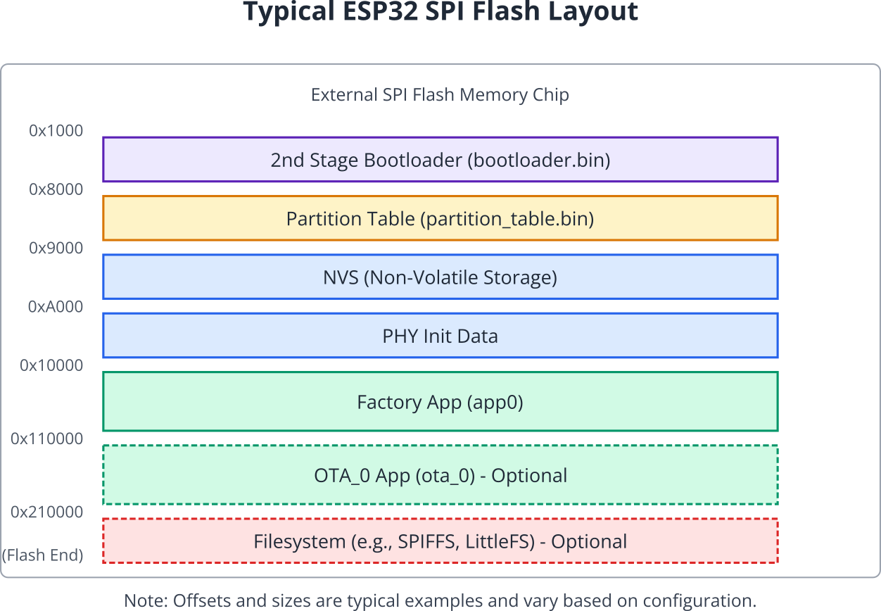
Common partition types include:
app: Stores application firmware. There’s usually afactoryapp and potentiallyota_0,ota_1, etc., for OTA updates.data: Stores data, such as:nvs: Non-Volatile Storage for key-value pairs.phy: PHY calibration data.spiffs,littlefs,fat: Filesystem data.coredump: Core dump storage for debugging crashes.
bootloader: Although the 2nd stage bootloader resides at0x1000, this partition type isn’t typically listed in the main table itself as its location is fixed.
The 2nd Stage Bootloader reads this table (located at 0x8000 by default) to find the location and size of the application partition it needs to load. Partition tables are defined in simple CSV format within your ESP-IDF project (e.g., partitions.csv) and compiled into a binary format (partition_table.bin) during the build process.
5. Application Loading and Execution
Once the 2nd Stage Bootloader identifies a valid application partition (e.g., factory), it performs the following:
| Step | Action | Details |
|---|---|---|
| 1. Verification | Integrity & Authenticity Check | Checks the application’s integrity (e.g., SHA-256 hash). If Secure Boot is active, verifies its digital signature against trusted keys. |
| 2. Loading | Copy to RAM | Copies executable code segments (e.g., .iram0.text) and initialized data segments (e.g., .dram0.data) from the application binary in Flash to their designated RAM locations (IRAM, DRAM). |
| 3. Memory Mapping | XIP (Execute-In-Place) | Read-only data (.rodata) and some code sections are typically mapped directly from Flash and accessed via the CPU’s instruction/data cache (XIP), saving RAM. |
| 4. Jump | Transfer Control | Transfers CPU control (jumps) to the application’s designated entry point function (e.g., call_start_cpu0 on ESP32). |
6. Application Startup
The application code now takes over. The initial application startup code (part of ESP-IDF, before app_main) performs tasks like:
| Task Area | Specific Actions by ESP-IDF Startup Code |
|---|---|
| Hardware Initialization | Initializes remaining hardware peripherals not handled by the bootloader (e.g., specific timers, ADC, DAC, I2C, SPI buses if configured). Sets up system clock frequencies if not already optimal. |
| Memory Management | Sets up the heap memory manager, allowing dynamic memory allocation (malloc, free). Initializes .bss section (uninitialized global/static variables) to zero. |
| Operating System Setup | Initializes FreeRTOS services: scheduler, timers, queues, semaphores, mutexes. Configures system interrupt handlers. |
| C/C++ Runtime | Calls global C++ constructors. Initializes standard library components. |
| Task Creation & Scheduling | Creates the main application task (or tasks) which will eventually call your app_main() function. Starts the FreeRTOS scheduler, which begins multitasking. |
From this point, your custom application logic begins executing.
7. Secure Boot and Flash Encryption
ESP32 variants offer security features:
- Flash Encryption: Encrypts the contents of the SPI Flash (bootloader, partition table, applications, data). The keys are stored in eFuses and are hardware-protected. When enabled, the hardware transparently decrypts code/data as it’s read from Flash into the cache or RAM. This prevents unauthorized reading of the firmware from the Flash chip.
- Secure Boot: Ensures that only authentically signed firmware can be executed. The ROM Bootloader and 2nd Stage Bootloader verify the digital signature of the next stage bootloader and application, respectively, using keys stored in eFuses. This prevents running unauthorized or tampered firmware.
Warning: Enabling Flash Encryption and Secure Boot involves burning eFuses, which are one-time programmable (OTP) bits. Once burned, they cannot be easily reversed. Incorrect configuration can permanently brick the device or lock you out. Approach these features with extreme caution and thorough understanding, starting with development kits before production hardware.
%%{ init: { 'theme': 'base', 'themeVariables': { 'fontFamily': 'Open Sans' } } }%%
graph TD
    A["Start: Considering Security Features<br>(Secure Boot / Flash Encryption)"] --> B{"Understand eFuses are<br>One-Time Programmable (OTP)"};
    B --> C["Action: Thoroughly Read ESP-IDF<br>Security Documentation!"];
    C --> D{"Have you backed up<br>all generated keys securely?"};
    D -- No --> E["STOP! Backup keys first.<br>Losing keys can be catastrophic."];
    E --> D;
    D -- Yes --> F{"Tested entire process on a<br>non-production development kit?"};
    F -- No --> G["STOP! Test on dev kit first.<br>Avoid bricking production hardware."];
    G --> F;
    F -- Yes --> H["Proceed with Extreme Caution<br>on Production Hardware"];
    H --> I["Potential Outcome 1:<br>Security Features Enabled Successfully"];
    H --> J["Potential Outcome 2:<br>Misconfiguration / Key Loss<br>Device Potentially Bricked or Locked"];

    %% Styling
    classDef startNode fill:#EDE9FE,stroke:#5B21B6,stroke-width:2px,color:#5B21B6;
    classDef processNode fill:#DBEAFE,stroke:#2563EB,stroke-width:1px,color:#1E40AF;
    classDef decisionNode fill:#FEF3C7,stroke:#D97706,stroke-width:1px,color:#92400E;
    classDef warningNode fill:#FEE2E2,stroke:#DC2626,stroke-width:1px,color:#991B1B;
    classDef successNode fill:#D1FAE5,stroke:#059669,stroke-width:2px,color:#065F46;

    class A startNode;
    class B,D,F decisionNode;
    class C,H processNode;
    class E,G,J warningNode;
    class I successNode;
| Feature | Primary Goal (Protection Against) | Mechanism | Key Storage | Impact if Keys Lost |
|---|---|---|---|---|
| Secure Boot | Execution of unauthorized or tampered firmware. | Digital signature verification. The ROM Bootloader verifies the 2nd Stage Bootloader, which in turn verifies the application. Each stage checks the signature of the next. | Public key hash or symmetric key stored in eFuses. Private key kept secret by developer. | Device will only boot firmware signed with the (now lost) private key. May prevent future updates if the signing key is unrecoverable. |
| Flash Encryption | Unauthorized reading/cloning of firmware and data from the external SPI Flash chip. | Encrypts the contents of the SPI Flash (bootloader, partition table, app, data). Hardware decrypts transparently when code/data is read into cache/RAM. | Encryption keys stored in eFuses, protected by hardware. | Firmware on Flash is unreadable without the keys. If eFuse keys are corrupted or device is misconfigured, device may be bricked as it cannot decrypt its own firmware. |
| Both features involve burning eFuses (One-Time Programmable memory). Incorrect configuration can be irreversible. | ||||
Practical Examples
Example 1: Examining the Partition Table
You can easily view the partition table flashed onto your device using ESP-IDF tools.
- Prerequisites: Have an ESP-IDF project built and flashed to a device. Connect the device.
- Method 1: Using
idf.py- Open the ESP-IDF Terminal in VS Code.
- Navigate to your project directory.
- Run the command:
idf.py -p <YOUR_PORT> partition_table(Replace<YOUR_PORT>with your device’s serial port). - Observe: The tool will connect to the device, read the partition table from Flash offset
0x8000, and print it in a readable format, showing partition names, types, subtypes, offsets, and sizes.
- Method 2: Using
parttool.pyparttool.pyoffers more specific partition operations.- Run the command to list partitions:
parttool.py -p <YOUR_PORT> read_partitions --offset 0x8000 # Default offset - To get info about a specific partition (e.g., “nvs”):
parttool.py -p <YOUR_PORT> get_partition_info --partition-name nvs - Observe: Similar output to
idf.py partition_table, butparttool.pycan also be used to read/write specific partitions (use with caution!).
Example 2: Entering Download Mode (Strapping Pins)
This example describes the physical procedure to force the ESP32 into Download Mode, allowing tools like esptool.py or idf.py flash to write to the Flash.
- Identify Strapping Pins: Consult the datasheet for your specific ESP32 variant and your development board’s schematic to identify the primary boot mode pin (usually GPIO0) and the enable/reset pin (EN or RST).
- Procedure (Typical for many ESP32 boards):
- Connect the ESP32 board to your computer via USB.
- Press and hold down the “BOOT” or “FLASH” button on your board (this usually pulls GPIO0 LOW).
- While holding the BOOT button, press and release the “EN” or “RST” button (this resets the chip).
- Release the “BOOT” button.
- Verification: The ESP32 should now be in Download Mode. You can verify this by running a command like:
esptool.py -p <YOUR_PORT> read_macoridf.py -p <YOUR_PORT> monitorIf successful,esptool.pywill connect and read the MAC address, or the monitor might show a “waiting for download” message from the ROM bootloader. If it fails or starts running the application, the strapping pins were likely not sampled correctly during reset. - Exiting Download Mode: Simply press and release the “EN” or “RST” button again (without holding BOOT) to reset the chip into normal Run Mode.
Tip: Most development boards have buttons wired correctly to simplify this process. The ESP-IDF flashing tools (
idf.py flash) often use DTR/RTS serial lines to automatically reset the board and manipulate the BOOT pin, putting it into download mode without manual button presses, but understanding the manual process is crucial for troubleshooting.
Variant Notes
While the overall boot process concept is similar, there are notable differences across ESP32 variants:
| Feature | ESP32 (Classic) | ESP32-S2 | ESP32-S3 | ESP32-C3 (RISC-V) | ESP32-C6 (RISC-V) | ESP32-H2 (RISC-V) |
|---|---|---|---|---|---|---|
| 1st Stage Loader | ROM | ROM | ROM | ROM | ROM | ROM |
| Strapping Pins (Key Boot Mode) | GPIO0, GPIO2, MTDI(12), GPIO5 | GPIO0, GPIO45, GPIO46 | GPIO0, GPIO46 | GPIO9, GPIO8 | GPIO9, GPIO8 | GPIO9, GPIO8 |
| Download Interface(s) | UART0 | UART0 / USB Serial/JTAG | UART0 / USB Serial/JTAG | UART0 / USB Serial/JTAG | UART0 / USB Serial/JTAG | UART0 |
| Secure Boot Version(s) | v1 | v1 / v2 (later chips) | v2 | v2 | v2 | v2 |
| Flash Encryption | Yes (AES-256 XTS) | Yes (AES-256 XTS) | Yes (AES-256 XTS) | Yes (AES-128 XTS) | Yes (AES-128 XTS) | Yes (AES-128 XTS) |
| eFuse Bits (Approx.) | 1024 | 1024+ | 1024+ | 768 | 768 | 768 |
| Default 2nd Loader Offset | 0x1000 | 0x1000 | 0x0 (Configurable) | 0x0 (Configurable) | 0x0 (Configurable) | 0x0 (Configurable) |
- Strapping Pins: The specific GPIOs used for strapping and their interpretation can differ significantly. Always check the datasheet for your specific SoC.
- Download Interface: Newer chips (S2, S3, C3, C6) often allow firmware download via the built-in USB Serial/JTAG controller, not just UART0.
- Secure Boot: Secure Boot v2 (available on newer chips) offers improved security and flexibility over v1.
- Flash Encryption: Algorithm (AES-256 vs AES-128) and implementation details vary.
- 2nd Loader Offset: On newer chips (S3, C3, C6, H2), the 2nd stage bootloader can be placed at offset
0x0instead of0x1000, simplifying the memory map slightly. This is configurable inmenuconfig. - ROM Code: The exact capabilities and behavior of the immutable ROM code differ between chip families.
Common Mistakes & Troubleshooting Tips
| Issue Category | Common Mistake / Cause | Symptom(s) | Troubleshooting Steps / Solution |
|---|---|---|---|
| Device Won’t Flash / Enter Download Mode | Incorrect strapping pin manipulation (GPIO0); Faulty USB cable/port; Incorrect serial port; Missing drivers (CP210x, CH340, etc.). | esptool.py or idf.py flash reports “Failed to connect…”, “Timed out waiting for packet header”. | Verify manual boot sequence (Hold BOOT, press/release RST, release BOOT). Check serial port (idf.py -p <PORT> monitor). Try different USB cable/port. Install/update drivers. Check board power. |
| Boots but Crashes Immediately (Guru Meditation) | Corrupted application; Incorrect Flash settings in menuconfig (size, mode, speed); Stack overflow early in app_main; Hardware issue (bad RAM). | Continuous resets; “Guru Meditation Error” in monitor. | Analyze backtrace (idf.py monitor). Check menuconfig Flash settings. Flash a simple “hello_world” example. Full chip erase (idf.py erase_flash) then re-flash. Review early app init code. |
| Partition Table Errors | Flashing app with different partition table than on device; Incorrect partitions.csv edits (overlaps, wrong types); Corrupted table. | Bootloader: “No bootable partition found”. NVS init failed. Filesystem mount fails. | Re-flash entire project (idf.py flash). Verify table on device (idf.py partition_table) matches project’s partitions.csv. If corruption suspected, erase_flash and re-flash. |
| Secure Boot / Flash Encryption Issues | Enabling without full understanding; Lost keys; Mismatch eFuse/firmware config; Flashing unencrypted/unsigned firmware to secured device. | Device refuses to boot. esptool.py security errors. Device potentially bricked. | EXTREME CAUTION. Read ESP-IDF Security Guide. Backup keys. Test on dev boards first. Ensure firmware built with correct security settings. Recovery may be impossible if keys lost/eFuses wrong. |
| Wrong Bootloader Image | Flashing bootloader for different ESP32 variant (e.g., ESP32 bootloader on ESP32-S3); Incompatible settings (Flash voltage/speed). | No boot at all; No serial output. | Ensure IDF project target (idf.py set-target) is correct. Flash bootloader built with the same project as app and partition table. |
Exercises
- Exploring with
esptool.py:- Put your ESP32 board into Download Mode using the strapping pins/buttons.
- Open a standard terminal or command prompt (not necessarily the ESP-IDF one, as
esptool.pyis often installed system-wide with ESP-IDF). - Run the following
esptool.pycommands (replace<YOUR_PORT>):esptool.py -p <YOUR_PORT> read_mac(Reads the base MAC address)esptool.py -p <YOUR_PORT> flash_id(Reads Flash manufacturer and device ID)esptool.py -p <YOUR_PORT> chip_id(Reads the unique Chip ID)esptool.py -p <YOUR_PORT> read_flash_status --bytes 2(Reads Flash status register)
- Observe the output for each command. What information can you gather about your specific chip and Flash memory directly from the ROM bootloader? Reset the board to exit Download Mode afterwards.
- Custom Partition Table:
- In your ESP-IDF project directory, find the
partitions.csvfile (or create one if using a default). - Make a backup copy of the original file.
- Edit partitions.csv to add a new custom data partition. For example, add a line like:mydata, data, spiffs, , 1M,(Ensure the offset is left blank so the tool calculates it, and adjust the size 1M as needed, ensuring it doesn’t overlap with other partitions or exceed Flash capacity).
- Save the file.
- Run
idf.py build. Observe the build output – it should mention processing the partition table. - Flash the entire project:
idf.py -p <YOUR_PORT> flash(This will write the newpartition_table.bin). - Verify the new table:
idf.py -p <YOUR_PORT> partition_table. Check if yourmydatapartition is listed with the correct details. (You haven’t added code to use this partition yet, just defined it).
- In your ESP-IDF project directory, find the
Summary
- The ESP32 boot process starts with the 1st Stage ROM Bootloader executing after reset.
- Strapping pins determine the boot mode (Run or Download). Download mode allows flashing via UART/USB using tools like
esptool.py. - In Run mode, the ROM loader loads the 2nd Stage SPI Bootloader (
bootloader.bin) from Flash offset0x1000(or0x0on newer chips). - The 2nd Stage Bootloader reads the Partition Table (from Flash offset
0x8000by default) to understand the Flash layout. - The Partition Table defines regions for applications (
app), data (nvs,phy, filesystems), etc. - The 2nd Stage Bootloader verifies and loads the selected Application image into RAM (IRAM/DRAM) and jumps to its entry point.
- Application startup code initializes peripherals, heap, FreeRTOS, and finally calls
app_main(). - Secure Boot verifies firmware signatures, while Flash Encryption protects Flash contents from unauthorized access. Both rely on eFuses and require careful handling.
- Boot processes and specific features (strapping pins, security versions) vary across ESP32 variants. Always consult the datasheet and ESP-IDF documentation for your target.
- Common boot issues involve incorrect strapping, flashing errors, corrupted images/partitions, or early application crashes.
Further Reading
- ESP-IDF Programming Guide: Bootloader: https://docs.espressif.com/projects/esp-idf/en/v5.4/esp32/api-guides/bootloader.html (Select your target chip in the documentation)
- ESP-IDF Programming Guide: Partition Tables: https://docs.espressif.com/projects/esp-idf/en/v5.4/esp32/api-guides/partition-tables.html
- Esptool.py Documentation: https://github.com/espressif/esptool/
- ESP-IDF Programming Guide: Secure Boot V2: https://docs.espressif.com/projects/esp-idf/en/v5.4/esp32/security/secure-boot-v2.html
- ESP-IDF Programming Guide: Flash Encryption: https://docs.espressif.com/projects/esp-idf/en/v5.4/esp32/security/flash-encryption.html
- ESP32 Series Datasheets: (Available on the Espressif website) – Contain definitive information on strapping pins and hardware specifics.
