
Chapter 212: 1-Wire Protocol Implementation
Chapter Objectives
By the end of this chapter, you will be able to:
- Understand the principles of the 1-Wire communication protocol.
- Describe the master/slave architecture and the role of timing in 1-Wire.
- Explain how devices are uniquely identified and addressed on a 1-Wire bus.
- Use the ESP32‘s RMT peripheral to implement a robust 1-Wire driver.
- Write ESP-IDF C code to discover and read data from a DS18B20 temperature sensor.
- Troubleshoot common hardware and software issues in 1-Wire networks.
Introduction
In the world of embedded systems, minimizing pin count is often a crucial design constraint. Imagine needing to connect dozens of sensors to a single microcontroller. If each sensor required two or three wires, you would quickly run out of GPIO pins. The 1-Wire protocol, developed by Dallas Semiconductor (now part of Maxim Integrated), elegantly solves this problem. As its name implies, it allows a master device to communicate with one or many slave devices over a single data line.
Beyond saving pins, 1-Wire also incorporates a unique feature called “parasite power,” where the slave devices can draw their operating power directly from the data line, eliminating the need for a separate power supply wire. Each device also comes with a globally unique, factory-programmed 64-bit address, allowing for simple discovery and multi-device networks.
In this chapter, we will explore the theory behind 1-Wire’s timing-critical communication. We will then implement a reliable driver using one of the ESP32’s most suitable peripherals for the job: the RMT (Remote Control) module, which is designed for generating and receiving precisely timed digital signals.
Theory
1. 1-Wire Bus Architecture
The 1-Wire bus has a simple master-slave architecture.
- Master: A single master device (our ESP32) controls the bus and initiates all communication.
- Slaves: One or more slave devices (e.g., sensors, EEPROMs) are connected to the same line and respond to commands from the master.
The bus itself consists of a single data line, labeled DQ. This line is connected to a GPIO pin on the master and to the DQ pin on all slave devices. A crucial component is an external pull-up resistor (typically 4.7 kΩ) that connects the DQ line to the VDD supply voltage.

When no device is transmitting, the pull-up resistor holds the line in its default high state. Both the master and slaves communicate by pulling the line low for specific durations.
2. Parasite Power
1-Wire devices can be powered in two ways:
- Normal Power: The slave device has a dedicated VDD pin connected to a power source.
- Parasite Power: The slave device derives its power from the DQ line. It has an internal capacitor that charges when the DQ line is high. The master must ensure the line is high for sufficient time to power the slaves, especially during power-intensive operations like a temperature conversion. For this reason, parasite power can sometimes be less reliable on long bus wires or with many devices.
3. The 1-Wire Protocol: A Game of Timings
Communication on the 1-Wire bus is not defined by voltage levels like UART or I2C, but by the precise duration of low pulses. The master always initiates communication. There are four fundamental operations:
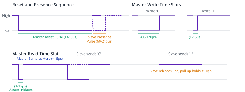
- Reset Pulse and Presence Pulse: The master begins all transactions by issuing a long Reset Pulse (pulling the line low for at least 480 µs). All connected slave devices recognize this and respond simultaneously with a Presence Pulse (pulling the line low for 60-240 µs). This allows the master to detect if any devices are present on the bus.
- Writing a ‘1’ Bit (Write-1 Slot): The master pulls the line low for a very short duration (1-15 µs) and then releases it.
- Writing a ‘0’ Bit (Write-0 Slot): The master pulls the line low for a longer duration (60-120 µs) and then releases it.
- Reading a Bit (Read Slot): The master pulls the line low for a short duration (1-15 µs) to start the time slot. It then releases the line. If the slave wants to send a ‘1’, it lets the line float high. If it wants to send a ‘0’, it continues to hold the line low for the duration of the time slot. The master samples the line’s state about 15 µs after it initiated the pulse to read the bit.
Analogy: Think of the 1-Wire protocol like communicating with a bell. A short ring (pulling low briefly) might mean “yes” (Write 1), while a long ring (pulling low for longer) might mean “no” (Write 0). The timing is everything.
4. Device Addressing: The 64-bit ROM Code
Every 1-Wire device has a unique, unchangeable 64-bit ID laser-etched into it at the factory. This ID is called the ROM code and consists of:
| Component | Bits | Byte(s) | Description | Example (for DS18B20) |
|---|---|---|---|---|
| 8-bit CRC Check | 63-56 | 1 Byte (MSB) | Cyclic Redundancy Check of the first 7 bytes. Ensures data integrity. | 0xA2 |
| 48-bit Serial Number | 55-8 | 6 Bytes | A unique serial number assigned at the factory. | 0x0167D3D0A2 |
| 8-bit Family Code | 7-0 | 1 Byte (LSB) | Identifies the type of 1-Wire device. | 0x28 |
The master can use this ROM code to address a specific device on a bus with multiple slaves.
5. Basic Transaction Flow
A typical interaction with a 1-Wire device follows these steps:
- Initialization: The master sends a Reset pulse and waits for a Presence pulse.
- ROM Command: The master issues a ROM command. The most common are:
SKIP ROM (0xCC): Address all devices on the bus simultaneously. Useful when only one slave is present.MATCH ROM (0x55): Followed by a 64-bit ROM code. Only the device with the matching ID will respond to subsequent commands.SEARCH ROM (0xF0): An iterative command used by the master to discover the ROM codes of all devices on the bus.
- Function Command: After addressing a device, the master sends a function command specific to that device’s capabilities (e.g., “start temperature conversion”).
- Data Transfer: The master either sends or reads data related to the function command.
graph TD
    A[Start] --> B{Reset &<br>Detect Presence};
    B -- Device(s) Present --> C{Issue ROM Command};
    B -- No Device Present --> G((End/Error));

    subgraph "ROM Command Selection"
        C --> D1["SKIP ROM<br>(0xCC)<br>Address All"];
        C --> D2["MATCH ROM<br>(0x55)<br>Address One"];
        C --> D3["SEARCH ROM<br>(0xF0)<br>Discover All"];
    end

    D1 --> E{"Issue Function Command<br>e.g., Convert Temp (0x44)"};
    D2 --> E;
    D3 --> E;

    E --> F{"Data Transfer<br>(Write or Read Data)<br>e.g., Read Scratchpad (0xBE)"};
    F --> G((End));

    classDef start_end fill:#D1FAE5,stroke:#059669,stroke-width:2px,color:#065F46;
    classDef process fill:#DBEAFE,stroke:#2563EB,stroke-width:1px,color:#1E40AF;
    classDef decision fill:#FEF3C7,stroke:#D97706,stroke-width:1px,color:#92400E;
    classDef io fill:#FEE2E2,stroke:#DC2626,stroke-width:1px,color:#991B1B;

    class A,G start_end;
    class C,E,F process;
    class B decision;
    class D1,D2,D3 io;
Practical Examples
The best way to implement the precise timing of 1-Wire on an ESP32 is with the RMT (Remote Control) peripheral. Bit-banging the protocol with ets_delay_us is possible but is blocking and can be made inaccurate by RTOS context switching. The RMT peripheral can be programmed to generate and read pulse trains with microsecond accuracy in the background, making it perfect for 1-Wire.
This example will show how to use RMT to find a DS18B20 sensor and read its temperature.
Prerequisites
- Hardware:
- An ESP32 development board.
- A DS18B20 temperature sensor.
- A 4.7 kΩ resistor.
- A breadboard and jumper wires.
- Software:
- VS Code with the ESP-IDF v5.x extension.
- A new ESP-IDF project.
Step 1: Wiring the Circuit
- Connect ESP32
GNDto the DS18B20GNDpin. - Connect ESP32
3.3Vto the DS18B20VDDpin. - Connect ESP32 GPIO 18 to the DS18B20
DQpin. - Place the 4.7 kΩ pull-up resistor between the
DQline and3.3V.
Tip: The GPIO pin used (18) is arbitrary. You can use almost any other GPIO pin, just be sure to update the
#definein the code.
Step 2: Writing the Code
We will write the code in a single file for simplicity, but for a real project, this logic should be moved into a dedicated onewire component. We’ll be using the newer RMT driver API available in ESP-IDF v5.0 and later.
| Byte | Content | Description |
|---|---|---|
| 0 | Temperature LSB | Least Significant Byte of the 12-bit temperature reading. |
| 1 | Temperature MSB | Most Significant Byte of the 12-bit temperature reading. |
| 2 | TH Register | User-programmable high temperature alarm trigger. |
| 3 | TL Register | User-programmable low temperature alarm trigger. |
| 4 | Configuration Register | Defines temperature conversion resolution (9, 10, 11, or 12 bits). |
| 5-7 | Reserved | Reserved for future use. Reads as 0xFF. |
| 8 | CRC | CRC-8 checksum of bytes 0 through 7. |
/* main/onewire_ds18b20_example.c */
#include <stdio.h>
#include "freertos/FreeRTOS.h"
#include "freertos/task.h"
#include "esp_log.h"
#include "driver/rmt_tx.h"
#include "driver/rmt_rx.h"
#include "driver/gpio.h"
static const char *TAG = "ONEWIRE_EXAMPLE";
#define ONEWIRE_GPIO 18
#define RMT_RESOLUTION_HZ 1000000 // 1MHz resolution, 1 tick = 1us
// RMT and 1-Wire timing configurations
#define ONEWIRE_RESET_PULSE_DURATION_US 480
#define ONEWIRE_PRESENCE_PULSE_MIN_US 60
#define ONEWIRE_PRESENCE_PULSE_MAX_US 240
#define ONEWIRE_WRITE_0_PULSE_DURATION_US 60
#define ONEWIRE_WRITE_1_PULSE_DURATION_US 6
#define ONEWIRE_READ_PULSE_DURATION_US 6
#define ONEWIRE_TIMESLOT_DURATION_US 70 // Give enough time for the slave to respond
// DS18B20 ROM Commands
#define DS18B20_CMD_SKIP_ROM 0xCC
#define DS18B20_CMD_READ_ROM 0x33
#define DS18B20_CMD_MATCH_ROM 0x55
#define DS18B20_CMD_SEARCH_ROM 0xF0
// DS18B20 Function Commands
#define DS18B20_CMD_CONVERT_T 0x44
#define DS18B20_CMD_READ_SCRATCHPAD 0xBE
static rmt_channel_handle_t tx_channel = NULL;
static rmt_channel_handle_t rx_channel = NULL;
static rmt_encoder_handle_t bytes_encoder = NULL;
static rmt_encoder_handle_t copy_encoder = NULL;
/**
* @brief Initialize RMT TX and RX channels for 1-Wire
*/
static void onewire_rmt_init(void) {
// RMT TX channel configuration
rmt_tx_channel_config_t tx_chan_config = {
.clk_src = RMT_CLK_SRC_DEFAULT,
.gpio_num = ONEWIRE_GPIO,
.mem_block_symbols = 64,
.resolution_hz = RMT_RESOLUTION_HZ,
.trans_queue_depth = 4,
};
ESP_ERROR_CHECK(rmt_new_tx_channel(&tx_chan_config, &tx_channel));
// RMT RX channel configuration
rmt_rx_channel_config_t rx_chan_config = {
.clk_src = RMT_CLK_SRC_DEFAULT,
.gpio_num = ONEWIRE_GPIO,
.mem_block_symbols = 64,
.resolution_hz = RMT_RESOLUTION_HZ,
};
ESP_ERROR_CHECK(rmt_new_rx_channel(&rx_chan_config, &rx_channel));
// Create RMT encoders
rmt_bytes_encoder_config_t bytes_encoder_config = {
.bit0 = {
.level0 = 1, .duration0 = ONEWIRE_WRITE_0_PULSE_DURATION_US,
.level1 = 0, .duration1 = ONEWIRE_TIMESLOT_DURATION_US - ONEWIRE_WRITE_0_PULSE_DURATION_US,
},
.bit1 = {
.level0 = 1, .duration0 = ONEWIRE_WRITE_1_PULSE_DURATION_US,
.level1 = 0, .duration1 = ONEWIRE_TIMESLOT_DURATION_US - ONEWIRE_WRITE_1_PULSE_DURATION_US,
},
.flags.msb_first = 0, // LSB first
};
ESP_ERROR_CHECK(rmt_new_bytes_encoder(&bytes_encoder_config, &bytes_encoder));
rmt_copy_encoder_config_t copy_encoder_config = {};
ESP_ERROR_CHECK(rmt_new_copy_encoder(©_encoder_config, ©_encoder));
// Enable channels
ESP_ERROR_CHECK(rmt_enable(tx_channel));
ESP_ERROR_CHECK(rmt_enable(rx_channel));
ESP_LOGI(TAG, "1-Wire RMT driver initialized");
}
/**
* @brief Send a 1-Wire reset pulse and check for presence pulse
* @return true if a device is present, false otherwise
*/
bool onewire_reset(void) {
// Reset pulse
rmt_symbol_word_t reset_pulse = {
.level0 = 1, .duration0 = ONEWIRE_RESET_PULSE_DURATION_US,
.level1 = 0, .duration1 = 0, // No second level
};
rmt_transmit_config_t tx_config = {.loop_count = 0};
ESP_ERROR_CHECK(rmt_transmit(tx_channel, copy_encoder, &reset_pulse, sizeof(reset_pulse), &tx_config));
ESP_ERROR_CHECK(rmt_tx_wait_all_done(tx_channel, -1));
// Presence pulse check
rmt_rx_done_event_data_t rx_data;
rmt_receive_config_t rx_config = {.signal_range_min_ns = 1000, .signal_range_max_ns = ONEWIRE_RESET_PULSE_DURATION_US * 1000};
ESP_ERROR_CHECK(rmt_receive(rx_channel, NULL, 0, &rx_config)); // Start receiving
if (xQueueReceive(rx_channel->rx_queue, &rx_data, pdMS_TO_TICKS(100)) == pdPASS) {
rmt_symbol_word_t *symbols = rx_data.received_symbols;
// Check if the received pulse duration is within the valid range
if(symbols[0].duration0 >= ONEWIRE_PRESENCE_PULSE_MIN_US && symbols[0].duration0 <= ONEWIRE_PRESENCE_PULSE_MAX_US) {
return true;
}
}
return false;
}
/**
* @brief Write a byte to the 1-Wire bus
*/
void onewire_write_byte(uint8_t data) {
rmt_transmit_config_t tx_config = {.loop_count = 0};
ESP_ERROR_CHECK(rmt_transmit(tx_channel, bytes_encoder, &data, sizeof(data), &tx_config));
ESP_ERROR_CHECK(rmt_tx_wait_all_done(tx_channel, -1));
}
/**
* @brief Read a byte from the 1-Wire bus
* @return The byte read
*/
uint8_t onewire_read_byte(void) {
uint8_t result = 0;
// For each bit, send a read pulse and then sample the line
for (int i = 0; i < 8; i++) {
// Send read pulse
rmt_symbol_word_t read_pulse = {
.level0 = 1, .duration0 = ONEWIRE_READ_PULSE_DURATION_US,
.level1 = 0, .duration1 = ONEWIRE_TIMESLOT_DURATION_US - ONEWIRE_READ_PULSE_DURATION_US,
};
rmt_transmit_config_t tx_config = {.loop_count = 0};
ESP_ERROR_CHECK(rmt_transmit(tx_channel, copy_encoder, &read_pulse, sizeof(read_pulse), &tx_config));
ESP_ERROR_CHECK(rmt_tx_wait_all_done(tx_channel, -1));
// Listen for slave response
rmt_rx_done_event_data_t rx_data;
rmt_receive_config_t rx_config = {.signal_range_min_ns = 1000, .signal_range_max_ns = ONEWIRE_TIMESLOT_DURATION_US * 1000};
ESP_ERROR_CHECK(rmt_receive(rx_channel, NULL, 0, &rx_config));
if (xQueueReceive(rx_channel->rx_queue, &rx_data, pdMS_TO_TICKS(20)) == pdPASS) {
// If the slave holds the line low for longer than our read pulse, it's a '0'
// Otherwise, the pull-up makes it a '1'
if (rx_data.received_symbols[0].duration0 > (ONEWIRE_READ_PULSE_DURATION_US + 5)) {
result |= (0 << i);
} else {
result |= (1 << i);
}
} else {
// Timeout implies a '1' as the line is pulled up
result |= (1 << i);
}
}
return result;
}
void app_main(void) {
onewire_rmt_init();
while (1) {
// 1. Send Reset Pulse and check for presence
if (!onewire_reset()) {
ESP_LOGE(TAG, "No 1-Wire devices found.");
vTaskDelay(pdMS_TO_TICKS(2000));
continue;
}
ESP_LOGI(TAG, "1-Wire device found, starting temperature conversion.");
// 2. Issue SKIP ROM command (since we have only one device)
onewire_write_byte(DS18B20_CMD_SKIP_ROM);
// 3. Issue Convert T command
onewire_write_byte(DS18B20_CMD_CONVERT_T);
// Wait for temperature conversion to complete.
// For 12-bit resolution, this can take up to 750ms.
vTaskDelay(pdMS_TO_TICKS(800));
// 4. Send Reset Pulse again
onewire_reset();
// 5. Issue SKIP ROM command again
onewire_write_byte(DS18B20_CMD_SKIP_ROM);
// 6. Issue Read Scratchpad command
onewire_write_byte(DS18B20_CMD_READ_SCRATCHPAD);
// 7. Read the 9 bytes of the scratchpad
uint8_t scratchpad[9];
for (int i = 0; i < 9; i++) {
scratchpad[i] = onewire_read_byte();
}
ESP_LOGI(TAG, "Scratchpad data: ");
ESP_LOG_BUFFER_HEX(TAG, scratchpad, 9);
// TODO: Add CRC check here (Exercise!)
// 8. Calculate temperature
int16_t temp_raw = (scratchpad[1] << 8) | scratchpad[0];
float temperature = temp_raw / 16.0;
ESP_LOGI(TAG, "Temperature: %.2f C", temperature);
vTaskDelay(pdMS_TO_TICKS(5000));
}
}
sequenceDiagram
    participant Master as ESP32 Master
    participant Slave as DS18B20 Slave

    Master->>Slave: 1. Reset Pulse
    Slave-->>Master: Presence Pulse

    Master->>Slave: 2. ROM Command: SKIP ROM (0xCC)
    Master->>Slave: 3. Function Command: Convert T (0x44)

    Note over Master,Slave: Master waits for conversion (e.g., 750ms)

    Master->>Slave: 4. Reset Pulse
    Slave-->>Master: Presence Pulse

    Master->>Slave: 5. ROM Command: SKIP ROM (0xCC)
    Master->>Slave: 6. Function Command: Read Scratchpad (0xBE)

    loop 9 times (for 9 bytes)
        Master->>Slave: 7. Read Slot
        Slave-->>Master: Return bit of scratchpad data
    end

    Note right of Master: Master assembles 9 bytes,<br>calculates CRC, and<br>computes temperature.
Step 3: Build, Flash, and Monitor
- Connect your ESP32 to your computer.
- Run
idf.py buildin the project terminal. - Run
idf.py -p [YOUR_PORT] flash. - Run
idf.py -p [YOUR_PORT] monitor.
If everything is connected correctly, you will see the ESP32 detect the sensor, command it to convert the temperature, read back the 9-byte scratchpad data, and finally print the calculated temperature in degrees Celsius every five seconds.
Variant Notes
- ESP32, ESP32-S2, ESP32-S3, ESP32-C3, ESP32-C6, ESP32-H2: All these variants are equipped with the RMT peripheral, and the ESP-IDF driver API used in this chapter is compatible across all of them. The number of RMT channels may vary (e.g., the original ESP32 has 8, while the ESP32-C3 has 4), but for a single 1-Wire bus, any variant is sufficient. The code provided should work on any of these chips without modification. The performance and reliability will be identical as the task is handled by dedicated hardware.
Common Mistakes & Troubleshooting Tips
| Issue | Symptom(s) | Solution |
|---|---|---|
| No Devices Found | onewire_reset() always returns false. |
1. Check Pull-Up Resistor: Ensure a 4.7kΩ resistor is between DQ and VDD. 2. Verify Wiring: Check GND, VDD, and DQ connections to the sensor. 3. Confirm GPIO Pin: Make sure ONEWIRE_GPIO in code matches the physical pin.
|
| Temperature is 85.0°C | The sensor always reports exactly 85 degrees Celsius. |
This is the power-on-reset value. You are reading the scratchpad before the temperature conversion is complete. Increase the delay after the DS18B20_CMD_CONVERT_T command (to at least 750ms for 12-bit resolution).
|
| Temperature is -0.06°C | The sensor always reports a value of -0.0625 or similar small negative number. |
This corresponds to a raw value of 0xFFFF. It often indicates that the sensor lost power during the conversion. Check VDD stability or switch from parasite power to normal power mode for testing.
|
| Incorrect CRC | The calculated CRC of the first 8 scratchpad bytes does not match byte 9. | This indicates a communication error. The bus might be noisy, the wires too long, or the pull-up resistor value incorrect for the bus length. Try shorter wires or a stronger pull-up (e.g., 2.2kΩ). |
Exercises
- CRC Check: The 9th byte of the DS18B20 scratchpad is a CRC of the first 8 bytes. Read the DS18B20 datasheet to understand the CRC-8 algorithm used. Implement a function to calculate the CRC of the received data and verify it against the received CRC. Log an error if they do not match.
- Multi-Device Discovery: The provided code uses
SKIP ROM, which only works well with one device. Modify the code to implement theSEARCH ROM (0xF0)command flow. Create a function that discovers all devices on the bus and prints their unique 64-bit ROM codes to the console. - Address a Specific Device: Using one of the ROM codes you discovered in Exercise 2, modify the main loop to use the
MATCH ROM (0x55)command followed by the 64-bit address to get a temperature reading from only that specific sensor. - Create a Reusable Component: Abstract the 1-Wire and DS18B20 logic into a proper ESP-IDF component named
onewire. Createonewire.hwith function prototypes andonewire.cwith the implementation. Theapp_mainfunction should then simply includeonewire.hand call high-level functions likeds18b20_get_temperature(rom_code).
Summary
- 1-Wire is a master-slave protocol that communicates over a single data line (DQ), requiring a pull-up resistor.
- Communication is timing-critical, with bit values defined by the duration of low pulses.
- Each device has a unique 64-bit ROM code, allowing multiple devices to coexist on the same bus.
- The ESP32’s RMT peripheral is ideal for implementing a reliable, non-blocking 1-Wire driver.
- A typical transaction involves a Reset/Presence pulse, a ROM command (like
SKIP ROMorMATCH ROM), and a device-specific Function command. - Common devices like the DS18B20 temperature sensor are easily controlled using this protocol.
Further Reading
- Analog Devices’ Book of iButton Standards: Provides the definitive guide to the 1-Wire protocol. https://www.analog.com/en/resources/technical-articles/book-of-ibuttonreg-standards.html
- DS18B20 Datasheet: Essential reading for understanding its function commands, scratchpad layout, and CRC calculation.
- ESP-IDF RMT Driver Documentation: For more advanced usage of the RMT peripheral. (https://docs.espressif.com/projects/esp-idf/en/v5.2.1/esp32/api-reference/peripherals/rmt.html)
