Interactive Logic Gate Simulator Lab

Logic Gate Simulator
Welcome! This simulator helps you understand how basic logic gates work. Logic gates are the fundamental building blocks of digital circuits. Toggle the inputs (0 or 1) for each gate and observe how the output changes based on the gate’s specific rule. The lines and gates will light up (turn yellow) when the signal is ‘1’ (true), and the output lamp will illuminate.
AND Gate
The AND gate outputs ‘1’ only if both Input A AND Input B are ‘1’. Otherwise, the output is ‘0’.
OR Gate
The OR gate outputs ‘1’ if either Input A OR Input B (or both) is ‘1’. It only outputs ‘0’ if both inputs are ‘0’.
NOT Gate (Inverter)
The NOT gate, also called an inverter, has only one input. It outputs the opposite of the input. If the input is ‘1’, the output is ‘0’, and vice-versa.
XOR Gate (Exclusive OR)
The XOR gate outputs ‘1’ only if the inputs are different (one is ‘1’ and the other is ‘0’). If both inputs are the same (both ‘0’ or both ‘1’), the output is ‘0’.
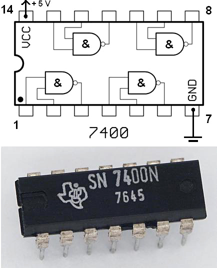
NAND Gate (NOT AND)
The NAND gate is the opposite of an AND gate. It outputs ‘0’ only if both inputs are ‘1’. Otherwise, the output is ‘1’. (Think: AND followed by NOT).
NOR Gate (NOT OR)
The NOR gate is the opposite of an OR gate. It outputs ‘1’ only if both inputs are ‘0’. Otherwise, the output is ‘0’. (Think: OR followed by NOT).
🔗 Recommended External Resources
- Logic.ly – Logic Circuit Simulator
An intuitive drag-and-drop logic simulator great for experimenting with basic and complex digital circuits. - CircuitVerse – Online Digital Logic Simulator
Open-source platform to build, simulate, and share digital logic circuits. Great for both students and educators. - DCACLab – Virtual Electronics Lab
Design and simulate circuits including DC and AC components in a real-time interactive environment. - PhET: Circuit Construction Kit – DC Virtual Lab
From the University of Colorado Boulder, this tool helps visualize and build basic DC circuits with intuitive controls. - TutorialsPoint – Digital Electronics Tutorial
Covers fundamental topics in digital electronics, from logic gates to sequential circuits.
