Kirchhoff’s Laws Virtual Lab
Explore Kirchhoff’s Voltage Law (KVL) and Kirchhoff’s Current Law (KCL) by adjusting circuit parameters and observing the results. These examples demonstrate the fundamental principles.
Kirchhoff’s Voltage Law (KVL)
KVL states that the algebraic sum of all voltages around any closed loop (or mesh) in a circuit must equal zero (ΣV = 0). This means the sum of voltage rises (like from a source) must equal the sum of voltage drops (like across resistors) in any loop. This series circuit demonstrates this: the source voltage (V) provides a rise, while the resistors (R1, R2, R3) cause drops (V1, V2, V3). Following the loop, we have V – V1 – V2 – V3 = 0.
Controls
KVL Circuit Diagram (Series)
Kirchhoff’s Current Law (KCL)
KCL (or Kirchhoff’s Junction Rule) states that the algebraic sum of currents entering any node (or junction) must equal the sum of currents leaving that node (ΣI_in = ΣI_out). This is based on the conservation of charge. In this parallel circuit, Node A is where the total current (It) enters and splits into I1, I2, and I3. Thus, It = I1 + I2 + I3 at Node A. At Node B, currents I1, I2, and I3 enter and recombine to form It leaving the node.
Controls
KCL Circuit Diagram (Parallel)
Combined KVL/KCL Simulation
This circuit requires both KVL and KCL for analysis. KCL is needed at Node A (where I_t splits into I2 and I3) and Node B (where I2 and I3 recombine into I_t). KVL is needed to analyze the voltage drops around the loops (e.g., V_source – V1 – V2 – V4 = 0).
Controls
Combined Circuit Diagram
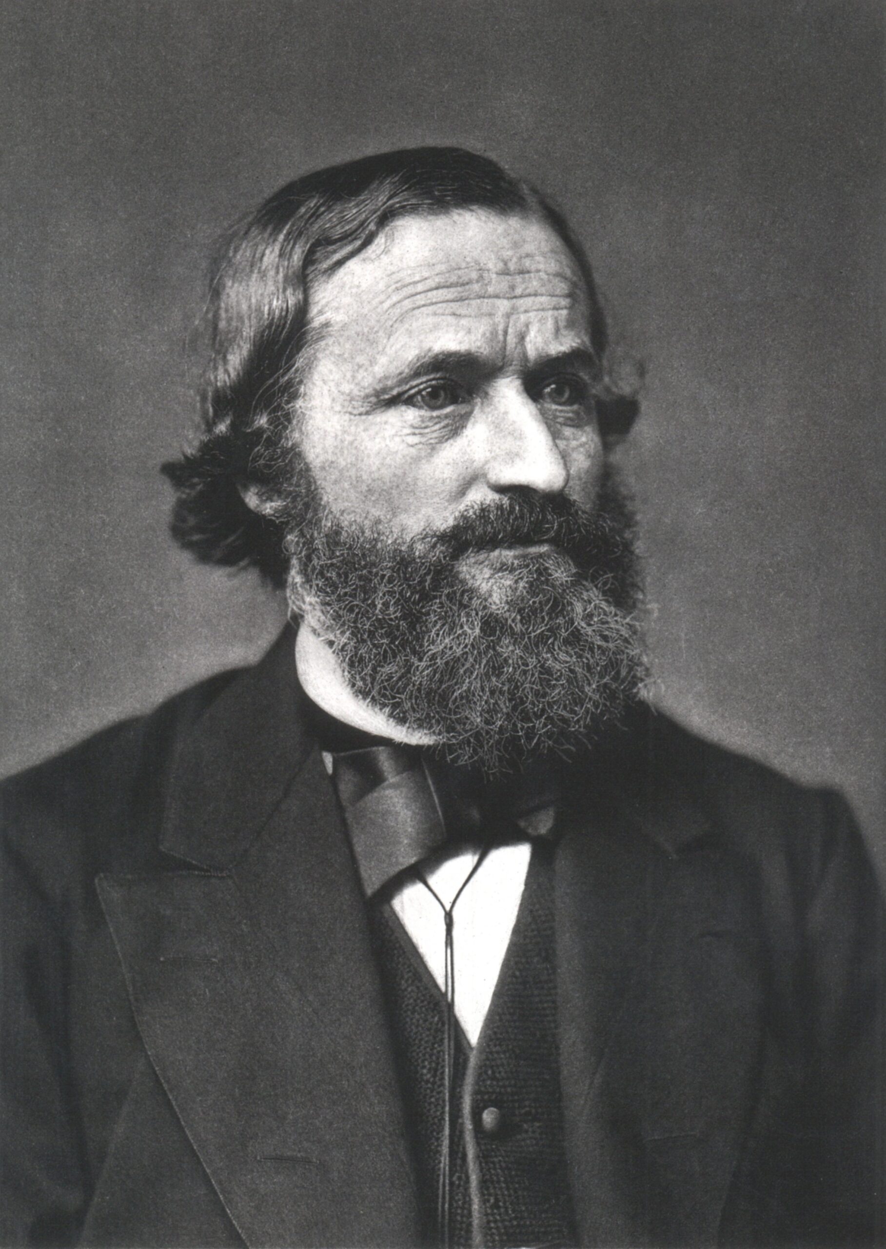
{/* Slightly taller canvas */}More for Gustav Kirchoff: Wikipedia 
More for Kirchoff’s Laws: Wikipedia
